18.08.2014
Use and operation
Important:
•The lifting jack may be set up only on horizontal-even,
capable of foundation.
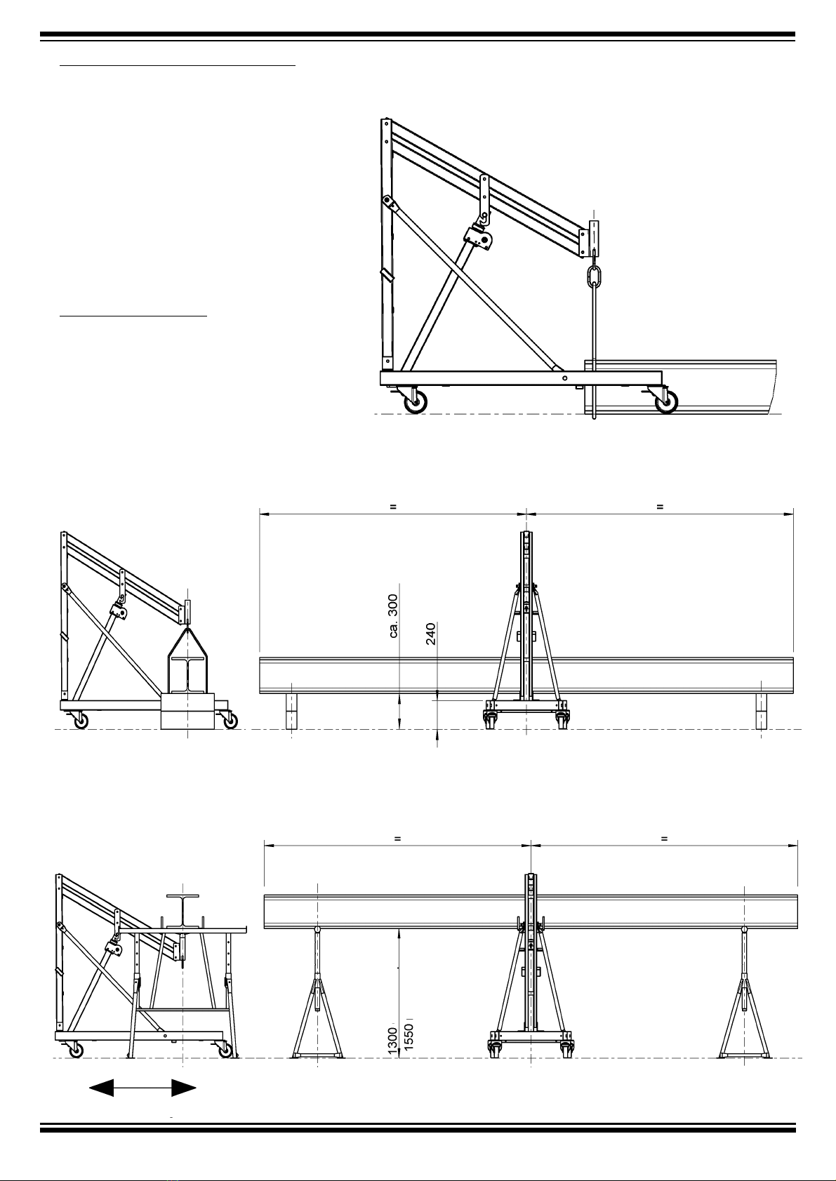
• The weight, e.g. a steel girder or a wood purlin, will be put
on the heading fork of the lifting jack or hooked into the
loop of the boom. The borings in the heading fork provide
the possibility of fixing the hung up load.
• The brakes of the swivel rollers must be fixed beforehand.
The swivel rollers should point to the outside once fixed,
to realise maximum contact width.
• If loads placed or suspended are to be moved, this must
be done in the deepest possible position of the boom.
When moving with lifted load there is a risk of turning
over!
• Moving with lifted load is only permissible in lifting jack
longitudinal direction! Risk of turning over!
• It is recommended to sweep off the surface on which the
lifting jack is moved under load. Even small stones hinder
the swivel rollers of the loaded device.
• Another recommendation is to additionally secure the
lifted load with scaffold jacks placed underneath during
movement.
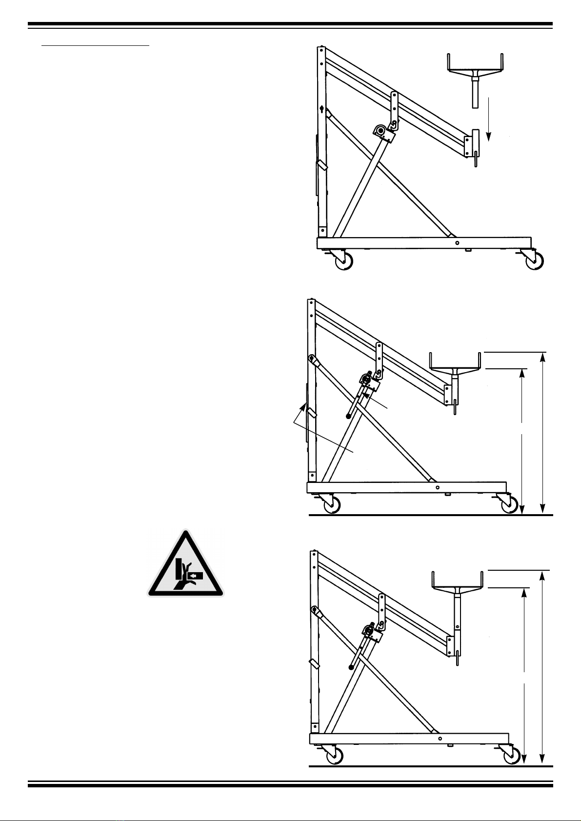
The crank for infinite lifting and lowering of the load can
be attached on both sides of the spindle gear.
Its length is adjustable, so that a large radius (lever arm)
for lifting, or a small radius (faster) for unloaded
movement can be set.
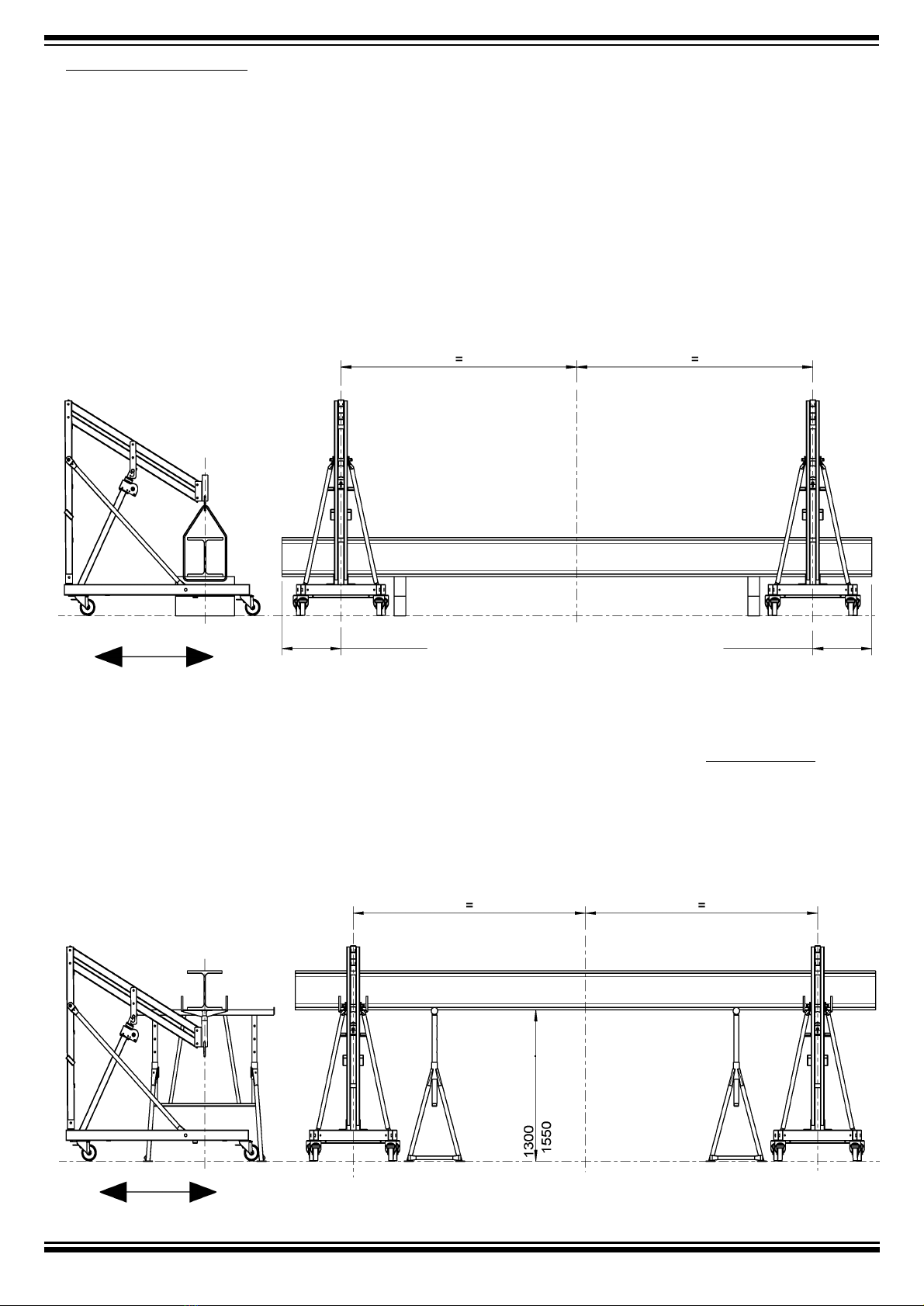
With the plug-on of the adapter, which is otherwise
between the two pipes of the stand, it is possible
to raise up the work height of the lifting jack
by 0.25 m to 3.00 m.
adapter
adapter
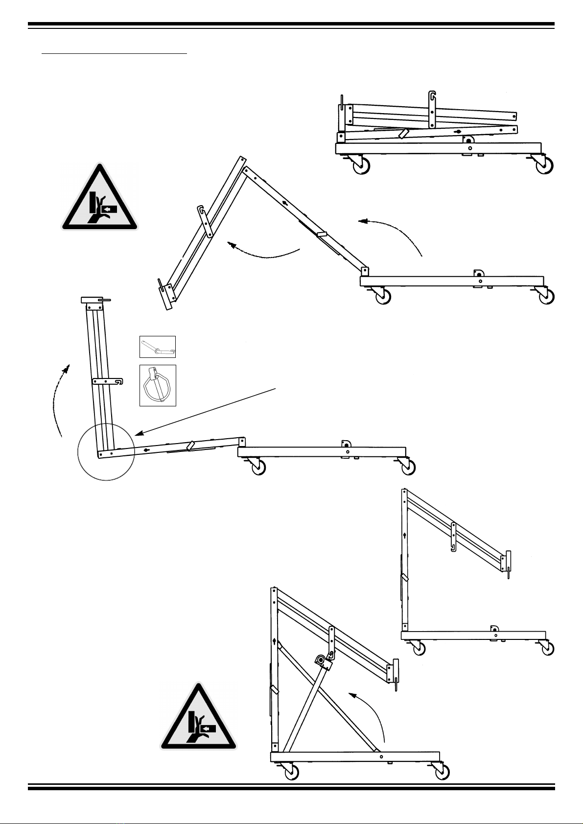
Caution, risk of crushing!
1.10 m
1.36 m
1.22 m
1.47 m
heading fork
load loop
crank