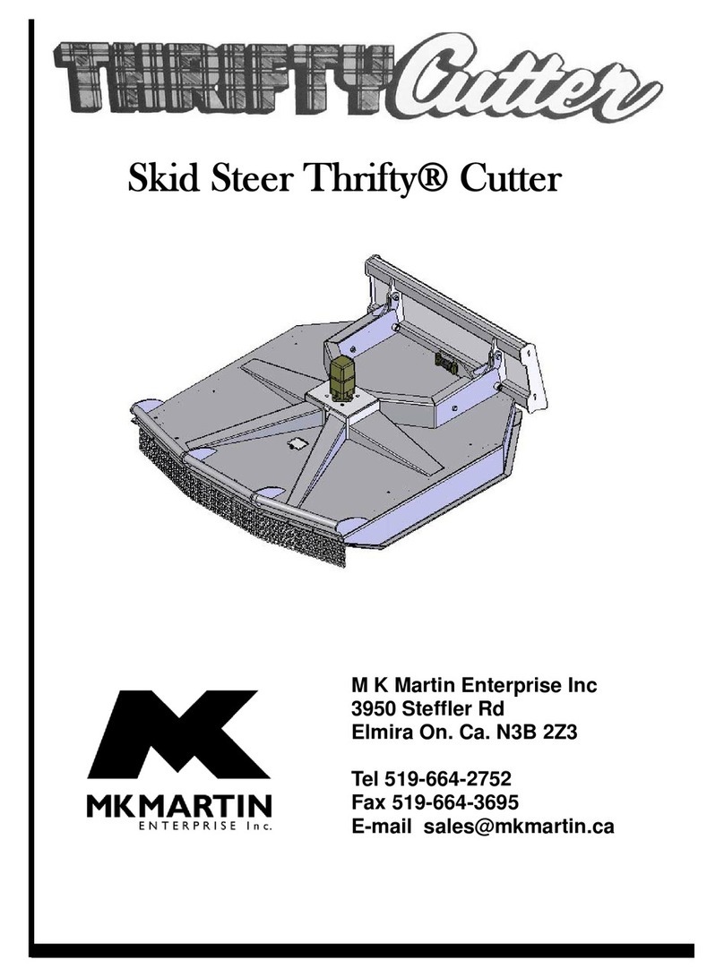
M K Martin Enterprise PULSAR 120 Product manual

M K Martin Enterprise Inc
3950 Steffler Rd Elmira On Ca N3B 2Z3
Tel: 519-664-2752
Toll Free 1-855-664-2752
Fax: 519-664-3695
E-mail: [email protected]
www.mkmartin.ca
120 Pulsar Cutter
Operator’s and Parts Manual


Table of Contents
1. Warranty
2. Registration
3. Safety
4. Decal Location
5. Setup Instructions
6. Cutter Operation
7. Main Cutter Parts
8. Tee Gearbox Parts
9. Angle Gearbox Parts
10.PTO Drive-line Installation
11. Cross Shaft (between gearbox)
12.Rear Drive Shaft with Slip-Clutch
13.Front PTO tractor
14.Bolt Torque Chart
15.Maintenance

Warranty
Eff ective on products retailed on or after November 1, 2017
Two Year Limited Consumer Warranty
Five Year Limited Consumer Warranty on Gearboxes
90 Day Limited Commercial Warranty including Gearboxes
Commercial includes rental and industrial applications.
Warranty begins at the time of customer delivery and is activated upon warranty registration receipt
at MK Martin Enterprise Inc.
Warranty coverage is null and void unless the Warranty Registration form has been completed
in full and is on le at
MK Martin Enterprise Inc.
Keep your registration copy in a safe place, it is required as proof of warranty activation.
This new and unused product is warranted by
MK Martin Enterprise Inc.
to be free from defects inmaterial and workmanship under
normal use and regular service as described in the owner’s manual, for a consumer period of 2 years and 5 years for gearboxes,
from the date of delivery, and commercial period of 90 days, including gearboxes, from the date of delivery. Warranty is limited to
the replacement of parts and / or repair of the product.
If issues develop within the warranty period with the product, contact the local dealer from which you purchased the unit. Only
MK
Martin
authorized dealers may make repairs to the product or a ect the replacement of defective parts, unless otherwise approved
by
MK Martin
. Repairs / replacement will be done at no charge within a reasonable time after the receipt of the product.
This warranty does not cover the following items:
1. Normal replacement of service items.
2. Normal maintenance or adjustments.
3. Machines or parts lost or damaged during shipment,
4. Accessory items / parts not supplied by
MK Martin
5. Damages resulting from:
misuse, negligence, accident, theft or re
use of improper or insuffi cient fuel, uids or lubricants
use of after market parts or accessories, unless approved by
MK Martin
modi cations, alteration, tampering or improper repair
any device or accessories installed by other than an authorized dealer.
6. Tires are covered by the manufacturer of the tire and the warranty period speci ed by that manufac-
turer. Please contact the tire manufacturer for warranty on these items.
MK Martin Enterprise Inc.
shall not, in any event, be liable for any losses, damages or costs; to include pro ts, travel, transportation,
pick up, delivery, towing cost, tow vehicle, loss of use, whether special, incidental, consequential or otherwise, in any way. Unit or
parts are returned at the customer’s expense.
Include a copy of your completed Warranty Registration form with any claim as proof of warranty activation.
There are no warranties, expressed or implied, other than those speci ed herein. No agent, employee or other person has any
authority to vary any of the foregoing provisions.
Warranty coverage is null and void unless the Warranty Registration form has been completed in full and is on le at MK Martin Enterprise Inc.
Warranty begins at the time of customer delivery and is activated upon Warranty Registration receipt at MK Martin Enterprise Inc.
3950 Steffl er Rd. Elmira Ontario, Canada N3B 2Z3 Email : [email protected] Fax : (519)-664-3695 Tel : (519)-664-2752
230817

M K Martin Enterprise Inc
3950 Steffl er Rd
Elmira ON CA N3B 2Z3
---------------------------------------------------------------------------------------------------------------------
Purchaser’s warranty protection is valid only when this completed form or a copy of this form
is on fi le at M K Martin Enterprise Inc. By fi lling out this form the purchaser has acknowledged
delivery of equipment and owner’s / operator’s manual and has accepted the condition of the
equipment.
Date of delivery to purchaser -------------------------------------------------------
Type of Equipment -------------------------------------------------------------------
Model # ------------------------------- Serial # -------------------------------------
Retailer’s Signature Indicates
• Equipment was properly assembled as directed by manufacturer
• Equipment was tested for functionality and operates properly
• Purchaser was instructed in safe and proper operating procedures
• Warranty was explained to purchaser
• Purchaser was given the operators manual
Retailer
Signature ----------------------------------------------------------------
Company ---------------------------------------------------------------
Address ---------------------------------------------------------------
-------------------------------------------------------------
Purchaser’s signature indicates
• Acceptance of equipment fully assembled
• Received operator’s manual
• Clearly understands conditions of warranty
• Received instructions of safe and proper operation of equipment
Purchaser
Signature -----------------------------------------------------------
Company ---------------------------------------------------------
Mailing address -------------------------------------------------
City ------------------------------------------ Prov/State -------- Postal Code/Zip ---------------
Available phone number -----------------------------------------
Warranty is valid only when it has been received by manufacturer at address above

-------------------------------------------------------------------------------------------------------------------------
Postage
Stamp
M K Martin Enterprise Inc
3950 Steffl er Rd
Elmira ON CA N3B 2Z3
Fold Here
Please Cut and Return to M K Martin Enterprise Inc
Fold And Tape here Do not tape all edges or use staples
Warranty Registration

Safety
Take Note! This safety symbol is found throughout this manual to call your attention to instruc-
tions involving yourself and others working around the machine.
• Failure to follow these instructions can result in injury or death
This symbol means
-- Attention!
-- Become Alert!
-- Your Safety is involved!
Signal words are used in this manual.
Caution: Indicates a potentially hazardous situation that may result in injury.
Warning: Indicates a hazardous situation that could result in serious injury or death.
Danger: Indicates a hazardous situation that needs to be avoided. It is you the operator that
needs to be aware of these dangers.
If you have any questions not answered in this manual please contact your dealer or
M K Martin Enterprise Inc Tel: 519-664-2752
3950 Steffl er Rd 1-855-664-2752
Elmira On Ca N3B 2Z3 Fax: 519-664-3695
www.mkmartin.ca

Safety - It’s in your interest!
Safety Guidelines.
Safety is one of our main concerns, however it is up to the operator to practice caution.
To avoid personal injury, study the following practice and insist that those working with you to
follow them.
The 120 Pulsar Rotary Cutter has guards on all the drive shafts for your protection, Do not
operate the cutter with the guards removed!
If they are damaged, repair or replace them!
Be careful with high pressure hydraulic lines! A high pressure uid spray can break the
skin and cause serious injury! Get immediate medical attention!
Rocks and other debris can be ejected at high speed and can injure or kill bystanders
in the vicinity. Keep all workers and spectators back 50 ft or more.
Replace any decals that may be missing or not be readable. Location of decals are indicated
elsewhere in this manual.
Do not use this machine while under the inuence of drugs or alcohol.
Review the safety instructions with all users annually.
This equipment should not be operated by children or those unfamiliar with the operation of the
Pulsar Cutter. Do not allow persons to operate this machine until they have read manual
and/or were instructed by a qualied person.
Do not paint over or remove or deface any safety signs or warning decals on the Pulsar Cutter.
Observe all safety signs and practice the instructions on them.

Decal Location
THIRD ANGLE PROJECTION
5
4
3
1
Folder
DWG. NO.
REV
Model
SCALE 1:4
SHEET 1 OF1
DATE DRAWN
MATERIAL
Pulsar Plus Logo
February-01-16 9:23:41 AM
DESCRIPTION
Pulsar Decal for Rotary Cutter & Finishing Mower
S:\Solidworks\Solidworks_Elo\Decal\
Weight(lbs.)
Width
Height
Length
sq. inch
"iERP_Stock_QPA@Default@Pulsar Plus Logo.SLDPRT"
Blank Size
Unit of Measure
ITEM ID.
decalPulsar
Config ID
Default
DIMENSIONS ARE IN INCHES
TOLERANCES NON SPECIFIED:
FRACTIONAL
1/64
BEND
1.0
TWO PLACE DECIMAL
0.01"
THREE PLACE DECIMAL
0.002"
Notes
DO NOT SCALE DRAWING
THIRD ANGLE PROJECTION
5
6
8
1
2
3
4
7
9
5
4
3
1
Folder
\\DC1\engineering\Solidworks\Solidworks_Elo\Cutter\Thrifty\120\120 Pulsar Cutter.SLDASM
DWG. NO.
REV
Model
SCALE 1:96
SHEET 2 OF2
DATE DRAWN
MATERIAL
120 Pulsar Cutter
December-03-13 8:47:01 AM
DESCRIPTION
120 Pulsar Cutter
S:\Solidworks\Solidworks_Elo\Cutter\Thrifty\120\
Weight(lbs.)
0
Width
Height
Length
0 0
1551.79
0
Blank Size
Unit of Measure
ITEM ID.
10265
Config ID
10265
DIMENSIONS ARE IN INCHES
TOLERANCES NON SPECIFIED:
FRACTIONAL
1/64
BEND
1.0
TWO PLACE DECIMAL
0.01"
THREE PLACE DECIMAL
0.002"
Notes
DO NOT SCALE DRAWING
#2 - Before any operation of main-
tenance a/o adjustment, stop, brake
the tractor on level ground, lower the
machine to the ground and read the in-
struction manual.
#6 - DANGER. Sharp objects could be
thrown. Keep safe distance from the
machine
#5 - DANGER of possible shearing
of limbs. Do not reach under mower
deck unless all moving parts of the
machine have reached a complete
standstill.
#8 - DANGER of possible shearing
of limbs. Keep a safe distance from
the machine while it is working.
#7 - DANGER of being caught by the
PTO shaft. Do not go near the rotating
members of the machine while in op-
eration.
#1 - Before operating machine,
carefully read the instruction manual
#4 - DANGER of being crushed.
Do not get between the tractor and the
machine.
#3 - MK Martin
Made in Canada
#9 - Pulsar
decal - x2

Setup Information
With the deck at on a rm surface and the cylinder retracted the hitch should be at draw-bar
height. The hitch control rods can be adjusted for some height variation,. You may need to ad-
just the tractor draw-bar height as well.
After nishing the adjustment, measure to ensure that pin to pin measurement is equal on both
control rods.
Control Rod
Control Rod Pins
Hitch Leveling Bars
Adjustment can be done
At both ens if necessary
To Adjust Control Rod
Loosen jam nut
Remove Control Rod Pin
Screw Yoke in or out on the Control Rod for proper ad-
justment.
Ensure that there is a minimum of 1” of thread inside the
yoke, and that nothing will bind or interfere as the cylin-
der goes through it’s full range.
Secure the jam-nuts.

PTO Cutting Informational Cont.
Equipment Raised and Tractor
turned sharp
is will be the collapsed length of
PTO drive sha
Fig 1
PTO Sha
Collapsed
PTO Sha
Extended
Fig 2
Equipment Lowered and tractor straight.
is will be the extended length of the
PTO drive sha.
Aer the sha has been modied and before installing it. Raise the equipment and turn the tractor sharp
and install the sha. If you can attach the PTO sha in this position you will minimize the chance of the
sha being too long and damaging the equipment.
Lower the equipment and turn the tractor straight (g 2), check the overlap on the PTO Sha. I should
have a minimum of 6 inches or 1500mm.

Operation
After the tractor is attached, the PTO and the hydraulic lines have been connected, raise and
lower the deck to ensure that the lifting linkage is working properly and the hydraulic lines are
not being caught or pinched..
Notice , the deck will stay parallel to the ground as cutting height is changed and the hitch yoke
also stays parallel.
At the location that you want to cut, lower the deck to your preferred cutting height.
With the tractor engine at a slow speed slowly engage the PTO and slowly bring the engine
speed to 540 PTO speed. If the cutter is turning slower, the cutting tips can not make a clean
cut. The cut will look ragged and uneven as it tends to tear the product o.
The eld or area should be cleared of any rocks, stones, branches lumber etc before starting to
cut. This will protect the cutter from getting damaged form debris that may have been hidden.
Do not use the cutter with any people within 100ft or 30M. Ejected debris can cause
severe injury to any bystanders.
During cutting, use a gear that will allow the PTO speed to stay at 540 RPM and the ground
travel to be slow enough to allow the cutting edges to work properly.
Machine Break-in
After using new machine 1/2 hour or cutting 2 aces, stop and do a break-in check.
1. Park on a clean rm place and place blocks or stands under the deck to prevent it from
lowering.
2. Check all bolts and nuts for there proper torque.
3. Check all cotter-pins, replace any broken or missing.
4. Check for ant oil leaks (oily areas around gearbox, hydraulic line and cylinder).
5. Check oil level in gearbox, top up if needed.
6. Grease PTO and Drive joints.
After 10-15 Hours, repeat steps 1-6 above.
After you have ensured that all the nuts and bolts are staying tight, regular maintenance can
be started as per service and maintenance page at back of manual.
Storing the Cutter
Store Pulsar Cutter in a clean dry location.
Clean all dirt and residue from deck.
After cleaning the underside of the deck, lightly coat with oil to prevent the bare metal parts
from rusting or paint the places where the paint is worn o.

Notes

Item # Part # Description Qty
1512-1201038 Front PTO 1
2512-1201039 PTO Intermediate Shaft Shield 1
3OL 3/16 Lynch Pin 1
4512-1201034 Rear Drive Shaft c/w Slip-Clutch 1
5OL mm8x1.25x16 Bolt 12
6512-1201042 PTO Shield 1
7OL 3/16 Lynch Pin 1
8512-1201041 PTO Shield Bracket 1
9512-120-1000 Main Deck 1
10 512-1201010 Gearbox Drive-Line 2
11 512-120F17A Angle Gearbox 2
12 512-1201013 Gearbox Drive-Line Shield 2
13 OL Bolt 3/8x1 c/w fw, lw, n 4
14 512-1201012 Tee Gearbox Shield Bracket 2
15 512-1201011 Tee Gearbox 1
16 512-1201016 Rear Rocking Beam 1
17 512-1201018 Wheel Hub Seal 2
18 512-1201019 Bearing Inner Cone 2
19 512-1201020 Bearing Inner Cup 2
20 512-1201017 Wheel Hub 2
21 ct555129 Pneumatic Wheel 2
22 512-1201026 Wheel Stud 10

Item # Part # Description Qty
23 512-1201021 Bearing Outer Cup 2
24 512-1201022 Bearing Outer Cone 2
25 512-1201023 Washer 2
26 OL 3/16x1 1/4 Cotter Pin 2
27 512-1201024 Wheel Nut 2
28 512-1201025 Dust Cap 2
29 512-1201009 Angle Gearbox Shield Bracket 2
30 OL 3/4 Nut c/w lw 8
31 OL 3/4 Nut c/w lw 6
32 OL 1/4x3/4 Flange Bolt c/w Flange Nut 2
33 DJ70111 Manual Tube 1
34 512-1201028 Rocker Beam Pivot Pin 2
35 OL Bolt 3/8x1 c/w lw 2
36 1501-0806 90° Adapter 2
37 OL 3x8 Hydraulic Cylinder 1
38 OL 1/4x168 Hydraulic Line c/w 3/8 M NPT 1
39 OL 1/4x156 Hydraulic Line c/w 3/8 M NPT 1
40 512-1201032 Cutting Tip 4
41 512-1201033 Blade Bolt c/w lw n 4
42 33623 Cutter Bar 2
43 33614 Tongue Pivot Bushing 2
44 OL Bolt 1x2 1/2 c/w ln 2
45 OL Bolt 1/2x1 1/2 c/w ln 2
46 OL 1/2 - 3/8 Reducer Bushing NPT 2
47 S71-4 Tractor Hydraulic Adapter 2
48 21915 Jack 1
49 512-1201002 Hitch Link 2
50 OL Bolt 1/2x2 c/w ln 1
51 512-1201008 Tongue 1
52 512-1201001 Hitch 1
53 33602 Hitch Pivot Pin 1
54 30260 Pin Cap (Washer) 2
55 OL Bolt 3/5 x c/w lw 2
56 512-1201005 Yoke Pin 4
57 512-1201004 Yoke 4
58 OL Jam Nut 5/8 NC 4
59 512-1201007 Tongue Control Rod 2
60 OL Bolt 1/2x2 1/2 c/w lw, n 4
61 512-1201035 Intermediate Shaft Bearing 2
62 512-1201036 Intermediate Shaft 1

Notes

TF 340 Tee Drive
Item
Description
Part No.
Req.
TF 340 J Gearbox
code no. 9.340.000.00
1
Input Seal
512-0.340.2000.00
1
2
Oil Seal 50 x 90 x 10
512-8.7.1.01107
1
3
Oil Plug 3/8
512-8.6.5.00006
1
4
Casing
512-0.340.0300.00
1
5
Cotter pin
512-8.4.7.01112
1
6
Castle nut
512-0.132.7107.00
1
7
Spacer
512-0.340.7400.00
1
8
Crown
512-U0.125.6060.00
1
9
Shim
512-0.712.7500.00
1
10
Screw M10 x 25
512-8.1.1.00061
8
11
Bearing 30310
512-8.0.9.00268
1
12
Cover
512-0.340.1300.00
1
13
Bearing 303210
512-8.0.9.00469
1
14
Output Shaft
512-0.340.3000.00
1
15
Oil Seal 45 x 85 x10
512-8.7.3.00331
2
16
Snap Ring 85dia.
512-8.5.2.01772
2
17
Shim
512-0.709.7500.00
2
18
Bearing 30209
512-8.0.9.00143
2
19
Pinion
512-U0.125.5060.00
1
20
Oil Plug 1/2
512-8.6.5.00203
1
21
Plate
512-0.124.7135.00
1
251
Oil filler level breather plug
512-0.340.7101.00
1

LF-140A.018
Item # Part # Description Qty
1 8.5.2.00131 Snap Ring 72 UNI7437 2
2 0.248.7500.00 Shim 60.3x71 2
3 8.0.1.00870 Bearing 6207 1
4 0.140.1300.00 Cover 1
5 8.1.1.00343 Bolt M8x14 4
6 8.6.7.00269 Oil Filler Plug 1/2” GAS 1
7 0.12407101.00 Plate 1
8 0.132.7106.00 Nut M30x1.5 1
9 8.4.7.0111 Cotter Pin B4x55 1

Item # Part # Description Qty
10 0116.5203.00 Crown Wheel Z19 M6,5 1
11 8.0.9.00026 Bearing 30207 1
12 8.7.3.00055 Oil Seal 35x72x10 1
13 0.140.2000.00 Sha 1”3/8Z6 1
14 0.132.5004.00 Pinion Z15 M6,5 1
15 0.712.7500.00 Shim 70.3 1
16 8.0.9.00469 Bearing 30210 2
17 8.7.1.01107 Dbl Lip Seal 50x90x10 1
18 0.139.7100.00 Protective Washer 1
19 0.140.3002.00 S h a 1
20 0.139.7101.00 Blank Washer 1
21 8.2.2.00555 Castle Nut M30x2 PR80 1
22 8.6.5.0006 Plug 3/8” GAS 2
23 0.140.0300.00 Casting 1
24 8.7.0.00744 Cap 72x10 1
A.139.000 1
251 0.1397000.00 Bush 1
252 8.4.7.00146 Cotter Pin B6x60 1

PTO Drive-line Dimension
The PTO Drive-line as supplied with the machine will need to be checked for the proper
length before being put into service.
To accommodate the various hitch and tractor con gurations the supplied shaft may be too
long, or in some case too short. To determine shaft length, nd the collapsed length, raise or low-
er the equipment until the PTO out of the tractor is horizontal with the input shaft on the machine.
Measure lock-pin groove to lock-pin groove or bolt hole on the equipment. If this is on trailed
equipment then turn tractor as sharp as possible.
Measure collapsed PTO shaft from lock-pin to lock-pin or bolt hole and compare it with the
measurement on the tractor. The di erence of these measurements needs to be cut from Both
Halves of the PTO shaft plus 1/2”.
Working Length overlap is 1/2 of above collapsed length
Minimum Overlap in Transport Position 1/3 of collapsed length
Following these guidelines will reduce the chances of damage to the equipment.
• Use a sharp hacksaw to cut the PTO tube
• Use a ne le to remove any sharp edges and burrs from sawing
• Clean o all dirt and lings from tube , carefully test for smooth t.
• Apply a light coat of grease to the outside of the small tube
• Reinstall the shields
• Install on equipment and recheck
These procedures need to be done before rst putting into operation and when attaching
to a diff erent tractor
Min 6 in
1500 mm
1/2 CL
1/3 CL
Collapsed Length (CL)
Table of contents
Other M K Martin Enterprise Farm Equipment manuals
Popular Farm Equipment manuals by other brands

Schaffert
Schaffert G2 Mounting instructions

Arrowquip
Arrowquip PORTABLE Q-CATCH 74 Series product manual

KUHN
KUHN HR4004D Operator's manual

Landoll
Landoll Weatherproofer III 2310 Series Operator's manual

LOFTNESS
LOFTNESS 61G4 Series Owner's manual and parts book

LEMKEN
LEMKEN TAURI 12 operating instructions