M Solutions MS104BAVOIP User manual

User Guide
MS-TestPro
HDBaseT™, HDMI, DCR and AVoIP Test Device
Revision: 1.2 - Feb 2022

02
support@m4sol.com |www.m4sol.com
MS-TestPro USER GUIDE
Introduction & Why the MS-TestPro 03
Hardware 04 - 05
Optional Hardware 06 - 07
HDBaseT Support & Cabling for HDBaseT 08
GUI - Home Page 09
GUI - Display Calibration 10
MS-TestPro Setup & Testing Types 11 - 12
WiFi / LAN Connectivity 13
HDBaseT Certification Test 14 - 15
MAX ERR and MSE ERR 16
HDBaseT Performance Testing 17 - 21
Log Analyzer 22 - 23
HDMI Pattern Generator 24
EDID Analyzer 25 - 26
Report Files 27 - 28
Cloud Connectivity 29
Device Power & PoH 29
Firmware / System Upgrade 29
Specifications 30
Contents
Notices
• This MSolutions product contains electrical components that may be damaged by electrical spikes, surges, electric
shock, lightning strikes, etc. Use of surge protection is highly recommended in order to protect and extend the life
of your equipment.
• The transmission distances of HDMI over CATx cables are measured using TE CONNECTIVITY 1427071-6 EIA/
TIA-568-B termination (T568B) of cables is recommended for optimal performance. To minimise interference of
unshielded twisted pairs in the CAT5e/6 cable, do not run the HDBaseT / CAT5e/6/6a cabling with or in close
parallel proximity to mains power cables.
• Do not substitute or use any other power supply other than the enclosed unit, or an MSolutions approved
replacement. Do not disassemble either the Tester, Transmitter, Receiver or optional Module units for any reason.
Doing so will void the manufacturer’s warranty.
• The terms HDMI and HDMI High-Definition Multimedia Interface, and the HDMI logo are trademarks or registered
trademarks of HDMI Licensing LLC in the United States and other countries.
• MSolutions reserves the right to change the specifications of this unit without prior notice. As a result of this,
physical representations or graphical elements contained within this user guide may not be accurate.

MS-TestPro USER GUIDE
03
support@m4sol.com |www.m4sol.com
Introduction
The MS-TestPro MS-104B is the only HDBaseT tester that is all-inclusive, 100% reliable,
portable and aordable, making this an indispensable tool for AV installers and integrators.
It provides AV professionals with all the information needed while in the field to enable
them to verify the integrity and stability of every system tested down to the last detail.
Moreover, the MS-TestPro generates a report including all the parameters necessary to
certify link quality and status for signals up to 4K Ultra High Definition. The report can then
be e-mailed, or transferred to a computer, tablet or smartphone for use by both installer and
end-user.
The device is supplied with HDBaseT Spec 1.0 Transmitter, Receiver, and PoH (Power over
HDBaseT) functionality, providing a highly-eicient testing platform for HDBaseT source
and sink nodes, powered devices, and CATx cabling intended for use in HDBaseT networks.
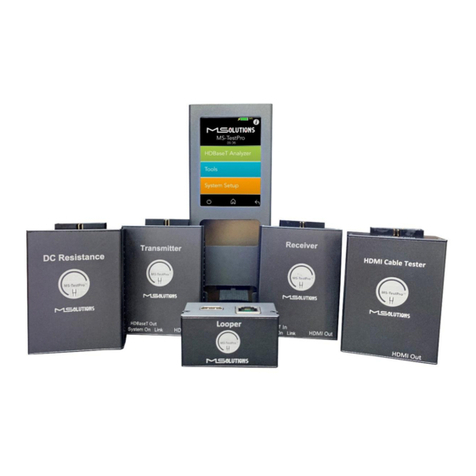
Optional modules include HDBaseT Spec 2.0, HCT (HDMI Cable Tester), DCR (DC
Resistance), and an optional license for AVoIP Network Analysis. Separate user guides for
these optional modules are available from the MSolutions website.
Why the MS-TestPro?
The wiring of an HDBaseT system has been completed, and the audio/visual devices have
been connected over the HDBaseT link. An image and sound may be present over the link,
but how well are these signal being sent and received?
A link test is essential in guaranteeing perfect and ongoing performance. A return visit to
site is not ideal for any intgerator or end user.
When the test device is connected and error levels are close or exceeding the orange dotted
line – even if the link is up and there is a picture on the display – the probability of a future
link failure is high. Any EMI (Electro Magnetic Interference) caused by switching on lights
or an air conditioning unit, can cause a transmission breakdown and a subsequent drop in
the video link.
With the MS-TestPro test device, faulty or inadequate cabling and systems can be identified
and remedied before leaving site, saving both time, money and reputation.

04
support@m4sol.com |www.m4sol.com
MS-TestPro USER GUIDE
Hardware
MS-TestPro
Side elevation
Top elevation Front elevation
Bottom elevation
Test pattern generator
HDMI output
Audio out
Power
USB
LAN / Ethernet
Power switch
Stylus
Data adapter
PoH Adaptor storage
Stylus

MS-TestPro USER GUIDE
05
support@m4sol.com |www.m4sol.com
HDBaseT Out HDMI In
HDBaseT In HDMI Out
Hardware
The MS-TestPro HDBaseT Test Device is supplied with HDBaseT Spec 1.0-standard TX and
RX modules. The HDBaseT Spec 2.0 Modules (TX and RX units) are available as an optional
add-on that can be used with the MS-TestPro to tesat for the additonal functionality
contained within the HDBaseT Spec 2.0 chipsets.
Spec 1.0 / 2.0 HDBaseT Transmitter Module
Spec 1.0 / 2.0 HDBaseT Receiver Module
HDMI input - connect to
HDMI output of MS-TestPro or
source device
Data adapter - connects
to inside of MS-TestPro if
being used locally, or to
PoH Adaptor if being used
remotely
HDBaseT output - connect to
CATx cable being tested
HDBaseT input - connect to
CATx cable being tested HDMI output - connect to
HDMI sink device to view live
image across HDBaseT link
Data adapter - connects
to inside of MS-TestPro if
being used locally, or to
PoH Adaptor if being used
remotely

06
support@m4sol.com |www.m4sol.com
MS-TestPro USER GUIDE
Optional Hardware
The HDMI Cable Tester (HCT) module allows installers and integrators to test the quality
and resolution support of HDMI cables before installation. The module identifies missing
and shorted wires in a HDMI cable that will render the cable incapable of 4K streaming.
HCT Module
The DC Resistance feature enables installers and integrators to check DC resistance
unbalance easily and reliably on CATx cables – both within and between twisted pairs
– ensuring system integrity in even the most advanced, high-powered PoH (Power over
HDBaseT) systems.
DCR Module
HDMI connection - connect
to one end of the HDMI cable
being tested
Data adapter - connects to
inside of MS-TestPro
Data adapter - connects to
inside of MS-TestPro
LAN / HDBaseT connection -
connect to CATx cable being
tested

MS-TestPro USER GUIDE
07
support@m4sol.com |www.m4sol.com
Optional Hardware
The Looper module is a remote-end module with RJ45 and HDMI ports that is used to
create the loop at the other end for HCT and DC Resistance testing. A Looper is supplied
with any HCT or DCR module purchase.
Looper
Looper
HDMI connection - connect
to opposite end of the HDMI
cable being tested as the HCT
Module
LAN / HDBaseT connection -
connect to CATx cable being
tested as the DCR Module

08
support@m4sol.com |www.m4sol.com
MS-TestPro USER GUIDE
HDBaseT Support
The MS-TestPro test device integrates a Valens VS100 HDBaseT Class A (Spec 1.0 Module
- included) or VS2310 HDBaseT class C (Spec 2.0 Module - sold separately) chipsets,
including transmit and receive IC’s. The class A chipset supports HDBaseT Specification
1.0, and is compatible with HDBaseT Specification 2.0, allowing it to work with HDBaseT
devices of the following classes as outlined in the HDBaseT Specification:
Class HDBaseT
Specification
Media Type Max Resolution Max Length Category
Class A 1.0 Copper 1080p
2160p 100m
70m Cat5e
Cat5e
Class B 1.0 Copper 1080p
2160p 70m
35m Cat6a
Cat5e
Class C 2.0 Copper 1080p
2160p
2160p
100m
90m
100m
Cat5e
Cat5e
Cat6a
Class D 2.0 Copper 1080p 30m Cat6a
Class E 2.0 Fibre 2160p Not support by MS-TestPro
Cabling for HDBaseT
It is important that the interconnecting CATx cable between HDBaseT products is
terminated using the correct RJ45 pin configuration. The link CATx cable should be a
‘straight’ (pin-to-pin) CAT cable and it is advised that this is wired to the T568B wiring
standard as this format is less prone to EMI (Electro-Magnetic Interference) using a
recommended of 24 AWG, solid core CATx cable.
When installing CATx cables it is advised that the best possible CAT cable quality possible
is used. HDMI distribution products will only work if used with CAT5e standard cable or
above. MSolutions recommends using a CAT6 (or higher) cable for installations, especially
when running over longer distances, in areas of high EMI, or for 4K signal distribution.
The HDMI cable infrastructure should be compliant to High-Speed standards, especially
where 4K is being distributed. It is important to understand that where excessive HDMI
cable lengths are used, this brings increased reduction in signal integrity over distance
compared to HDBaseT. It is therefore recommended to use short HDMI cables to ensure the
integrity of the signal over the link.
The use of HDBaseT Recommended CATx cabling is not a guarantee of performance, only
that the cable has been found to be worthy of recommendation by the HDBaseT Alliance.
The HDBaseT Alliance cannot guarantee the quality of the installation, or subsequent
termination of the cabling by the user.

MS-TestPro USER GUIDE
09
support@m4sol.com |www.m4sol.com
GUI - Home Page
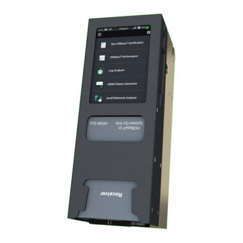
The home page of the MS-TestPro will be the first screen that appears on first powering on
the unit. See below overview of the home page:
Unit time: set up the
date / time from the
Settings menu Cloud connection:
Will be green
when connected
to the cloud
LAN connection: icon
will appear green when
connected to a LAN
Link: will show
green when there is
an active HDBaseT
connection
Battery indication:
shows charge left in
unit
Settings menu
Actions menu:
access EDID
Analyzer, Files,
Power, and Help
HDBaseT
Certification menu
HDBaseT
Performance menu
Log Analyzer menu
HDMI Pattern
Generator menu
AVoIP/Network
Analyzer menu
USB drive connected: icon
shown when a USB drive
is connected

10
support@m4sol.com |www.m4sol.com
MS-TestPro USER GUIDE
GUI - Display Calibration
Due to the size of the display included on the MS-TestPro there are certain menus and
options that require a precise press of the screen when usig the supplied stylus. It is
recommended to calibrate the display on furst use, then periodically depending on use.
To calibrate the display, click on the Settings menu in the top right of ther Home Page and
select Display Calibration:
Follow the instructions on screen, pressing the tip of the stylus on the red cross-hairs at the
given points on the screen. Once a calibration point has been confirmed, it will turn white,
and a new cross-hair will appear. A count-down timer will appear in the centre of the screen
between presses. Please complete the stylus press within the countdown period.
The MS-TestPro will need to be rebooted for the new calibration to complete. Reboot by
using the Power/Reboot sequence in the Actions Menu.
If, during normal use, it is apparent that button presses on the screen are not precise, please
re-run the display calibration.
IMPORTANT: It is recommended to always use the supplied stylus. Do not use a finger or
other ‘blunt’ instrument to calibrate the screen. Doing so may result in non-precise actions
during use. Likewise, do not use pens, or sharp objects to press on the screen, this may
inadvertantly damage the screen.

MS-TestPro USER GUIDE
11
support@m4sol.com |www.m4sol.com
MS-TestPro Test Setup
The Transmitter and Receiver modules of the MS-TestPro device are directly connected to
each other using a CATx cable of up to 100 meters (328 feet) in length as per the diagram
below. The Transmitter or Receiver module can be inserted into the base of the Tester
however, it is important to use the Transmiter unit at the end of the CATx cable where the
HDBaseT Matrix or Transmitter equipment is / will be located under normal operation. The
test can be carried out at either end of the CATx link.
Important: Always power down the MS-TestPro for cartridge (Transmitter / Receiver / HCT
/ DCR) replacement.
It is important to use the MS-TestPro with a live HDMI source device, or Test Pattern
Generator, to pass a HDMI signal over the link for the MS-TestPro to properly qualify the
link. The MS-TestPro can generate a range of HDMI signals (up to 4K 30Hz 4:4:4) using the
built-in Test Pattern Generator on the side of the unit. By default, the signal output from the
HDMI output of the tester is 4K 30Hz 4:4:4 (10G). By NOT connecting a HDMI signal to the
Transmitter unit, the live HDBaseT signal is just a ‘base-line’ signal which will not push the
bandwidth of the connection to that of a ‘live’ link.
If using a live source device, please limit the resolution output to 4K 30Hz 4:4:4, or, 4K 60Hz
4:2:0.
The HDBaseT Spec 1.0 and 2.0 modules do not require a signal that exceeds 10.2Gbps (4K
30Hz 4:4:4, or, 4K 60Hz 4:2:0) as this is the maximum HDMI data rate HDBaseT can accept
under normal conditions. HDBaseT equipment that can accept higher data-rate signals use
either conpression or conversion prior to the HDBaseT chipsets to limit the ceiling data rate
to that of the HDBaseT technology.

12
support@m4sol.com |www.m4sol.com
MS-TestPro USER GUIDE
MS-TestPro Test Setup
1. Remove Transmitter, Receiver and PoH Adaptor from the main tester body.
2. Insert either the Transmitter or Receiver module (as required) into the MS-TestPro main
unit in the lower slot. This will be known as the local module. Please note: only the lower
slot is used to connect modules to the MS-TestPro main unit. The upper slot is only used
for module storage during transport.
3. Use the guide rails to insert the local module into the tester pressing firmly to make a
solid connection between the data adaptors on both the local module and the tester
body.
4. Connect the CATx cable to the HDBaseT connection on the local module inserted into
the tester.
5. Run a short HDMI cable from the HDMI output located on the side of the MS-TestPro to
the HDMI input of the local module (assuming the local module is the Transmitter), or
from a HDMI source device, or 3rd party Test Pattern Generator to the HDMI input of the
Transmitter if the Transmitter is going to be used as the remote module.
6. Attach the PoH Adaptor to the remote (Transmitter or Receiver) module so that this will
function as the PoH powered device (PSE). Power over HDBaseT is sent from the local
module (PD) inserted into the tester, to the remote module over the CATx cable.
7. Connect the remote module to the HDBaseT port on other end of the CATx link.
8. Connect the Receiver module by HDMI to a display, or HDMI Analyser on the far end of
the CATx cable to see a live image being transferred over the HDBaseT link.
HDBaseT Testing Types
Depending on the reason for using the MS-TestPro, there are a few diering types of test
that can be undertaken.
1. HDBaseT Certification: unlike certification of an IP infrastructure, this test will verify
that a run of CATx cable is capable of carrying a HDBaseT signal. This test should be
used for new cabling runs, after installation / termination, to guarantee that 3rd party
HDBaseT manufacturers equipment can work over the cable infrastructure.
2. HDBaseT Performance: this is a “live view” of the HDBaseT signal passing across the
CATx link based on the image being supplied to the tester from its own HDMI pattern
generator, or a live HDMI source.
3. Log Analysis: this is used in instances where intermittent drop-out of signal is
experienced over a CATx cable run. This can be left “testing” the cable for up to 24 hours,
logging the signal quality at 1 second intervals.
The next few pages of this User Guide will outline the above tests in more detail.

MS-TestPro USER GUIDE
13
support@m4sol.com |www.m4sol.com
WiFi / LAN Connectivity
The MS-TestPro MS-104B features LAN connectivity allowing for a user to connect the
MS-TestPro to the network directly (via hardwired LAN), directly to the unit from a PC
(hardwired - DHCP), or using the built in AP to connect a mobile device, tablet or laptop
computer where no hard-wired LAN connection is available.
Connecting to the built-in AP:
Use this method where there is no
hard-wired connection to a LAN, or the
customers network.
• Click on the ‘Settings’ icon in the top
right of the home screen to access the
WiFi details
• The access point of the unit is noted in
the ‘AP Network’ field
• Search for this AP in the list of available
wireless networks
• Connect to the unit - no password
required
• Enter the default IP address of 192.168.11.1
into your browser to communicate with
the unit directly
Connecting the unit to a LAN:
Use this method when ther eis a hardwired LAN connection. Use the RJ45 connection on
the top of the MS-TestPro to connect to the network. The LAN Connection icon will appear
at the top of the display (see GUI Home Page for further details).
• Click on the ‘Settings’ icon
• Click on the ‘General’ menu at the top fothe list (as shown above)
• The IP address of the unit will be displayed under ‘Local IP’
• Insert this IP address into the browser of a smart phone, tablet or laptop that is
connected to the same LAN as the MS-TestPro

14
support@m4sol.com |www.m4sol.com
MS-TestPro USER GUIDE
HDBaseT Certification Test
The MSolutions MS-TestPro HDBaseT Certification test has been approved by the HDBaseT
Alliance as a recognised test for the defining of a CATx run as being suitable for the
transmission of a HDBaseT signal. This test would be used for new CATx cable runs, or for
existing runs to determine the suitability for stable HDBaseT transmission.
Select the first menu option on the main Home menu of the MS-TestPro to enter the
‘HDBaseT Certification’ page.
If using a CATx cable that has been included into the pre-defined Cable Profiles of the MS-
TestPro, use the Cable Profile selection towards the bototm of the screen to select the cable
type being used. Otherwise, leave this as ‘Standard’.
The MS-TestPro will quantify the HDMI signal being passed by the Pixel Clock notification.
Please note: the maximum pixel clock that HDBaseT can carry in Specifications 1.0 and 2.0
is 298MPixel.
Press ‘RUN’ to carry out the HDBaseT Certification test. The test will take approximately 10
seconds where the live HDMI signal (being inserted to the Transmitter module) will be sent
over the HDBaseT link for the test.
Please note: if a live HDMI signal is not inserted into the Transmitter module then the tester
can only test for basic DDC (Display Data Channel) information being sent and received.
This is not considered to be a true HDBaseT link test, as there is no physical video or audio
being transmitted.

MS-TestPro USER GUIDE
15
support@m4sol.com |www.m4sol.com
HDBaseT Certification Test
Once the test has finished, a PASS or FAIL result will be shown on the tester screen.
For more information on MAX ERR and MSE ERR values, see next page.
To save the test result into the memory of the MS-TestPro, click ‘SAVE’. Enter the details
into the 3 open text fields for: Customer, Job Site, Cable Type and Operator before hitting
‘Save’. The .pdf test report will be saved into the MS-TestPro internal memory that can
then be downloaded onto a USB drive. If the unit is connected to the Cloud, the report will
automatically be uploaded to the Cloud at this point.
The report can be downloded immediately by pressing ‘DOWNLOAD’ once saved. The
tester will revert to the HDBaseT Certifications download page.
See the ‘Report Files’ section later in this guide for instructions of how to download these
test reports.

16
support@m4sol.com |www.m4sol.com
MS-TestPro USER GUIDE
MAX ERR and MSE ERR
The MSolutions MS-TestPro measures both the quality of the signal being passed over the
cable, and the cables ability to pass the signal. These two pieces of performance data are
defined by MAX ERR and MSE ERR.
MAX ERR: the per-channel maximum recorded value of the residual error for PAM-8/-
16 modulation:
The Max Error measurement is the absolute value of the maximum distance between the
input signal on a given channel and the decision threshold in the HDBaseT modulation
detection scheme. This measurement behaves as a peak detector, so the value read is
always the maximum error witnessed on the channel. This refers directly to the HDBaseT
Receiver chips ability to un-modulate the signal and correct errors that are encountered.
MSE ERR: the per-channel mean square of the residual error for PAM-8/-16
modulation:
The Mean Square Error (MSE) value is a fractional negative number of decibels (dB). The
higher the absolute value of the MSE, the better the quality of the HDBaseT signal (i.e.
-19.8dB is better than -18.3dB). This refers to the quality of the CATx cable with regards to
the resistance (based on the quality of the copper vs the overall length of the cable) applied
to the signal.
HDBaseT is an Asymettical Link meaning that the technology has a higher rate of data
transmission from TX to RX, than it has from RX to TX. The MS-TestPro will test for data
flow in both directions, allowing for a true reflection of the link quality for all HDBaseT
functionality.

MS-TestPro USER GUIDE
17
support@m4sol.com |www.m4sol.com
HDBaseT Performance Testing
The HDBaseT Performance overview gives the user a live overview of the signal passing
through the MS-TestPro for both MAX ERR and MSE ERR on both Transmitter and Receiver
modules. The tester can be switched between TX and RX by using the selection switch at
the top of the screen as highlighted above.
The 4 coloured lines that work their way across the screen from left to right indicate the live
signal flow across each of the 4 twisted pairs in a CATx cable over a 30 second period.
• RED - pair A (pins 1 & 2)
• BLUE - pair B (pins 3 & 6)
• ORANGE - pair C (pins 4 & 5)
• GREEN - pair D (pins 7 & 8)
The orange and red dotted lines are performance thresholds (where in view) which indicate
that the link is unstable once crossed (orange line), to the link being faulty (red line). The
thresholds for TX and RX are constant for the MAX ERR as this is an absolute value where
0 is no errors, and 1 is the threshold of the error correction being exceeded above the
capabilities of the technology.
The thresholds for MSE ERR are dependent on Cable Profile, Pixel Clock speed, and Cable
Length. The orange and red dotted lines will dynamically adjust based on these variables to
give as true reflection of the system under test.

18
support@m4sol.com |www.m4sol.com
MS-TestPro USER GUIDE
HDBaseT Performance Testing
• Pixel Clock - the clock frequency of the video transmission. The pixel clock values for
both TX and RX should be similar
• HDBaseT FW Version & Chip Type - check the current firmware on the Valens chipsets
& class of HDBaseT chip
• Supported system features: Ethernet, IR - TX, IR - RX, UART - the interfaces that
are extended by the chip over the HDbaseT link such as Ethernet, RS-232 or IR (bi-
directional)
• Link Status - HDBaseT or No Link
• System Mode - specifies whether operating mode changes are automatic or manual
• Cable Length - approximate cable length calculation (accuracy level +/-10%)
• Video Status - indicates whether HDCP content is being transmitted:
- Video On - HDMI transmission without HDCP content
- HDCP On - HDMI transmission with HDCP content
• HDCD Information - equipment vendor and device ID, as specified in the HDBaseT
standard
• HDMI 5V and HPD - Hot Plug Detect - detects presence of 5V and HPD on the signal
The ‘Config’ data page shows the
capabilities of the HDBaseT chipsets in use
on both TX and RX side (using the switch in
the top left of the screen).
The MS-TestPro can also be used to
send a signal to a HDBaseT receiver, or
receive a HDBaseT signal from a HDBaseT
Transmitter from a 3rd party manufacturer
to asses the capabilities of the device, or to
check the quality of the signal being output.
IMPORTANT: the local MS-TestPro module
uses 48V PoH (Power over HDBaseT).
Connecting a 3rd party manufacturers TX
or RX that does not use PoH to the end of
a link is likely to damage the equipment
in use. The same for 3rd party equipment
sending other non-HDBaseT standard
power schemes such as PoC (Power over
Cable), or PoW (Power over Wire) is likely to
damage the test module.

MS-TestPro USER GUIDE
19
support@m4sol.com |www.m4sol.com
HDBaseT Performance Testing
Reading the Performance graphs:
With any data being passed over a CATx cable, the idea is to have adequate headroom in
the cable to allow for fluctuations or increases in data.
The performance graphs show the individual twisted pairs data performance. Some points
to note as follows when viewing the live output of the performance:
• The 4 twisted pairs should all be similar in their performance across the graph. Should
any of the coloured lines be noticably dierent (higher, on average) than the rest, this
indicates that there could be a fault on these specific pins.
• The coloured lines should have some headroom underneath the orange dotted line for
optimal perfomance.
• The closer the twisted pair lines are to the orange dotted line on the MSE ERR, the more
resistance they are encountering. This could be due to the overall length of the cable - in
the above example the length of the cable is 92m - this is nearing the limit of HDBaseT’s
overall extension capabilities. However, if the length is being reported at 25m (as an
example), this would therefore be an example of poor quality cable, or, that the cable is
being subjected to resistance from in-line connections (i.e. patch panels, wall plates or
inline connectors) - removal of these ‘joins’ will increase the quality of the signal and
reduce the MSE ERR.

20
support@m4sol.com |www.m4sol.com
MS-TestPro USER GUIDE
HDBaseT Performance Testing
Clicking on the dial icon in the middle top of the screen shows a slightly dierent view of the
Performance overview which shows the individual live performance of each twisted pair to
view the average MAX ERR of each pair:
To switch back to the line graph, click the icon in the top middle of the screen.
This manual suits for next models
2
Table of contents
Other M Solutions Test Equipment manuals