EnglishDeutsch
 logo
Brands
  1. Home
  2. •
  3. Brands
  4. •
  5. M-system
  6. •
  7. Media Converter
  8. •
  9. M-system 10AP User manual

M-system 10AP User manual

Other M-system Media Converter manuals

M-system KDA3 User manual

M-system

M-system KDA3 User manual

M-system LK1 User manual

M-system

M-system LK1 User manual

M-system M8CTC User manual

M-system

M-system M8CTC User manual

M-system 18AC User manual

M-system

M-system 18AC User manual

M-system Mini-M M2AP User manual

M-system

M-system Mini-M M2AP User manual

M-system M8MS1 User manual

M-system

M-system M8MS1 User manual

M-system 17AC User manual

M-system

M-system 17AC User manual

M-system M8BS-8E1A User manual

M-system

M-system M8BS-8E1A User manual

M-system M8YV User manual

M-system

M-system M8YV User manual

M-system Mini-M M2PRU User manual

M-system

M-system Mini-M M2PRU User manual

M-system M80MS User manual

M-system

M-system M80MS User manual

M-system M8RS User manual

M-system

M-system M8RS User manual

M-system M8PT User manual

M-system

M-system M8PT User manual

M-system M8YV1 User manual

M-system

M-system M8YV1 User manual

M-system 18CE User manual

M-system

M-system 18CE User manual

M-system JPR2 User manual

M-system

M-system JPR2 User manual

M-system 15MS User manual

M-system

M-system 15MS User manual

M-system M8BS-4U0 User manual

M-system

M-system M8BS-4U0 User manual

M-system M8TS1 User manual

M-system

M-system M8TS1 User manual

M-system M8RS1 User manual

M-system

M-system M8RS1 User manual

M-system 18KTS User manual

M-system

M-system 18KTS User manual

M-system 18VS User manual

M-system

M-system 18VS User manual

M-system 18KRS User manual

M-system

M-system 18KRS User manual

M-system 18MS User manual

M-system

M-system 18MS User manual

Popular Media Converter manuals by other brands

SoundTraxx Blunami BLU-2200 user guide

SoundTraxx

SoundTraxx Blunami BLU-2200 user guide

SPROLINK VA1 user manual

SPROLINK

SPROLINK VA1 user manual

Acclaim Lighting DDC-1-AC user guide

Acclaim Lighting

Acclaim Lighting DDC-1-AC user guide

Nikon AF-S TC-20E III user manual

Nikon

Nikon AF-S TC-20E III user manual

Axis AXIS Q7406 user manual

Axis

Axis AXIS Q7406 user manual

Omega TAC80B-J instruction sheet

Omega

Omega TAC80B-J instruction sheet

Zoom Thunderbolt TAC-2R Operation manual

Zoom

Zoom Thunderbolt TAC-2R Operation manual

OST iConverter 10/100M quick start guide

OST

OST iConverter 10/100M quick start guide

Vertiv Netsure user manual

Vertiv

Vertiv Netsure user manual

birddog MINI user guide

birddog

birddog MINI user guide

Roland GI-10 owner's manual

Roland

Roland GI-10 owner's manual

Wallenstein WX310 Operator's manual

Wallenstein

Wallenstein WX310 Operator's manual

Pace MSS 200-1 Service manual

Pace

Pace MSS 200-1 Service manual

Solar Converters EQ 12/24-50 manual

Solar Converters

Solar Converters EQ 12/24-50 manual

CYP EL-7400V Operation manual

CYP

CYP EL-7400V Operation manual

TIE MIDI 1i1o user manual

TIE

TIE MIDI 1i1o user manual

DCS Vivaldi Upsampler user manual

DCS

DCS Vivaldi Upsampler user manual

Westermo MCW-211 SERIES user guide

Westermo

Westermo MCW-211 SERIES user guide

https://manuals.online logo
https://manuals.online logoBrands
  • About & Mission
  • Contact us
  • Privacy Policy
  • Terms and Conditions

Copyright 2026 Manuals.Online. All Rights Reserved.

BEFORE USE ....
Thank you for choosing M-System. Before use, please check
contents of the package you received as outlined below.
If you have any problems or questions with the product,
please contact M-System’s Sales Office or representatives.
■PACKAGE INCLUDES:
Signal conditioner ...............................................................(1)
Fixing screw (M3.5 × 10) ....................................................(2)
■MODEL NO.
Confirm Model No. marking on the product to be exactly
what you ordered.
■INSTRUCTION MANUAL
This manual describes necessary points of caution when
you use this product, including installation, connection and
basic maintenance procedures.
POINTS OF CAUTION
■POWER INPUT RATING & OPERATIONAL RANGE
• Locate the power input rating marked on the product and
confirm its operational range as indicated below:
24V DC rating: 24V ±10%, approx. 60mA
■GENERAL PRECAUTIONS
• Before you remove the unit or mount it, turn off the power
supply and input signal for safety.
■ENVIRONMENT
• Indoor use.
• When heavy dust or metal particles are present in the
air, install the unit inside proper housing with sufficient
ventilation.
• Do not install the unit where it is subjected to continuous
vibration. Do not subject the unit to physical impact.
• Environmental temperature must be within -5 to +55°C
(23 to 131°F) with relative humidity within 30 to 90% RH
in order to ensure adequate life span and operation.
■WIRING
• Do not install cables close to noise sources (relay drive
cable, high frequency line, etc.).
• Do not bind these cables together with those in which
noises are present. Do not install them in the same duct.
• Be sure to put the terminal cover on while the power is
supplied.
■AND ....
• The unit is designed to function as soon as power is sup-
plied, however, a warm up for 10 minutes is required for
satisfying complete performance described in the data
sheet.
COMPONENT IDENTIFICATION
Zero Adj.
Span Adj.
Specifications
Connection Diagram
(side)
Terminal Cover
Body
INSTALLATION
Use Standard Rack (model: 10BXx).
DC/FREQUENCY CONVERTER MODEL 10AP
5-2-55, Minamitsumori, Nishinari-ku, Osaka 557-0063 JAPAN
Phone: +81(6)6659-8201 Fax: +81(6)6659-8510 E-mail: info@m-system.co.jp
EM-0851 Rev.5 P. 1 / 3
INSTRUCTION MANUAL
TERMINAL CONNECTIONS
Connect the unit as in the diagram below or refer to the connection diagram on the side of the unit.
■EXTERNAL DIMENSIONS unit: mm (inch)
130 (5.12)
3 (.12)
51 (2.01)
82 (3.23)
2–4.3 (.17) dia.
MTG HOLE
TERMINAL COVER
7–M3.5 SCREW
8 (.31)
91 (3.58)
99 (3.90 )
25 (.98)
12
3
56
78
■CONNECTION DIAGRAM
+
–
OUTPUT 1
7
8
+
–
OUTPUT 2
5
6
CONNECTOR
OUTPUT 2*
POWER
+
–
INPUT
1
2
■Open Collector
Output Connection Examples
■ Photo MOSFET Relay Pulse
• AC Powered
+
–
7
8
+
–
7
8
■ Voltage Pulse
+
–
7
8
+
–
LOAD
Relay or
Counter Coil
Varistor or Spark
Quenching Circuit
• DC Powered
7
8LOAD
Relay or
Counter Coil
U
*For 1 output channel type, OUTPUT 1 is also connected to the
card-edge connector inside.
Note: The section enclosed by broken line is only for 2nd output channel.
Spark Quenching
Diode
10AP
5-2-55, Minamitsumori, Nishinari-ku, Osaka 557-0063 JAPAN
Phone: +81(6)6659-8201 Fax: +81(6)6659-8510 E-mail: info@m-system.co.jp
EM-0851 Rev.5 P. 2 / 3
WIRING INSTRUCTIONS
■SCREW TERMINAL
Torque: 0.8 N·m
CHECKING
1) Terminal wiring: Check that all cables are correctly con-
nected according to the connection diagram.
2) Power input voltage: Check voltage supplied to the rack
(model: 10BXx). For the DC power source, be sure that
the ripple level is within 10% p-p.
3) Input: Check that the input signal is within 0 – 100% of
the full-scale.
4) Output: Check that the load resistance meets the de-
scribed specifications shown below.
OUTPUT LOAD REQUIREMENTS
Open collector 30V DC @ 100mA max.
5V pulse 250 Ω min.
Photo MOSFET
relay pulse
30V DC @200mA max. (resistive load)
132V AC @200mA max. (cosø=1)
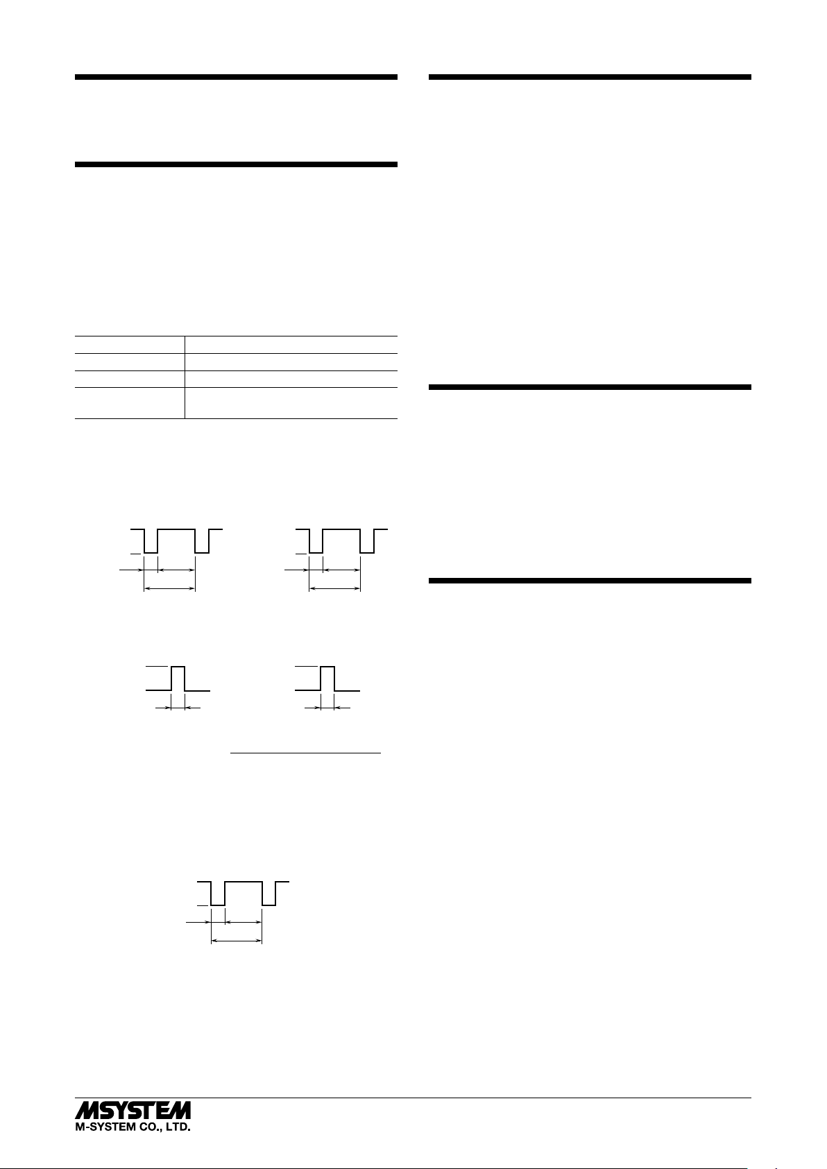
Check also that the receiving instrument is able to accept
the waveform as explained in the figure below.
• Open Collector • Voltage Pulse
OFF
ON
20
%
80
%
1 / f
■Frequency less than 500 Hz at 100% input
➞Duty ratio 20% (See the figure below)
• OUTPUT 2’s Open Collector and Photo MOSFET
Relay Pulse
OFF
ON
20
%
80
%
1 / f
H Level
L Level
20
%
80
%
1 / f
• Open Collector • Voltage Pulse
■Frequency greater than 500 Hz at 100% input
➞See the figure and equation below.
H Level
L Level
Pulse Width
OFF
ON
Pulse Width
Pulse Width [millisec.] = 1
2.09 × 100% Frequency [kHz]
■When OUTPUT 1 is Photo MOSFET Relay Pulse
➞See the figure below. ON pulse width is limited
within 75 ±25 msec. when the output frequency
gets low (below 2 to 4 Hz).
ADJUSTMENT PROCEDURE
This unit is calibrated at the factory to meet the ordered
specifications, therefore you usually do not need any cali-
bration.
For matching the signal to a receiving instrument or in case
of regular calibration, adjust the output as explained in the
following.
■HOW TO CALIBRATE THE OUTPUT SIGNAL
Use a signal source and measuring instruments of sufficient
accuracy level. Turn the power supply on and warm up for
more than 10 minutes.
1) ZERO: Apply 5% input and adjust output to 5%.
2) SPAN: Apply 100% input and adjust output to 100%.
3) Check ZERO adjustment again with 5% input.
4) When ZERO value is changed, repeat the above proce-
dure 1) – 3).
MAINTENANCE
Regular calibration procedure is explained below:
■CALIBRATION
Warm up the unit for at least 10 minutes. Apply 0%, 5%,
25%, 50%, 75% and 100% input signal. Check that the out-
put signal for the respective input signal remains within
accuracy described in the data sheet. When the output is
out of tolerance, recalibrate the unit according to the “AD-
JUSTMENT PROCEDURE” explained earlier.
LIGHTNING SURGE PROTECTION
M-System offers a series of lightning surge protector for
protection against induced lightning surges. Please contact
M-System to choose appropriate models.
10AP
5-2-55, Minamitsumori, Nishinari-ku, Osaka 557-0063 JAPAN
Phone: +81(6)6659-8201 Fax: +81(6)6659-8510 E-mail: info@m-system.co.jp
EM-0851 Rev.5 P. 3 / 3