M8YV / M8YV1
EM-5460 Rev.1P. 2 / 2
TERMINAL CONNECTIONS
Connect the unit as in the diagram below.
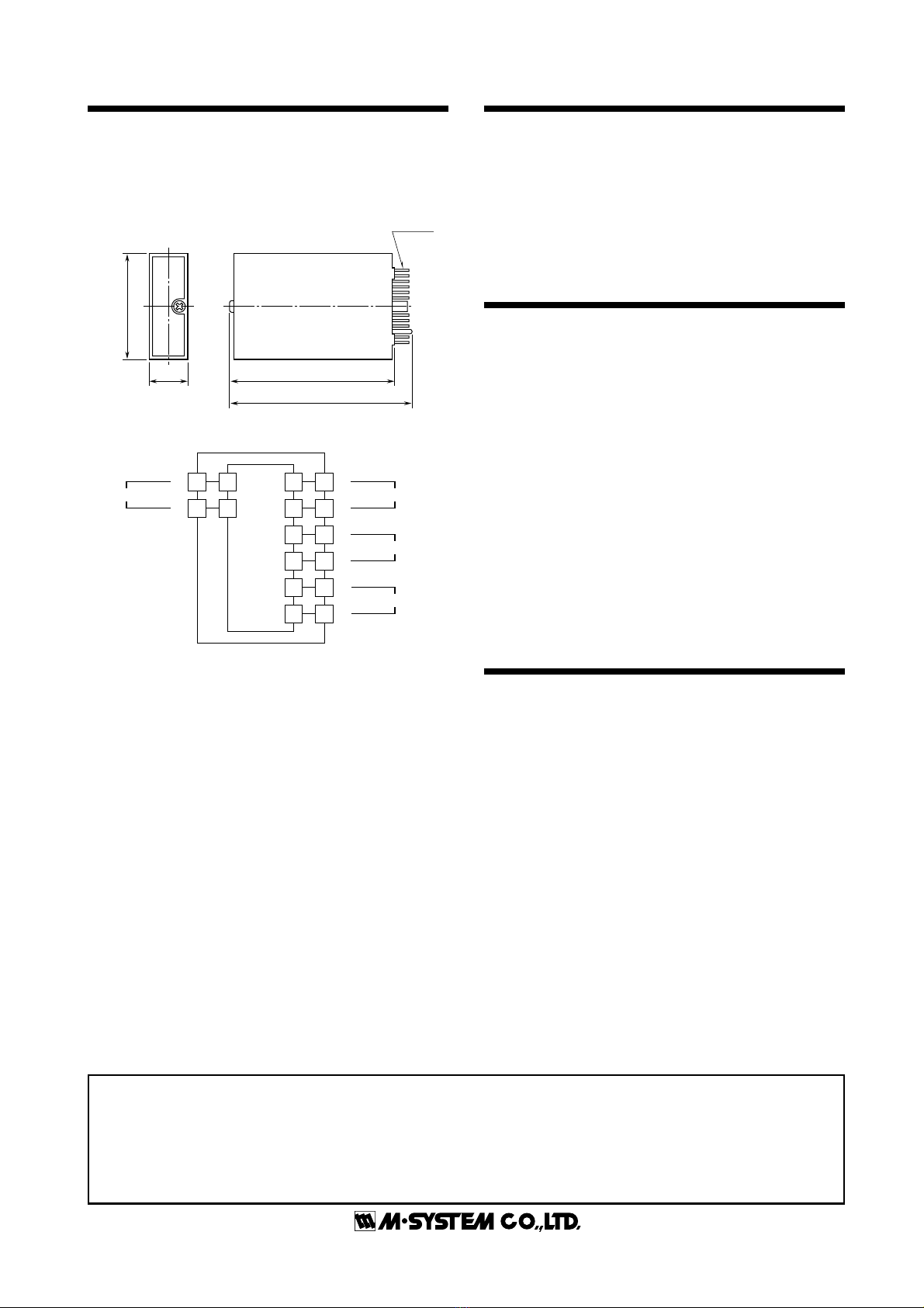
■EXTERNAL DIMENSIONS mm (inch)
■CONNECTION DIAGRAM
M-SYSTEM WARRANTY
M-System warrants such new M-System product which it manufactures to be free from defects in materials and workmanship during the 36-month period following the date that such
productwasoriginallypurchasedifsuchproducthasbeenusedundernormaloperatingconditionsandproperlymaintained,M-System'ssoleliability,andpurchaser'sexclusiveremedies,
under this warranty are, at M-System's option, the repair, replacement or refund of the purchase price of any M-System product which is defective under the terms of this warranty. To
submit a claim under this warranty, the purchaser must return, at its expense, the defective M-System product to the below address together with a copy of its original sales invoice.
THIS IS THE ONLY WARRANTY APPLICABLE TO M-SYSTEM PRODUCT AND IS IN LIEU OF ALL OTHER WARRANTIES, EXPRESS OR IMPLIED, INCLUDING ANY IMPLIED
WARRANTIES OF MERCHANTABILITY OR FITNESS FOR A PARTICULAR PURPOSE. M-SYSTEM SHALL HAVE NO LIABILITY FOR CONSEQUENTIAL, INCIDENTAL OR
SPECIAL DAMAGES OF ANY KIND WHATSOEVER.
M-System
Co.,
Ltd.,
5-2-55,
Minamitsumori,
Nishinari-ku,
Osaka
557-0063
JAPAN,
Phone:
(06)
6659-8201,
Fax:
(06)
6659-8510,
E-mail:
[email protected]+
–
Installation Base
OUTPUT 1
6
7
8
9
10
11
+
–
+
–
OUTPUT 2
1
2
A
B
POWER
+
–
INPUT
I/O PINS
17.5(.69)
48 (1.89)
75 (2.95)
83 (3.27)
CHECKING
1) Terminal wiring: Check that all cables are correctly
connected according to the connection diagram.
2) Power input: Check the power input voltage.
3) Input: Check that the input signal is within 0 – 100% of
the full-scale.
4) Output: Check that the load resistance meets the de-
scribed specifications.
ADJUSTMENT PROCEDURE
This unit is calibrated at the factory to meet the ordered
specifications,thereforeyou usuallydonot needanycalibra-
tion.
For matching the signal to a receiving instrument or in case
of regular calibration, adjust the output as explained in the
following.
■ HOW TO CALIBRATE THE OUTPUT SIGNAL
Use a signal source and measuring instruments of sufficient
accuracy level. Turn the power supply on and warm up for
more than 10 minutes.
(Output 1 and Output 2 are linked.)
1) ZERO: Apply 0% input and adjust output to 0%.
2) SPAN: Apply 100% input and adjust output to 100%.
3) Check ZERO adjustment again with 0% input.
4) WhenZEROvalueischanged,repeattheaboveprocedure
1) – 3).
MAINTENANCE
Regular calibration procedure is explained below:
■ CALIBRATION
Warm up the unit for at least 10 minutes. Apply 0%, 25%,
50%, 75% and 100% input signal. Check that the output
signal for the respective input signal remains within accu-
racy described in the data sheet. When the output is out of
tolerance, recalibrate the unit according to the "ADJUST-
MENT PROCEDURE" explained earlier.


