manuals.online logo
Brands
  1. Home
  2. •
  3. Brands
  4. •
  5. M-system
  6. •
  7. Media Converter
  8. •
  9. M-system KDA3 User manual

M-system KDA3 User manual

KDA3
P. 1 / 5 EM-3646 Rev.2
BEFORE USE ....
Thank you for choosing M-System. Before use, please check
contents of the package you received as outlined below.
If you have any problems or questions with the product,
please contact M-System's Sales Office or representatives.
■ PACKAGE INCLUDES:
Signal conditioner (body + base socket) ..................... (1)
■ MODEL NO.
Check that model No. described on specification label is
exactly what you ordered.
■ INSTRUCTION MANUAL
This manual describes necessary points of caution when you
use this product, including installation, connection and basic
maintenance procedures.
When you need to change software settings, please refer to
the Operation Manual for Model PU-2❑(EM-9255), Section
A.
POINTS OF CAUTION
■ POWER INPUT RATINGS
• Operational range & power consumption: Check the power
rating for the unit on the specification label.
Rating 100 – 240V AC: 85 – 264V, 47 – 66 Hz, approx. 8VA
Rating 12 – 24V DC: 10.8 – 26.4V, approx. 4W
Rating 110V DC: 85 – 150V, approx. 4W
• Power fuse: A power fuse of the rating as shown below is
incorporated for safety. However, DO NOT replace it by the
user.
AC rating and 110V DC: T 0.5A 250V
DC rating except 110V DC: T 1A 250V
■ UNPLUGGING THE UNIT
• Before you remove the unit from its base socket or mount it,
turn off the power supply and signal input for safety.
■ ENVIRONMENT
• Indoor use
• When heavy dust or metal particles are present in the air,
install the unit inside proper housing with sufficient ventila-
tion.
• Do not install the unit where it is subjected to continuous
vibration. Do not subject the unit to physical impact.
• Environmental temperature must be within -5 to +55°C (23
to 131°F) with relative humidity within 30 to 90% RH in order
to ensure adequate life span and operation.
■ WIRING
• Do not install cables (power supply, input and output) close
to noise sources (relay drive cable, high frequency line, etc.).
• Do not bind the unit's cables together with cables where
high noise levels are present. Do not install them in the same
duct.
INSTRUCTION MANUAL
MODEL KDA3
D/A CONVERTER
(16-bit resolution
; programmable with programming unit)
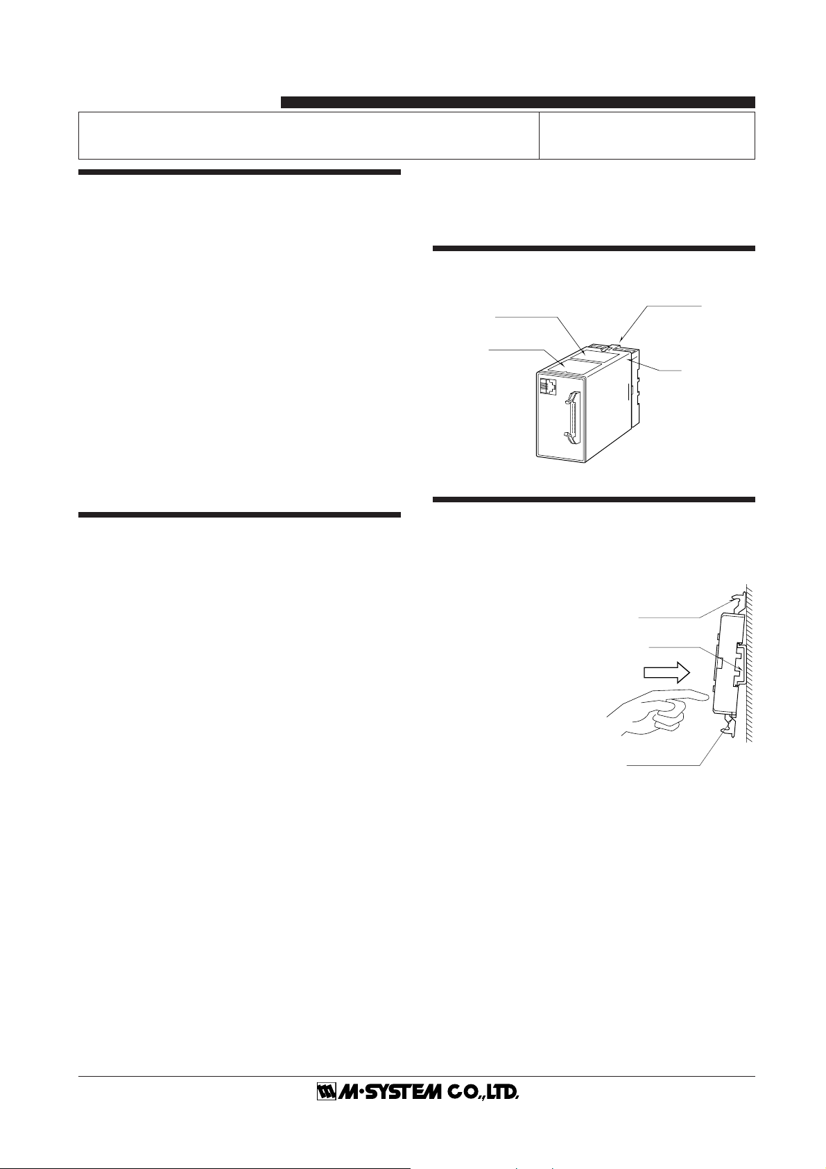
Body
Base Socket
Specification
Label
Connection
Diagram Label
■ AND ....
• The unit is designed to function as soon as power is
supplied, however, a warm up for 10 minutes is required for
satisfying complete performance described in the data sheet.
COMPONENT IDENTIFICATION
INSTALLATION
Detach the yellow clamps located at the top and bottom of the
unit for separating the body from the base socket.
■ DIN RAIL MOUNTING
Set the base socket so that its
DIN rail adaptor is at the bot-
tom. Position the upper hook
at the rear side of base socket
on the DIN rail and push in the
lower. When removing the
socket, push down the DIN rail
adaptor utilizing a minus
screwdriver and pull.
■ WALL MOUNTING
Refer to the drawings in the
“TERMINAL CONNECTION”
section.
Clamp
(top & bottom)
DIN Rail
35mm wide
Spring Loaded
DIN Rail Adaptor
Shape and size of the base socket
are slightly different with various
socket types.
KDA3
P. 2 / 5 EM-3646 Rev.2
FRONT PANEL CONFIGURATION & PROGRAMMING WITH PU-2❑
• Response Messages
OK: OK
NG: No good. Check modular jack connection.
ER: Communication error
26-pin Connector
(Pin Assignments)
12
25 26
Modular Jack
G
ITEM No.
I()
D
Response Messages
Data to be entered
or Messages
LCD Display
MDF.
CODE
ITEM INPUT DATA EXAMPLE (DEFAULT) CONTENTS
01 S 0, 1 MNTSW : MON MODE Modification code
0:Data indication only.
1:All parameters are modifiable.
02 D STATUS : 0 Status indication
03 D Output type
DEVICE : 0 0 : V1
DEVICE : 1 1 : V2
DEVICE : 2 2 : Z1
04 P 0 – 99 POWONDELAY : 5 Power ON-delay time (seconds)
10 D -15.0 – 115.0 %PV : XXX.X Output indicated in % (as set in ITEM 26/27)
11 P -99.99 – 99.99 ZERO : 0.00 Zero adjustment (%) (fine adj. of the value set in ITEM 26)
12 P -99.99 – 99.99 SPAN : 0.00 Span adjustment (%) (fine adj. of the value set in ITEM 27)
13 D PV : YYYY Output indicated in engineering unit (as scaled in ITEM 14/15)
14 P -9999 – 9999 SCALE 0 : -9999 BCD Scaled range 0% *1
15 P -9999 – 9999 SCALE 1000 : 9999 Scaled range 100% *1
14 P -7FFF – 7FFF SCALE 0 : -7FFF Binary Scaled range 0% *1
15 P -7FFF – 7FFF SCALE 100 : 7FFF Scaled range 100% *1
14 P 0000 – FFFF SCALE 0 : 0000 Offset binary Scaled range 0% *1
15 P 0000 – FFFF SCALE 100 : FFFF Reflected binary Scaled range 100% *1
14 P 8000 – 7FFF SCALE 0 : 8000
Two's complement
Scaled range 0% *1
15 P 8000 – 7FFF SCALE 100 : 7FFF Scaled range 100% *1
17 P 0, 1, 2, 3, 4 CODE : 0 Input code 0 : BCD with polarity (decimal)
1 : Binary with polarity
2 : Offset binary
3 : Two’s complement
4 : Relfected binary
18 P 0, 1, 2, 3, 4 AV1L_BIT : 0 Available number of bits
0: 16 bits 1: 14 bits 2: 12 bits 3: 10 bits 4: 8 bits
19 P 0, 1 POLAR : 1 POL input 0 : Unavailable (not used)
1 : Available (used)
20 P 0, 1 DATA_LOGIC : 1 Data input logic*20 : Positive
1 : Negative
21 P 0, 1, 2 LOAD_LOGIC : 0 LOAD input 0 : LOAD at Low or shortcircuit*3
1 : LOAD at High or opencircuit*4
2 : Unavailable (not used)
22 P 0, 1 POLAR_LOGIC : 1 POL input 0 : Negative at High or opencircuit*4
1 : Negative at Low or shortcircuit*3
23 P 0, 1, 2 PARITY : 0 Parity check 0 : Disable
1 : Enable Parity per each digit
2 : Enable Parity for all digits
24 P 0, 1 PARITY_TYPE : 0 Odd or even parity 0 : Odd
1 : Even
25 P 0.0 – 60.0 LAG_TIME : 0.0 Delay buffer (seconds, 0 – 90%)
When the Response Time model suffix code is specified to 1, the set
value is only effective at 5.0 or higher value.
KDA3
P. 3 / 5 EM-3646 Rev.2
3456
2187
80 (3.15)
50 (1.97) 103 (4.06)
123 (4.84) [3.3 (.13)]
80 (3.15)
20
(.79)
35.4 (1.39)
40 (1.57)
50 (1.97)
7.8 (.31)
CLAMP
(top & bottom)
DIN RAIL
35mm wide
2–4.5 (.18) dia.
MTG HOLE
15 (.59) deep
8–M3.5
SCREW
•When mounting, no extra space is needed between units.
16
(.63)
55 (2.17) min.
■ DIMENSIONS mm (inch)
TERMINAL CONNECTIONS
Connect the unit as in the diagram below or refer to the connection diagram label on top of the unit.
26 P -1.00 – 1.00 ZERO : -1.00 Output code V1 0% output voltage (V) *5
27 P -1.00 – 1.00 SPAN : 1.00 100% output voltage (V) *5
26 P -10.0 – 10.0 ZERO : -10.00 Output code V2 0% output voltage (V) *5
27 P -10.0 – 10.0 SPAN : 10.00 100% output voltage (V) *5
26 P 0.0 – 24.0 ZERO : 4.00 Output code Z1 0% output current (mA) *5
27 P 0.0 – 24.0 SPAN : 20.00 100% output current (mA) *5
28 N/A – DA3_VER : *.** ROM version
*1: Of the range set in ITEM 14/15. ITEM 14 < ITEM 15. Set after ITEM 17 and 18.
*2: Open collector input logic
*3: “Opencircuit” with 24V DC input
*4: “Shortcircuit” with 24V DC input
*5: ITEM 26 < ITEM 27.
Modification Code
D:No modification (writing) possible. Used only for monitoring (reading).
S:Modifiable at any time.
P:Modifiable only when the MAINTENANCE SWITCH is in the “PRG” mode.
ITEM INPUT DATA EXAMPLE (DEFAULT) CONTENTS
MDF.
CODE
LOGIC ITEM 10 0 : Positive logic 1 : Negative logic
INPUT DATA 0 1 0 1
TTL level, open collector sink type Short Open Open Short
(TTL level) (LOW) (HIGH) (HIGH) (LOW)
24V DC, open collector source type Open Short Short Open
KDA3
P. 4 / 5 EM-3646 Rev.2
■ CONNECTION DIAGRAM
INPUT CONNECTOR (26-pin)
■ BCD INPUT ■ BINARY, TWO'S COMPLEMENT INPUTS
PIN NO. ASSIGNMENT PIN NO. ASSIGNMENT
11×10017 COM (–)
22×10018 COM (–)
34×10019 No connection
48×10020 POL
51×10121 LOAD *1
62×10122 LOAD *1
74×10123 P0 *2
88×10124 P1
91×10225 P2
10 2 ×10226 P3
11 4 ×10²
12 8 ×10²
13 1 ×10³
14 2 ×10³
15 4 ×10³
16 8 ×103
*1. Pin No. 21 and 22 are internally connected.
*2. P0corresponds to n ×100, P1to n ×101, P2 to n ×102, P3 to n
×103. Only P0corresponds when the parity for all digits are
valid.
Note: With the number of bits set to 14 (or 12, 10, 8) with
ITEM 18, Pin No. 1 – 14 (or 1 – 12, 1 – 10, 1 – 8) are valid.
PIN NO. ASSIGNMENT PIN NO. ASSIGNMENT
1B
017 COM (–)
2B
118 COM (–)
3B
219 No connection
4B
320 POL
5B
421 LOAD *1
6B
522 LOAD *1
7B
623 P0 *2
8B
724 P1
9B
825 P2
10 B926 P3
11 B10
12 B11
13 B12
14 B13
15 B14
16 B15
*1. Pin No. 21 and 22 are internally connected.
*2. P 0 corresponds to B0through B3, P1to B4through B7, P2 to
B8through B11, P3 to B12 through B15. Only P0corresponds
when the parity for all digits are valid.
Note: With the number of bits set to 14 (or 12, 10, 8) with
ITEM 18, Pin No. 1 – 14 (or 1 – 12, 1 – 10, 1 – 8) are valid.
U(+)
V(–) POWER
7
8
PU-2
❑
MODULAR JACK
PU-2
❑
MODULAR JACK
+
–
OUTPUT
1
2
INPUT
CONNECTOR
■Input Connection Examples
• Standard type
TTL level • Option /A
24V DC
PLC DA3 DA3 DA3
5V
Open collector, sink type
PLC
24V
PLC
CONNECTOR
CONNECTOR
CONNECTOR
TIMING CHART
LOAD INPUT
DATA INPUT
The unit reads data upon detecting a change of LOAD input status.
DO NOT change LOAD input setting when the data input logic is changed.
10 ms min.
1 ms min.
• Example: TTL Level Input (factory setting)
KDA3
P. 5 / 5 EM-3646 Rev.2
M-SYSTEM WARRANTY
M-System warrants such new M-System product which it manufactures to be free from defects in materials and workmanship during the 36-month period following the date that such
productwasoriginallypurchasedifsuchproducthasbeenusedundernormaloperatingconditionsandproperlymaintained,M-System'ssoleliability,andpurchaser'sexclusiveremedies,
under this warranty are, at M-System's option, the repair, replacement or refund of the purchase price of any M-System product which is defective under the terms of this warranty. To
submit a claim under this warranty, the purchaser must return, at its expense, the defective M-System product to the below address together with a copy of its original sales invoice.
THIS IS THE ONLY WARRANTY APPLICABLE TO M-SYSTEM PRODUCT AND IS IN LIEU OF ALL OTHER WARRANTIES, EXPRESS OR IMPLIED, INCLUDING ANY IMPLIED
WARRANTIES OF MERCHANTABILITY OR FITNESS FOR A PARTICULAR PURPOSE. M-SYSTEM SHALL HAVE NO LIABILITY FOR CONSEQUENTIAL, INCIDENTAL OR
SPECIAL DAMAGES OF ANY KIND WHATSOEVER.
M-System Co., Ltd., 5-2-55, Minamitsumori, Nishinari-ku, Osaka 557-0063 JAPAN, Phone: (06) 6659-8201, Fax: (06) 6659-8510, E-mail: [email protected]
CHECKING
1) Terminal wiring: Check that all cables are correctly
connected according to the connection diagram.
2) Power input voltage: Check voltage across the terminal 7
–8with a multimeter.
3) Input: Dry contact or open collector. Check the input
device meets the following requirements.
TTL level
Sensing: 5V DC @1mA
Threshold voltage of the input circuit: 1V DC
24V DC
Sensing: 24V DC @3.5mA
Threshold voltage of the input circuit: 3V DC
LOAD signal: ON time 1 millisec. min.
4) Output: Check that the load resistance meets the de-
scribed specifications.
INPUT-OUTPUT RELATION EXAMPLE
■ BCD, BINARY (WITH POLARITY)
MSBPOL
POLARITY
DATA
LSB
–FS
–
OR OR
0
DIGITAL INPUT
+FS + ANALOG OUTPUT
■ TWO'S COMPLEMENT
MSBPOL
UNUSED
DATA
LSB
–FS
–
OR OR
0
DIGITAL INPUT
+FS + ANALOG OUTPUT
■ OFFSET BINARY
MSB
POLARITY
POL
UNUSED
DATA
LSB
–FS
–OR
OR
0
DIGITAL INPUT
+FS + ANALOG OUTPUT
POL available not available
LIGHTNING PROTECTION
In order to protect the unit from lightning surges entering
through power supply cables, use of appropriate lightning
surge protectors are recommended. Please contact M-Sys-
tem.

Other M-system Media Converter manuals

M-system JAPD User manual

M-system

M-system JAPD User manual

M-system 18MS User manual

M-system

M-system 18MS User manual

M-system JARP2 User manual

M-system

M-system JARP2 User manual

M-system Mini-M M2AP User manual

M-system

M-system Mini-M M2AP User manual

M-system AD3V User manual

M-system

M-system AD3V User manual

M-system M8RS User manual

M-system

M-system M8RS User manual

M-system JPR2 User manual

M-system

M-system JPR2 User manual

M-system 18KVS User manual

M-system

M-system 18KVS User manual

M-system M8RS1 User manual

M-system

M-system M8RS1 User manual

M-system 18PE User manual

M-system

M-system 18PE User manual

M-system M8BS-16U0 User manual

M-system

M-system M8BS-16U0 User manual

M-system 17TG User manual

M-system

M-system 17TG User manual

M-system 18KRS User manual

M-system

M-system 18KRS User manual

M-system 15RS User manual

M-system

M-system 15RS User manual

M-system JPR2 User manual

M-system

M-system JPR2 User manual

M-system W2AP User manual

M-system

M-system W2AP User manual

M-system JAPD2 User manual

M-system

M-system JAPD2 User manual

M-system 18KTS User manual

M-system

M-system 18KTS User manual

M-system 18KJM User manual

M-system

M-system 18KJM User manual

M-system M8AP User manual

M-system

M-system M8AP User manual

M-system 18JV User manual

M-system

M-system 18JV User manual

M-system Mini-M M2RR User manual

M-system

M-system Mini-M M2RR User manual

M-system 18TG User manual

M-system

M-system 18TG User manual

M-system 18TS User manual

M-system

M-system 18TS User manual

Popular Media Converter manuals by other brands

TRENDnet TFC-110S15I - Media Converter - External Specifications

TRENDnet

TRENDnet TFC-110S15I - Media Converter - External Specifications

Moxa Technologies TCF-142-S-ST-RM Quick installation guide

Moxa Technologies

Moxa Technologies TCF-142-S-ST-RM Quick installation guide

Extron electronics SMD 101 user guide

Extron electronics

Extron electronics SMD 101 user guide

AJA DRM-R1 Installation & operation guide

AJA

AJA DRM-R1 Installation & operation guide

LAWO V_pro8 Installation & operation manual

LAWO

LAWO V_pro8 Installation & operation manual

Procentec VPGate manual

Procentec

Procentec VPGate manual

Sencore OmniHub 6RFX user manual

Sencore

Sencore OmniHub 6RFX user manual

l-com LC-MCGSFP user manual

l-com

l-com LC-MCGSFP user manual

Leviton NPC DHV user guide

Leviton

Leviton NPC DHV user guide

RKC INSTRUMENT COM-JH instruction manual

RKC INSTRUMENT

RKC INSTRUMENT COM-JH instruction manual

Auralic ALTAIR G1 user guide

Auralic

Auralic ALTAIR G1 user guide

Musical Fidelity V-LINK 192 instructions

Musical Fidelity

Musical Fidelity V-LINK 192 instructions

Vertiv eSure C48/58-1000 installation manual

Vertiv

Vertiv eSure C48/58-1000 installation manual

Ltech LT- 830 manual

Ltech

Ltech LT- 830 manual

ADF Web HD67643-A1 user manual

ADF Web

ADF Web HD67643-A1 user manual

Siemens SINAMICS DCM operating instructions

Siemens

Siemens SINAMICS DCM operating instructions

Buffalo AirStation WLI-TX4-G54HP user manual

Buffalo

Buffalo AirStation WLI-TX4-G54HP user manual

evertz 7700 Series manual

evertz

evertz 7700 Series manual

manuals.online logo
manuals.online logoBrands
  • About & Mission
  • Contact us
  • Privacy Policy
  • Terms and Conditions

Copyright 2025 Manuals.Online. All Rights Reserved.