manuals.online logo
Brands
  1. Home
  2. •
  3. Brands
  4. •
  5. M-system
  6. •
  7. Power Supply
  8. •
  9. M-system R3-PS3 User manual

M-system R3-PS3 User manual

Other M-system Power Supply manuals

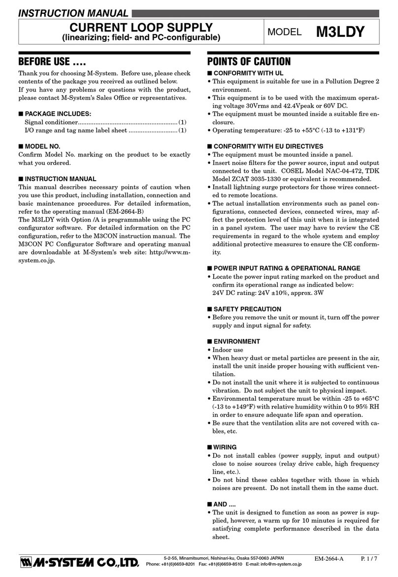
M-system Current Loop Supply M3LDY User manual

M-system

M-system Current Loop Supply M3LDY User manual

M-system 10DNY User manual

M-system

M-system 10DNY User manual

M-system R5-PS1 User manual

M-system

M-system R5-PS1 User manual

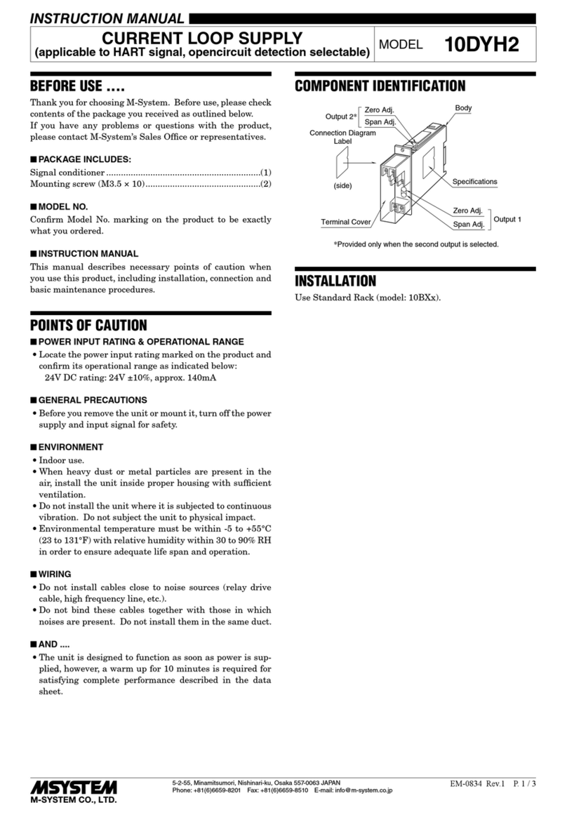
M-system 10DYH2 User manual

M-system

M-system 10DYH2 User manual

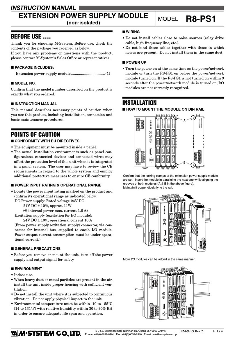
M-system R8-PS1 User manual

M-system

M-system R8-PS1 User manual

M-system JPS3 User manual

M-system

M-system JPS3 User manual

M-system M5DY-5-M User manual

M-system

M-system M5DY-5-M User manual

M-system W2DYH2 User manual

M-system

M-system W2DYH2 User manual

M-system M5D User manual

M-system

M-system M5D User manual

M-system Mini-M M2DYS User manual

M-system

M-system Mini-M M2DYS User manual

M-system R3S-YV4 User manual

M-system

M-system R3S-YV4 User manual

M-system 18KDYH2 User manual

M-system

M-system 18KDYH2 User manual

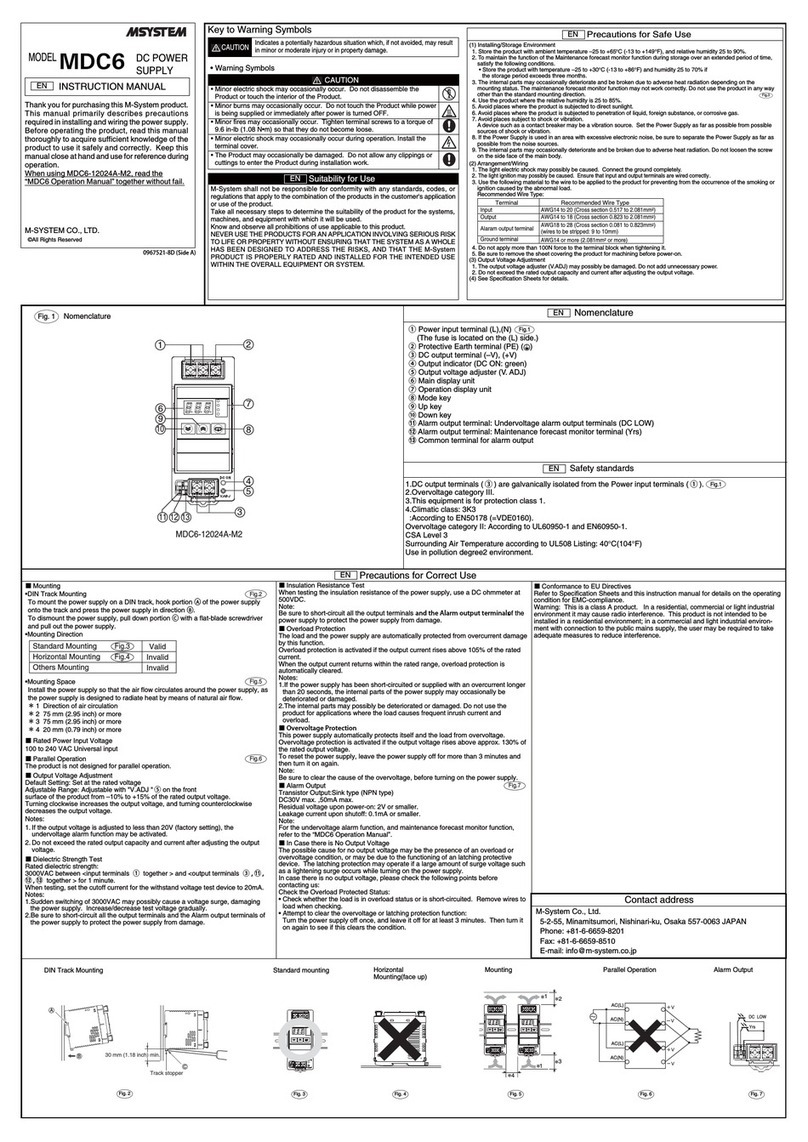
M-system MDC6 User manual

M-system

M-system MDC6 User manual

M-system MDC5 User manual

M-system

M-system MDC5 User manual

M-system MDC User manual

M-system

M-system MDC User manual

M-system M5TS Series User manual

M-system

M-system M5TS Series User manual

M-system Mini-M M2DYH User manual

M-system

M-system Mini-M M2DYH User manual

M-system 18DU User manual

M-system

M-system 18DU User manual

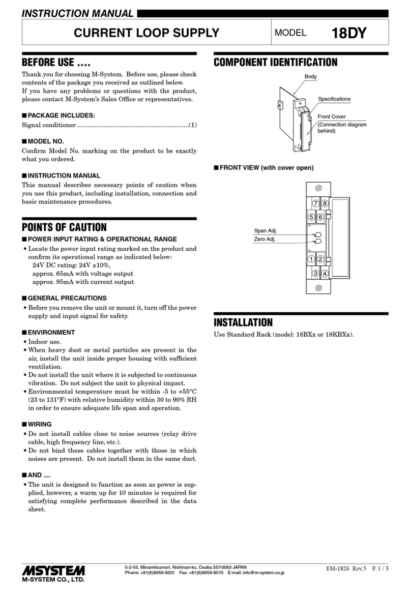
M-system 18DY User manual

M-system

M-system 18DY User manual

M-system 10DU User manual

M-system

M-system 10DU User manual

M-system M5DY User manual

M-system

M-system M5DY User manual

M-system KWDNY User manual

M-system

M-system KWDNY User manual

M-system 18KDY User manual

M-system

M-system 18KDY User manual

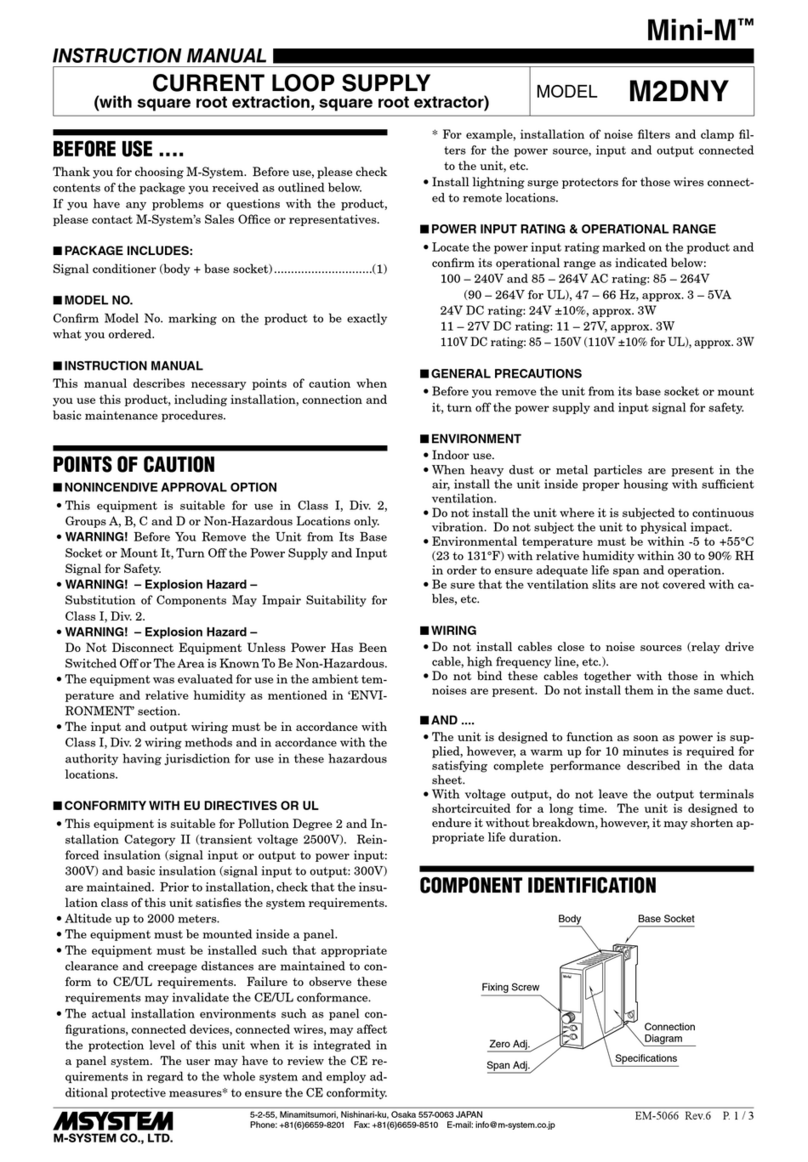
M-system Mini-M M2DNY User manual

M-system

M-system Mini-M M2DNY User manual

Popular Power Supply manuals by other brands

Videx 520MR Installation instruction

Videx

Videx 520MR Installation instruction

Poppstar 1008821 Instructions for use

Poppstar

Poppstar 1008821 Instructions for use

TDK-Lambda LZS-A1000-3 Installation, operation and maintenance manual

TDK-Lambda

TDK-Lambda LZS-A1000-3 Installation, operation and maintenance manual

TDK-Lambda 500A instruction manual

TDK-Lambda

TDK-Lambda 500A instruction manual

Calira EVS 17/07-DS/IU operating instructions

Calira

Calira EVS 17/07-DS/IU operating instructions

Monacor PS-12CCD instruction manual

Monacor

Monacor PS-12CCD instruction manual

VOLTIMA MagicBox 15 Installation and operating instructions

VOLTIMA

VOLTIMA MagicBox 15 Installation and operating instructions

Miller Auto Deltaweld 452 owner's manual

Miller

Miller Auto Deltaweld 452 owner's manual

BCP PUOUBK How to install

BCP

BCP PUOUBK How to install

HC 2210 manual

HC

HC 2210 manual

Agilent Technologies 6032A Service manual

Agilent Technologies

Agilent Technologies 6032A Service manual

Radial Engineering SB-48UB user guide

Radial Engineering

Radial Engineering SB-48UB user guide

Puls CT5.241 installation manual

Puls

Puls CT5.241 installation manual

OCZ ZX1250W Technical specifications

OCZ

OCZ ZX1250W Technical specifications

iseg ECH 238 manual

iseg

iseg ECH 238 manual

Agilent Technologies 6631B Service manual

Agilent Technologies

Agilent Technologies 6631B Service manual

Power XXL A Series instruction manual

Power

Power XXL A Series instruction manual

HP 6200B Operating and service manual

HP

HP 6200B Operating and service manual

manuals.online logo
manuals.online logoBrands
  • About & Mission
  • Contact us
  • Privacy Policy
  • Terms and Conditions

Copyright 2025 Manuals.Online. All Rights Reserved.

5-2-55, Minamitsumori, Nishinari-ku, Osaka 557-0063 JAPAN
Phone: +81(6)6659-8201 Fax: +81(6)6659-8510 E-mail: info@m-system.co.jp
EM-8358 Rev.6 P. 1 / 2
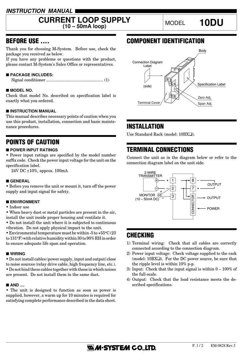
INSTRUCTION MANUAL
POWER SUPPLY MODULE
(double slot, continuous output current 2.0 A) MODEL R3-PS3
BEFORE USE ....
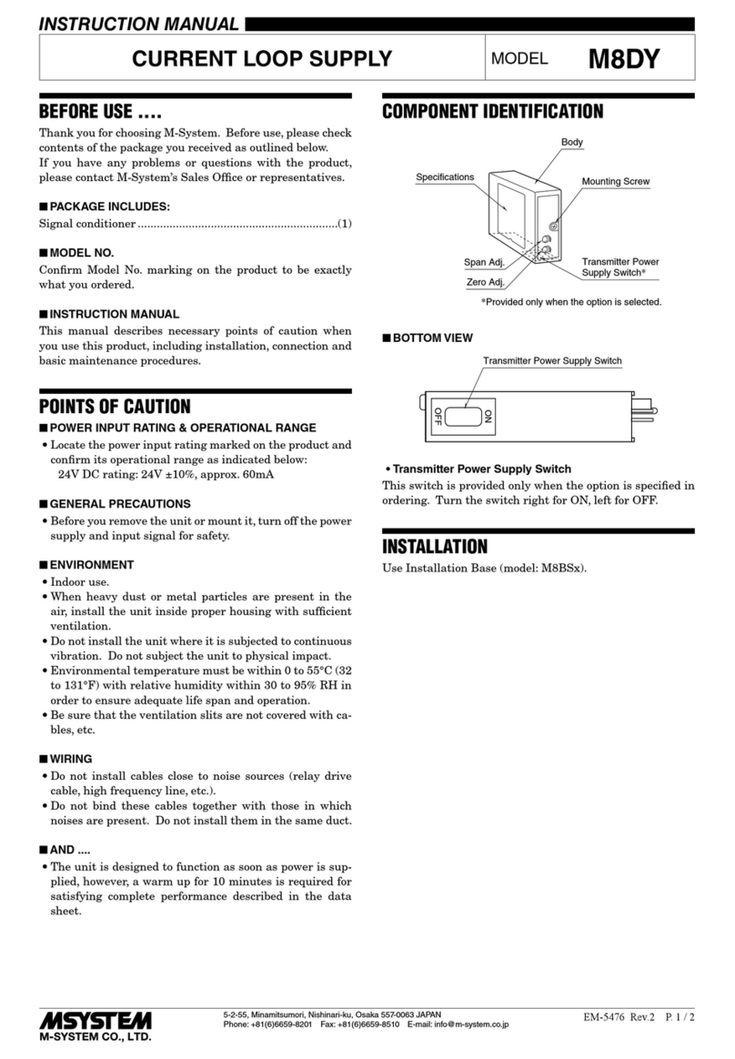
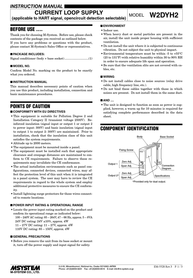
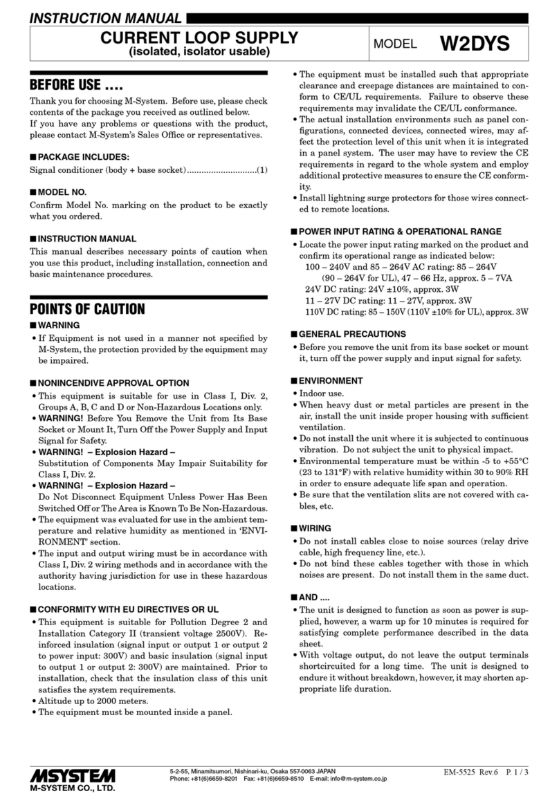
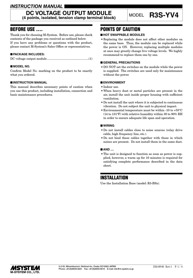
Thank you for choosing M-System. Before use, please check
contents of the package you received as outlined below.
If you have any problems or questions with the product,
please contact M-System’s Sales Office or representatives.
■PACKAGE INCLUDES:
Power supply module ..........................................................(1)
■MODEL NO.
Confirm Model No. marking on the product to be exactly
what you ordered.
■INSTRUCTION MANUAL
This manual describes necessary points of caution when
you use this product, including installation, connection and
basic maintenance procedures.
POINTS OF CAUTION
■CONFORMITY WITH EU DIRECTIVES
• This equipment is suitable for Pollution Degree 2, Meas-
urement category II (RUN contact output, transient volt-
age 2500V) and Installation Category II (transient volt-
age 2500V). Reinforced insulation (internal power to
power input: 300V) and basic insulation (internal power
to RUN contact output: 300V) are maintained. Prior to
installation, check that the insulation class of this unit
satisfies the system requirements.
• Altitude up to 2000 meters.
• The equipment must be mounted inside the instrument
panel of a metal enclosure.
• The equipment must be installed such that appropriate
clearance and creepage distances are maintained to con-
form to CE requirements. Failure to observe these re-
quirements may invalidate the CE conformance.
• The actual installation environments such as panel con-
figurations, connected devices, connected wires, may af-
fect the protection level of this unit when it is integrated
in a panel system. The user may have to review the CE
requirements in regard to the whole system and employ
additional protective measures to ensure the CE conform-
ity.
■POWER INPUT RATING & OPERATIONAL RANGE
• Locate the power input rating marked on the product and
confirm its operational range as indicated below:
85 – 132V AC rating: 85 – 132V, 47 – 66 Hz, approx. 100VA
100 – 120V AC rating: 85 – 132V, 47 – 66 Hz, approx. 100VA
170 – 264V AC rating: 170 – 264V, 47 – 66 Hz, approx. 100VA
200 – 270V AC rating: 170 – 264V, 47 – 66 Hz, approx. 100VA
24V DC rating: 24V ±10%, approx. 50W or 2.0A at 24V
110V DC rating: 85 – 150V, approx. 50W or 440mA at 110V
■GENERAL PRECAUTIONS
• Before you remove the unit from its base or mount it, turn
off the power supply for safety.
■ENVIRONMENT
• Indoor use.
• When heavy dust or metal particles are present in the
air, install the unit inside proper housing with sufficient
ventilation.
• Do not install the unit where it is subjected to continuous
vibration. Do not subject the unit to physical impact.
• Environmental temperature must be within -10 to +55°C
(14 to 131°F) with relative humidity within 30 to 90% RH
in order to ensure adequate life span and operation.
■WIRING
• Do not install cables close to noise sources (relay drive
cable, high frequency line, etc.).
• Do not bind these cables together with those in which
noises are present. Do not install them in the same duct.
■AND ....
• The unit is designed to function as soon as power is sup-
plied, however, a warm up for 10 minutes is required for
satisfying complete performance described in the data
sheet.
INSTALLATION
Use the Installation Base (model: R3-BSx).
For heat dissipation, install the power supply module into
the rightmost slot or leftmost slot. For redundant power
system, install two modules in series into the rightmost slot
or leftmost slot. If there is no problem, the rightmost slot
is recommended.
In case of redundant power system use, be sure to install
two same current capacity power supply modules (model:
R3-PS3) in series. The combination of different current ca-
pacity power supply module or interface module with power
supply is not available.
COMPONENT IDENTIFICATION
■FRONT VIEW
1
2
3
4
5
6
Power LED
Power LED: Green LED turns on when the power is sup-
plied.
R3-PS3
5-2-55, Minamitsumori, Nishinari-ku, Osaka 557-0063 JAPAN
Phone: +81(6)6659-8201 Fax: +81(6)6659-8510 E-mail: info@m-system.co.jp
EM-8358 Rev.6 P. 2 / 2
TERMINAL CONNECTIONS
Connect the unit as in the diagram below.
■EXTERNAL DIMENSIONS unit: mm (inch)
1
2
3
4
5
6
130 (5.12)
55 (2.17)
POSITIONING
GUIDE
TERMINAL
COVER
6–M3
SCREW
6.2
(.24)
109 (4.29)
90 (3.54)19 (.75)
■ STANDARD TYPE
■ OPTION /B
■CONNECTION DIAGRAM
INTERNAL
POWER
2
3
6
U (+)
V (–)
*FG
POWER INPUT
BUS CONNECTOR
1
4
RUN +
RUN –
RUN CONTACT
OUTPUT
*In order to improve EMC performance, bond the FG terminal to the ground.
Caution: This terminal is NOT a protective conductor terminal.
WIRING INSTRUCTIONS
■SCREW TERMINAL
Torque: 0.5 N·m
■SOLDERLESS TERMINAL
Refer to the drawing below for recommended ring tongue
terminal size. Spade tongue type is also applicable. Solder-
less terminals with insulation sleeve do not fit.
Applicable wire size: 0.75 – 1.25 mm2
Recommended manufacturer: Japan Solderless Terminal
MFG. Co., Ltd., Nichifu Co., Ltd.
12max
6max
3max 4min
3.2 dia.
(mm)