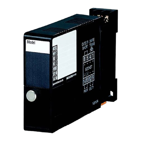
M-system R3-GE1 User manual

5-2-55, Minamitsumori, Nishinari-ku, Osaka 557-0063 JAPAN
Phone: +81(6)6659-8201 Fax: +81(6)6659-8510 E-mail: info@m-system.co.jp
EM-8464 Rev.7 P. 1 / 7
INSTRUCTION MANUAL
ETHERNET INTERFACE MODULE
(Modbus/TCP) MODEL R3-GE1
BEFORE USE ....
Thank you for choosing M-System. Before use, please check
contents of the package you received as outlined below.
If you have any problems or questions with the product,
please contact M-System’s Sales Office or representatives.
■PACKAGE INCLUDES:
Network interface module ..................................................(1)
■MODEL NO.
Confirm Model No. marking on the product to be exactly
what you ordered.
■INSTRUCTION MANUAL
This manual describes necessary points of caution when
you use this product, including installation, connection and
basic maintenance procedures.
POINTS OF CAUTION
■CONFORMITY WITH EU DIRECTIVES
• The equipment must be mounted inside the instrument
panel of a metal enclosure.
• The actual installation environments such as panel con-
figurations, connected devices, connected wires, may af-
fect the protection level of this unit when it is integrated
in a panel system. The user may have to review the CE
requirements in regard to the whole system and employ
additional protective measures to ensure the CE conform-
ity.
■HOT SWAPPABLE MODULES
• The module can be replaced while the power is ON. Be
sure to replace it when the module is not communicat-
ing with a host, as it may affect the system. Replacing
multiple modules at once may greatly change line voltage
levels. We highly recommend to replace them one by one.
■GENERAL PRECAUTIONS
• DO NOT set the switches on the module while the power
is supplied. The switches are used only for maintenance
without the power.
■ENVIRONMENT
• Indoor use.
• When heavy dust or metal particles are present in the
air, install the unit inside proper housing with sufficient
ventilation.
• Do not install the unit where it is subjected to continuous
vibration. Do not apply physical impact to the unit.
• Environmental temperature must be within -10 to +55°C
(14 to 131°F) with relative humidity within 30 to 90% RH
in order to ensure adequate life span and operation.
■WIRING
• Do not install cables close to noise sources (relay drive
cable, high frequency line, etc.).
• Do not bind these cables together with those in which
noises are present. Do not install them in the same duct.
■AND ....
• The unit is designed to function as soon as power is sup-
plied, however, a warm up for 10 minutes is required for
satisfying complete performance described in the data
sheet.
INSTALLATION
Use the Installation Base Model: R3-BS, or Model: R3-BSW
for free I/O address capability.
Before mounting the Network Interface Module R3-GE1
onto the base, be sure to configure the module as explained
below.
■MODULE ALLOCATION
Use the side DIP SW1 to set the number of slots which the
module is assigned to.
See “TRANSMISSION DATA DESCRIPTIONS.”
■NETWORK SLOTS ON THE BASE
I/O 1 I/O 2 I/O n
With Model R3-BS base, mount the I/O Modules from the
left end (I/O 1) to the right in order that the Network Mod-
ule assigns data areas from I/O 1.
Network Module(s) and Power Module are mounted basi-
cally at the right end though technically they could be
mounted in any position.
With Model R3-BSW base, there is no limitation in mount-
ing positions as I/O address can be assigned freely to each
module using rotary switches equipped on the base.
R3-GE1 occupies up to 16 slots. Be careful not to use the
slot numbers occupied by this unit for real I/O modules to be
mounted on the same base. Also, when mounting this unit,
be careful about the slot position and the number of slots
to be occupied so that any of the slot numbers will not be
greater than 16. The Network module cannot read data for
an I/O module assigned to slot No. 17 or later.

R3-GE1
5-2-55, Minamitsumori, Nishinari-ku, Osaka 557-0063 JAPAN
Phone: +81(6)6659-8201 Fax: +81(6)6659-8510 E-mail: info@m-system.co.jp
EM-8464 Rev.7 P. 2 / 7
COMPONENT IDENTIFICATION
1
2
3
4
5
6
SW3
ON
4
3
2
1
ON
8
7
6
5
4
3
2
1
SW1
■SIDE VIEW
■FRONT VIEW
LED
Functions
Module
Allocation
Functions
RUN LED
ERR LED
Configuration Jack
RJ-45 Modular Jack
Rotary SW (unused)
Rotary SW (unused)
Ethernet Indicator
LINK
DPLX (Duplex)
LINK10 (10Mbps)
LINK100 (100Mbps)
COL (Collision)
8
6
7
3
4
5
2
1
0
F
E
D
C
B
A
9
8
6
7
3
4
5
2
1
0
F
E
D
C
B
A
9
■ETHERNET INDICATOR
ID COLOR FUNCTION
LINK Red ON at LINK
DPLX Red ON at full-duplex communication
LINK10 Red ON at 10 Mbps connection
LINK100 Red ON at 100 Mbps connection
COL Red Blink at collision
■SIDE DIP SW
(*) Factory setting
• Module Allocation: SW1-1, 1-2, 1-3
MODULE SW1-1 SW1-2 SW1-3
1 OFF(*) OFF(*) OFF(*)
2 ON OFF OFF
3 OFF ON OFF
4 ON ON OFF
5 OFF OFF ON
6 ON OFF ON
7 OFF ON ON
8 ON ON ON
• LED Function: SW3-4
Functions assigned to the front RUN and ERR LEDs can
be selected.
SW3-4 LED FUNCTION
RUN ERR
OFF(*)
Green turns ON when
Modbus/TCP commu-
nication is normal and
fieldbus communication
on the R3 Network mod-
ule side is also normal
Green turns ON/blinks
in communication errors
(OFF with wire break-
down; Green blinks with
setting errors)
ON Red turns ON when
receiving data
Red turns ON when
transmitting data
Note: Be sure to set unused SW1-4 through 1-8 and SW3-1
through 3-3 to OFF.
PC CONFIGURATOR
With the configurator software (model: R3CON), parameters shown below are configurable.
Refer to the users manual of R3CON for detailed operation.
■INTERFACE SETTING
PARAMETER SETTING RANGE DEFAULT SETTING
Time 0.2 – 3200.0 (sec.) 3.0 (sec.)
IP Address 0.0.0.0 – 255.255.255.255 192.168.0.1
Subnet Mask 0.0.0.0 – 255.255.255.255 255.255.255.0
TCP Socket: Port1 to Port4 0 – 32767 502
Linger: 1 to 4 0.0 – 3276.7 (sec.) 180.0 (sec.)

R3-GE1
5-2-55, Minamitsumori, Nishinari-ku, Osaka 557-0063 JAPAN
Phone: +81(6)6659-8201 Fax: +81(6)6659-8510 E-mail: info@m-system.co.jp
EM-8464 Rev.7 P. 3 / 7
TERMINAL CONNECTIONS
Connect the unit as in the diagram below.
■EXTERNAL DIMENSIONS unit: mm (inch)
1
2
3
4
5
6
130 (5.12)
27.5 (1.08) 109 (4.29)
POSITIONING
GUIDE
TERMINAL
COVER
6–M3
SCREW
6.2
(.24)
■CONNECTION DIAGRAM
1
4
Modbus/TCP
RJ-45 MODULAR JACK
INTERNAL BUS
INTERNAL POWER
BUS CONNECTOR
RUN +
RUN –
JACK
RUN CONTACT OUTPUT
CONFIGURATION JACK
WIRING INSTRUCTIONS
■M3 SCREW TERMINAL
Torque: 0.5 N·m
■SOLDERLESS TERMINAL unit: mm (inch)
Refer to the drawing below for recommended ring tongue
terminal size. Spade tongue type is also applicable. Solder-
less terminals with insulation sleeve do not fit.
Applicable wire size: 0.75 – 1.25 mm2
Recommended manufacturer: Japan Solderless Terminal
MFG. Co.,Ltd., Nichifu Co.,ltd.
3.2 (.13) dia.
4 min.
(.16)
12 (.47) max.
6 max.
(.24)
3 (.12) max.

R3-GE1
5-2-55, Minamitsumori, Nishinari-ku, Osaka 557-0063 JAPAN
Phone: +81(6)6659-8201 Fax: +81(6)6659-8510 E-mail: info@m-system.co.jp
EM-8464 Rev.7 P. 4 / 7
CHECKING ETHERNET CONNECTION
■IP ADDRESS
The R3-GE1 does not support BootP Table Software. The IP Address and Subnet Mask can be configured by using the R3CON
Configurator Software.
The Modbus/TCP Port No. is fixed to 502.
■DATA ALLOCATION
Set data allocation by using the side DIP SW1. This setting specifies that how many slots the module is assigned to. Based
on the setting, the data areas are allocated to the related slots.
■WIRING
Connect an Ethernet cable to the front RJ-45 jack.
■CHECK LED
When wiring is correct, LINK and LINK10, or LINK and LINK100 are turned on.
When the module is receiving or sending data, LINK10 or LINK100 blinks.*
* ON for firmware version V1.00 or later
■CHECK R3-GE1 CONNECTION
Enter “ping” command on the Windows MS-DOS prompt as follows:
C:¥WINDOWS>ping ***.***.***.***
(***.***.***.***: Enter IP address in decimal.)
ping ***.***.***.*** with 32 bytes of data:
Reply from ***.***.***.*** : bytes=32 time<10ms TTL=64
Ping statistics for ***.***.***.***
Packets:Sent=4,Received=4,Lost=0(0% loss)
When the connection is normal, the replies are as shown above. When the connection fails due to a problem such as a wrong
IP address, the reply will be something else, e.g. “time over.”
■CHECK CONNECTION TO THE APPLICATION SOFTWARE
Check Point 1: LINK LEDs
When a normal connection is established, the front LINK and LINK10 or LINK100 are turned on regardless of data sending/
receiving status. Check power supply to the hub in case that these LEDs are not on.
Check Point 2: RUN Indicator LED
When the side DIP SW3-4 is set to OFF, the RUN Indicator LED turns to Green if R3-GE1 and R3 communication interface
module send/receive data in normal.
Check Point 3: Sending/Receiving Indicators
When the side DIP SW3-4 is set to ON, the RUN Indicator LED turns to Red in data receiving, and the ERR Indicator LED
turns to Red in data sending. In normal operating conditions, these LEDs may seem to blink at once due to the high speed
transmission.

R3-GE1
5-2-55, Minamitsumori, Nishinari-ku, Osaka 557-0063 JAPAN
Phone: +81(6)6659-8201 Fax: +81(6)6659-8510 E-mail: info@m-system.co.jp
EM-8464 Rev.7 P. 5 / 7
MODBUS FUNCTION CODES & SUPPORTED CODES
■Data and Control Functions
CODE NAME
01 Read Coil Status Digital output from the slave
02 Read Input Status X Status of digital inputs to the slave
03 Read Holding Registers X General purpose register within the slave
04 Read Input Registers X Collected data from the field by the slave
05 Force Single Coil Digital output from the slave
06 Preset Single Register X General purpose register within the slave
07 Read Exception Status
08 Diagnostics X
09 Program 484
10 Poll 484
11 Fetch Comm. Event Counter Fetch a status word and an event counter
12 Fetch Comm. Event Log A status word, an event counter, a message count and
a field of event bytes
13 Program Controller
14 Poll Controller
15 Force Multiple Coils X Digital output from the slave
16 Preset Multiple Registers X General purpose register within the slave
17 Report Slave ID Slave type / ‘RUN’ status
18 Program 884 / M84
19 Reset Comm. Link
20 Read General Reference
21 Write General Reference
22 Mask Write 4X Register
23 Read / Write 4X Registers
24 Read FIFO Queue
■Exception Codes
CODE NAME
01 Illegal Function X Function code is not allowable for the slave
02 Illegal Data Address X Address is not available within the slave
03 Illegal Data Value X Data is not valid for the function
04 Slave Device Failure
05 Acknowledge
06 Slave Device Busy
07 Negative Acknowledge
08 Memory Parity Error
■Diagnostic Subfunctions
CODE NAME
00 Return Query Data X Loop back test
01 Restart Comm. Option X Reset the slave and clear all counters
02 Return Diagnostic Register X Contents of the diagnostic data (2 bytes)
03 Change ASCII Input Delimiter X Delimiter character of ASCII message
04 Force Listen Only Mode X Force the slave into Listen Only Mode

R3-GE1
5-2-55, Minamitsumori, Nishinari-ku, Osaka 557-0063 JAPAN
Phone: +81(6)6659-8201 Fax: +81(6)6659-8510 E-mail: info@m-system.co.jp
EM-8464 Rev.7 P. 6 / 7
Modbus I/O ASSIGNMENTS
ADDRESS DATA TYPE DATA MODULE POSITION
Input (1X) 1025 – 1032 Module Status
Input Registers (3X) 1 – 16 I Analog Input 1
17 – 32 2
33 – 48 3
49 – 64 4
65 – 80 5
81 – 96 6
97 – 112 7
113 – 128 8
257 – 288 F Analog Input 1
289 – 320 2
321 – 352 3
353 – 384 4
385 – 416 5
417 – 448 6
449 – 480 7
481 – 512 8
Holding Registers (4X) 1 – 16 I Analog Output 1
17 – 32 2
33 – 48 3
49 – 64 4
65 – 80 5
81 – 96 6
97 – 112 7
113 – 128 8
257 – 288 F Analog Output 1
289 – 320 2
321 – 352 3
353 – 384 4
385 – 416 5
417 – 448 6
449 – 480 7
481 – 512 8
■DATA TYPE
I: Integer, 0 – 10000 (0 – 100%)
F: Floating (32-bit data cannot be accessed via floating addresses.)
Note: DO NOT access addresses other than the ones mentioned above. Such access may cause problems such as malfunction.
• Module Status
Module Status indicates whether individual I/O module is mounted or not. The bit corresponding to the mounted slot turns
to “1,” and the unmounted slot to “0.”

R3-GE1
5-2-55, Minamitsumori, Nishinari-ku, Osaka 557-0063 JAPAN
Phone: +81(6)6659-8201 Fax: +81(6)6659-8510 E-mail: info@m-system.co.jp
EM-8464 Rev.7 P. 7 / 7
TRANSMISSION DATA DESCRIPTIONS
Use the DIP SW located at the side of the module to specify module allocation.
1 module is equivalent to 1 I/O module with 16 words analog input and 16 words analog output. Max. 8 modules (128 words
input, 128 words output) transmission is available. R3-GE1 seems as if max. 8 I/O modules are mounted to 8 slots via Mod-
bus/TCP.
The input of the module is processed as follows.
Modbus Communication R3-GE1 Module R3 Base R3 Communication Module
In responding to the input, the output (Holding Register) command becomes valid via Modbus/TCP communication, and the
input (Input Register) command is valid in the output.
Note: Do not mount any modules in the slots which are occupied by virtual modules. If a real I/O module is mounted in the slot, an
internal bus error occurs and the ERR LED turns on. Max. 16 real I/O modules and virtual modules are available.
The interface module can not read the data for more than 16 modules.
■WHEN R3-GE1 IS MOUNTED ON SLOT NO. 2 (4 modules)
Real I/O modules are mounted on Slots No. 1 and 2, however, the network module (R3-NC3) recognizes that each of Slots No.
1 to 5 is occupied. That is, R3-NC3 recognizes R3-SV4 mounted on Slot No.1 as it is and recognizes R3-GE1 mounted on Slot
No.2 as divided into four modules and occupying Slots No. 2 to 5.
SLOT REAL MODULE VIRTUAL MODULE
NO. OF WORDS
Slot No. 1 R3-SV4 R3-SV4 4 Words
Slot No. 2 R3-GE1 R3-GE1 (1/4) 16 Words
Slot No. 3 No module R3-GE1 (2/4) 16 Words
Slot No. 4 No module R3-GE1 (3/4) 16 Words
Slot No. 5 No module R3-GE1 (4/4) 16 Words
Slot No. 6 No module No module ----
Slot No. 7 R3-NC3 R3-NC3 ----
Slot No. 8 R3-PS1 R3-PS1 ----
INPUT/OUTPUT DATA
■MODULE STATUS
Module Status indicates whether individual I/O module is
mounted or not, normal or not.
0
15
Module 1 (Slot 1)
Module 2 (Slot 2)
Module 3 (Slot 3)
Module 8 (Slot 8)
■ANALOG INPUT/OUTPUT DATA
0
15
16 bits binary data
12345678
R3-
SV4
R3-BS08
R3-
GE1
R3-
NC3
R3-
PS1
Table of contents
Other M-system Recording Equipment manuals

M-system
M-system Mini-M M2SES2 User manual

M-system
M-system M8BS2-162 User manual

M-system
M-system R3-GM1 User manual

M-system
M-system M8BS2-042 User manual

M-system
M-system 75ET User manual

M-system
M-system R3 Series User manual

M-system
M-system R3-NM1 User manual

M-system
M-system M8BS2-161 User manual

M-system
M-system Mini-M M2SES User manual

M-system
M-system EtherCAT R3-NECT1 User manual