7
MTI P/N 063-00259 rev A ©2019 MTI All Rights Reservedwww.mobiletechinc.com | T:800.426.6844
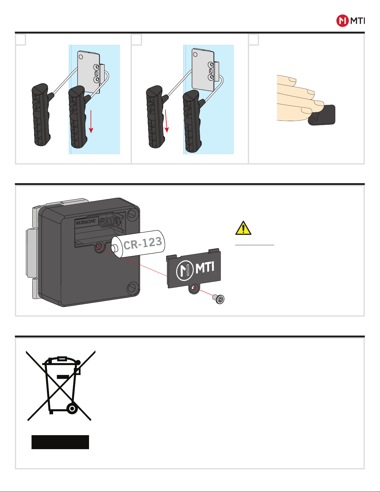
MTI PLUNGER LOCKS™ PRODUCT MANUAL
FCC STATEMENT
FCC ID: 2AA2X-15ØØØ11824
Model: Plunger Lock
FCC STATEMENT
This device complies with Part 15 of the FCC Rules.
Caution: If any changes or modifications not expressly approved by the party responsible for compliance could void the user’s
authority to operate the equipment.
Operation is subject to the following two conditions: (1) This device may not cause harmful interference, and (2) This device
must accept any interference received, including interference that may cause undesired operation.
The grantee is not responsible for any changes or modifications not expressly approved by the party responsible for
compliance. Such modifications could void the user’s authority to operate the equipment.
The RF Exposure Compliance distance is 20 millimeters.
NOTE: This equipment has been tested and found to comply with the limits for a Class B digital device, pursuant to part 15
of the FCC Rules. These limits are designed to provide reasonable protection against harmful interference in a residential
installation. This equipment generates, uses and can radiate radio frequency energy and, if not installed and used in
accordance with the instructions, may cause harmful interference to radio communications. However, there is no guarantee
that interference will not occur in a particular installation. If this equipment does cause harmful interference to radio or
television reception, which can be determined by turning the equipment off and on, the user is encouraged to try to correct
the interference by one or more of the following measures:
- Reorient or relocate the receiving antenna.
- Increase the separation between the equipment and receiver.
- Connect the equipment into an outlet on a circuit different from that to which the receiver is connected.
- Consult the dealer or an experienced radio/TV technician for help.
ISED Certification Number: 24439-15ØØØ11824
Model: Plunger Lock
ISED Statement
This device complies with Innovation, Science and Economic Development Canada licence-exempt RSS standard(s).
Operation is subject to the following two conditions: (1) this device may not cause interference, and (2) this device must
accept any interference, including interference that may cause undesired operation of the device.
CAN ICES-3(B)/NMB-3(B)
Le présent appareil est conforme aux CNR Innovation, Sciences et Développement économique Canada applicables aux
appareils radio exempts de licence. L’exploitation est autorisée aux deux conditions suivantes:
(1) il ne doit pas produire de brouillage et (2) l’ utilisateur du dispositif doit étre prêt à accepter tout brouillage radioélectrique
reçu, même si ce brouillage est susceptible de compromettre le fomctionnement du dispositif.
CAN ICES-3(B)/NMB-3(B)
The device meets the exemption from the routine evaluation limits in section 2.5 of RSS 102 and compliance with RSS-102
RF exposure, users can obtain Canadian information on RF exposure and compliance.
Le dispositif rencontre l’exemption des limites courantes d’évaluation dans la section 2.5 de RSS 102 et la conformité à
l’exposition de RSS-102 rf, utilisateurs peut obtenir l’information canadienne sur l’exposition et la conformité de rf.
This transmitter must not be co-located or operating in conjunction with any other antenna or transmitter. This equipment
should be installed and operated with a minimum distance of 20 millimeters between the radiator and your body.
Cet émetteur ne doit pas être Co-placé ou ne fonctionnant en même temps qu’aucune autre antenne ou émetteur. Cet
équipement devrait être installé et actionné avec une distance minimum de 20 millimètres entre le radiateur et votre corps.
Technical Data
Operating frequency 125KHz , 2.4GHz : 2405- 2480MHz
Operating temperature: 0º C to 40º C
Max power : 125KHz <42dBuA/m at 10m, 2.4GHz < 20 dBm