M2 Antenna Systems RC2800PRKX2SU User manual

M2 Antenna Systems, Inc. 4402 N. Selland Ave. Fresno, CA 93722
Tel: (559) 432-8873 Fax: (559) 432-3059 Web: www.m2inc.com
©2016 M2 Antenna Systems Incorporated 04/27/12
Rev.01
M2 Antenna Systems, Inc.
Model No: RC2800PRKX2SU
Advanced Operations
Controller Overview Connections / Start UP Trouble Shooting
SPECIFICATIONS
MODEL NUMBER .................................................... RC2800PRKX2SUMC
POWER REQUIREMENTS...................................... 115 / 230 VAC @ 6.7A / 5.0
ENCLOSURE SIZE .................................................. W=19” / H=5.25” / D=10”
COLOR..................................................................... Clear Anodized / Black & Rear Black Anodized
POINTING ACCURACY........................................... <0.3°
READOUT ACCURACY .......................................... <0.1°
MINIMUM COMMANDED MOTION ........................ >0.25°
DIGIT SIZE............................................................... 0.5” Heading / .375” Mode / Speed
CONTROL SWITCHES.............................................Tactile 0.5” Diameter
MICROPROCESSOR TYPE.....................................“Microchip” PIC18F2520-I/SP
CONTROLS ..............................................................Power Switch, ON / OFF
Speed Buttons, Increments 1-9
Clockwise & Counterclockwise Buttons
Up & Down Mode Buttons
MODES .....................................................................(3) Operational Run Modes / (10) Presets
STANDARD OUTPUT VOLTAGE ............................AZ / EL = 48 VDC 6.7 AMP
COMPUTER INTERFACE ........................................RS232 (X2) or USB (X2)
FEATURES
The M2 RC2800PRKX2SUMC is our Mid Grade rack-mount controller. The RC2800PRKX2SUMC was developed for “Commercial
Grade” AZ/EL Pedestal Models (AE1000, AE1000CB and AE1000CBW)*Also available for a (3) Axis System.
The M2 RC2800PRKX2SUMC uses a Microchip PIC18F2520-I/SP for Micro processing user commands, M2 software and EEprom
for memory. User modes include: (3) Operational / Run Modes and (10) programmable presets.
The M2 RC2800PRKX2SUMC uses a Meanwell switching power supply so 115VAC or 230VAC can be used for the main power
input with no switching needed.
The M2 RC2800PRKX2SUMC uses PWM (Pulse Width Modulation) for speed control, allowing for full torque at the slowest input
speed. Location heading from the motor assembly is supplied via an Open Loop Circuit to the controllers’ microprocessor.
The M2 RC2800PRKX2SUMC software was developed for a commercial customer. A full GUI software for setup and run modes
and a Interface Control Document (ICD) is supplied with the RC2800PRKX2SUMC.
Computer interface to the RC2800PRKX2SU is via (2) individual RS232 ports or as an option (2) USB ports.

ON/OFF (POWER)
This button controls AC power to the control unit.
DIGITAL DISPLAY & DIGITS
#1: (full left) shows the selected MODE for operation or programming.
#2: Indicates the Positioner travel SPEED in relative numbers from 0 to 9.
#3: Indicates an “. Or -” for a limit zone or a digit when programming in a high gear ratio.
#4,5,6,7: Indicates HEADINGS, Azimuth / Elevation / Polarity, in degrees and programming data.
“MODE” BUTTONS
The MODE buttons are used to cycle through and select among (5) operational or RUN modes and 10 PRESETS.
See RUN MODES and PROGRAM MODE details following this section.
“SPEED” BUTTONS
The SPEED buttons control the positioner’s rate of speed in relative increments. “1” is the slowest speed, “9” is
the fastest. The top button increases the speed, the lower button decreases the speed. The lowest speed
available DEFAULTS to “1”, but can be set to any number between “1” and “9” in the supplied M2 Setup Utility
Software. Speeds can be altered for travel in any of the run modes.
“CONTROL” BUTTONS
The “CW” and “CCW” or “UP” or “DOWN” buttons, activate the positioners’ direction in MODE “0”, MODE “1”
and MODE “2”. These buttons are also used for “Auto Cal” and “Initial Cal Heading.”
FRONT PANEL CONTROL OVERVIEW
Digital Display
Power Switch
Speed Buttons
Mode Buttons
Control Buttons

“AC IN”
The supplied (3) prong AC cord plugs into this socket. Connect to a reliable 115 or 230 VAC source. The unit is supplied with
switching power supplies that operate from 86VAC to 240VAC.
“MOTOR PROTECTION FUSE”
This fuse provides electrical protection to the positioner. Replace this fuse with a 125VAC 5A fuse.
“RS232” INTERFACE PORT
This is a standard (9) pin female (DB9) connector for linking to a computer for automated control. Do not use a null modem
cable for this application.
This particular unit, has (2) individual RS232 ports for separate positioner operations.
“TERMINAL STRIP”
The (12) position terminal strip, serves as your multi-conductor cable interface to the positioner unit. The cable supplies pow-
er and data from the positioner. Your ground connection is terminal #12. DISCONNECT THE AC POWER CORD WHEN
CONNECTING CABLE LEADS.
RC2800PRKX2SUMC UNITS WITH HEATER:
If your RC2800PRKX2SUMC control unit has the add on power supply, please see wiring designations on Terminals 6 & 7.
The Heater power supply is powered on at all times. *Note, the heater is thermostatically controlled.
TERMINAL NUMBER FUNCTION SUGGESTED COLOR MINIMUM WIRE GAUGE
#1 MOTOR BLACK 16 AWG
#2 MOTOR WHITE 16 AWG
#3 (NOT USED)
#4 (NOT USED)
#5 (NOT USED)
#6 HEATER (+) LEAD RED (IF SUPPLIED) 16 AWG
#7 HEATER (-) LEAD BLACK (IF SUPPLIED) 16 AWG
#8 (NOT USED)
#9 (NOT USED)
#10 REED SWITCH DC + ORANGE 24 AWG
#11 REED SWITCH RETURN BLUE 24 AWG
#12 CASE GROUND BARE NA
((12) POSITION TERMINAL STRIP ASSIGNMENTS
REAR PANEL OVERVIEW
AC In
Fuse
RS232/USB
1 2 3 4 5 6 7 8 9 10 11 12 1 2 3 4 5 6 7 8 9 10 11 12

RUN MODES:
Modes 0, 1 and 2 are all run modes capable of activating the positioner in both the CCW / DWN and CW / UP
direction.
MODE 0 = MANUAL OPERATION MODE:
Pushing the CCW button activates the positioner in the Counter Clockwise direction, and the Heading count will
go down. Pushing the CW button activates the positioner in the Clockwise direction, and the Heading count will
go up. Pressing the UP button activates a specific positioner in the Upward direction and the Heading count will
go up. Pressing the DWN button activates the positioner in the Downward direction and the Heading count will
go down. The positioner runs while CCW / DWN or CW / UP button is depressed, ramping up from minimum
programmed speed to the maximum (9) and then again ramping down to speed (1). When reversing
direction, there is a 2-3 second delay before the positioner is activated. This delay reduces stress on your
antenna and positioner. *This Mode can also be initiated from the M2 Setup Utility Software. *See the M2
Setup Utility usage page for more details.
NOTE:
Rotation direction, i.e., CCW / DWN or CW / UP is defined as if you are looking down on the positioner /
antenna from above.
MODE 1 = SERVICE / MAINTENANCE MODE:
When the Service / Maintenance Mode is initiated, the controller will not respond to any computer commands.
This allows service or maintenance issues to be addressed without the danger of the service technician being
injured. While in Mode 1, the controller can be commanded with both the CCW/DWN or CW/UP buttons to put
the positioner or positioners’ into a stowed position for service or repair. When service is completed, the control
unit must be placed back into MODE 0 (from controller panel) for computer commands.
MODE 2 = PRESET MODE:
Preset mode is another Service / Maintenance oriented mode. When the Preset Mode is initiated, the controller
will not respond to any computer commands. Again this allows service or maintenance issues to be addressed
without injury. The user can program up to (10) Presets per Axis for use in stowing or rotating the positioner or
positioners’ to a known heading for service or repair. Preset headings are programmed into the controller with
the use of the supplied M2 Setup Utility Software. Once the presets are programmed, the user selects with the
CCW / DWN and CW / UP buttons. Motion is initiated to the displayed preset heading after selecting the preset
and NOT pressing any button for 3 seconds. When service is completed, the control unit must be placed back
into MODE 0 (from controller panel) for computer commands.
USER DEFINED PRESETS
ELEVATION “PRESET” HEADINGS
20
21
22
23
24
25
26
27
28
29
AZIMUTH “PRESET” HEADINGS
20
21
22
23
24
25
26
27
28
29
POLARITY “PRESET” HEADINGS
20
21
22
23
24
25
26
27
28
29
BASIC OPERATIONS / RUN MODE DESCRIPTIONS

MINIMUM COMPUTER REQUIREMENTS AND HARDWARE:
500 MHz Intel Pentium II or equivalent Computer (Preferably a Laptop)
256 MB of RAM / 1MB of Disk Space
Windows 98 / XP / Straight through DB9 RS232 Serial Cable
INSTALLING THE M2 SETUP UTILITY SOFTWARE:
Insert the CD into your CD-ROM drive. Follow the simple onscreen instructions. The software will walk you
through each step of the installation.
Start the M2 Setup Utility by double clicking the desktop Icon. To get familiar with your software take a moment to
look over the utility overview.
M2 SETUP UTILITY OVERVIEW:
Rotator Type: Set Azimuth to either (S--center) or (N
-center), Elevation to either (90°) or (180°).
Pulse Divisor: Sets the divide ratio if needed to
change from the defaults. This will require a cal-
ibration of the system if this is changed.
Set Heading: Used to manually set the heading to
the current known physical location.
Auto Cal: Used to automatically calibrate the
heading by moving the positioner to either the CCW /
DWN or CW / UP limit switch location. Note: During
Auto Cal the positioner WILL bypass the electronic
limit to find either the CCW / DWN or CW / UP limit
switch.
Rotator Location / Port: Selects the COM port to
use for connection to the controller. Press the
CONNECT button to connect.
MOTOR SETTINGS:
Motor Timeout: If the controller does not sense that
the positioner has moved “1” degree in this time, an
Error (E1) will be generated.
Max Speed: The motor will ramp up to this speed
as its maximum. The speed is in 10% increments of PWM at 1.2 KHz.
Min Speed: The motor will start at, and ramp down to this speed. The Min speed MUST be set high enough to
keep the motor running to provide “1” degree motion with the MOTOR TIMEOUT value.
Ramp Time: The amount of time spent in each speed increment as it ramps up and down.
Rev Delay: The number of seconds that the controller will force between a reversal from the front panel.
Current Heading: This display is the result of the Poll command response. The heading values are sent from the
controller along with the Status and ID bytes.
13200
M2 SETUP UTILITY INSTALLATION & OVERVIEW

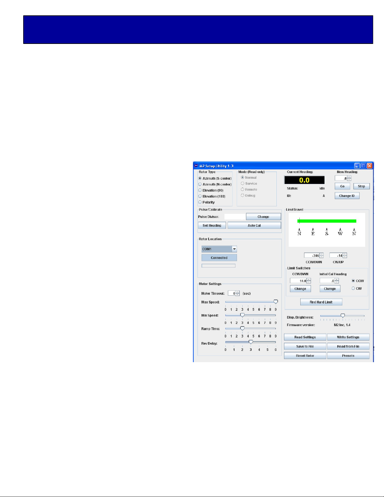
New Heading: Change or type the desired heading
value and click on “Go.” The “Stop” command will
immediately stop the current motion.
Change ID: Changes the ID Byte as stored in the
controller. This can be used to identify a specific
controller board and controller based upon your
usage.
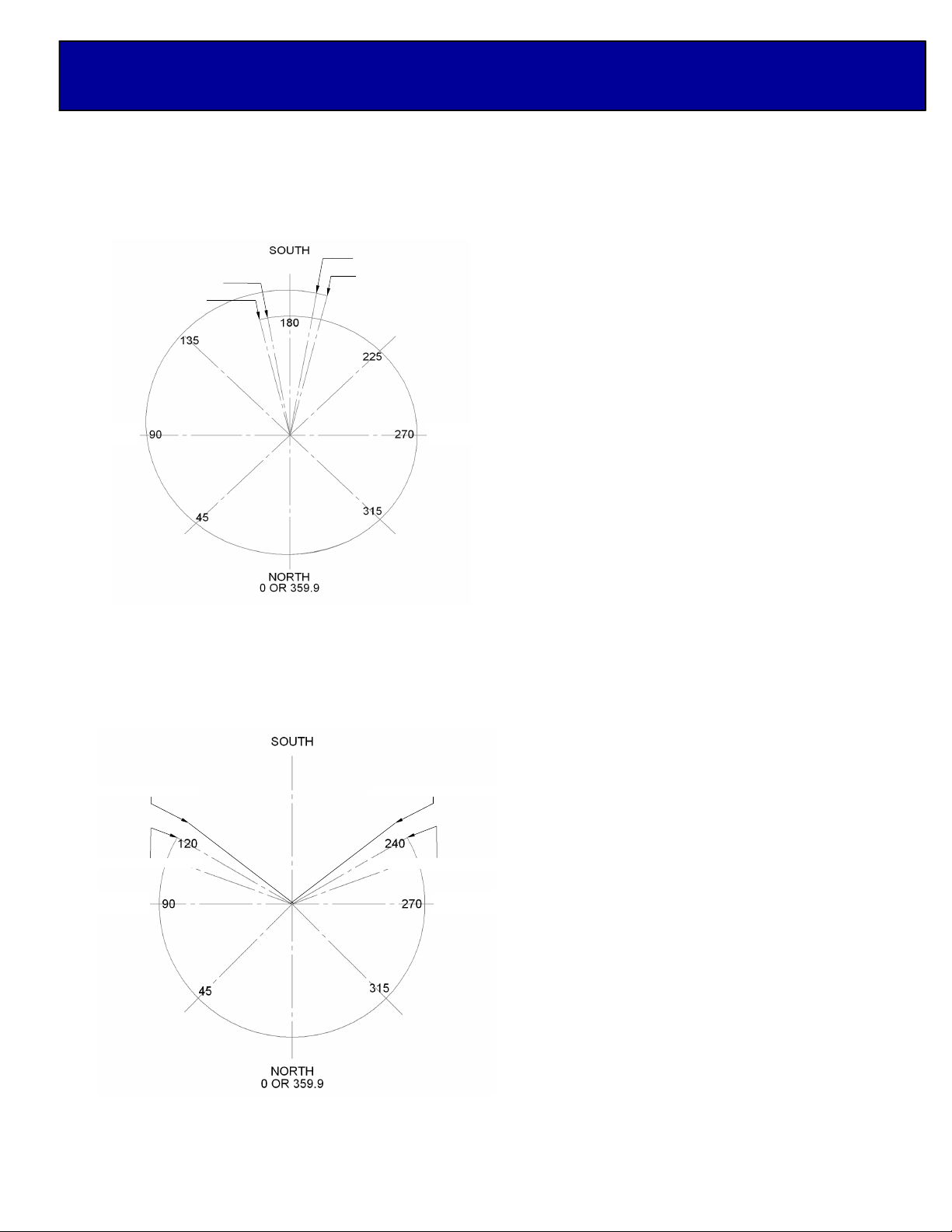
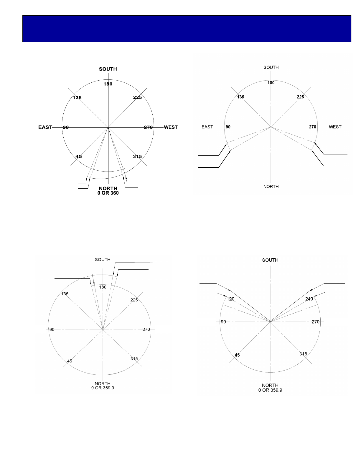
Limit Travel: A graphical representation of allowable
range of the motion as defined by the current po-
sitioner type and the Soft Limits set in the Limit Travel
spinners located just below the graphic.
Limit Switches: CCW / DWN or CW / UP defines
the number of degrees and tenths that the
CCW / DWN or CW / UP limit switch is physically
located from the known start heading.
Initial Cal Heading: This defines the known starting
location in degrees. Normally a fixed location within
your standard travel pattern.
Find Hard Limit: Once the determined hard limit is
chosen, whether it be CCW / DWN or CW / UP,
pressing the Find Hard Limit will run the positioner at
the slowest speed until it trips the limit switch.
The measured CCW / DWN or CW / UP limit switch
value will then be saved in the controller for use by
the Auto Cal Function.
Display Brightness: Changes the brightness level of the LED Display.
Firmware Version: Displays the current firmware from the controller when connected.
Read Settings: Button that will read the settings from the controller and re-populate the SETUP window.
Write Settings: Writes any changes made to values in the SETUP Utility window that do NOT have their own
“Change Button.” All values are re-read after a Write Settings.
Save to File: Saves the current settings into a file for later recall and writing to a controller. This is a backup
mechanism so that you may save each controller’s settings into separately named files and recall them for later
use should the controller need to be replaced, or otherwise restored.
Read from File: Reads the saved values from the specified file. Use Write Settings after a read in order to
restore the values back into a controller.
Reset from File: Reads the saved values from the specified file. Use Write Settings after a read in order to
restore the values back into a controller.
Presets: Reads the (10) current presets from the controller and displays them for change. You may change only
one preset at a time with the Preset Window.
13200
M2 SETUP UTILITY OVERVIEW CONTINUED...

Each Axis of the RC2800PRKX2SU needs to be configured for a spectrum of use and position of limits. The
programmable limits in the RC2800PRKX2SU control, give the ability to specify the amount of travel around a
spectrum of use. The AZ and EL 2 axis positioner has physical limits CCW / DWN and CW / UP. The limits
provide physical stops for safety due to control box failure. The CCW / DWN or CW / UP limits also create a
reference return for each axis when using the “Auto cal” feature during Remote/computer or manual control.
Below we have provided a visual explanation of some common axis configurations complete with suggested
electrical and physical limits and spectrum of use.
AZIMUTH AXIS OPTION #2
Characteristics
Spectrum of use: 240°
Over travel amount: 20°
SU Designation: Azimuth (S-center)
OVERVIEW:
This azimuth configuration may be used when
less than 360° of travel is necessary with a
southern exposure and avoids limits where most
of the operations are being preformed. Note the
position of the Physical limit switches, they are
on the outside of the electrical limits. Again, this
provides safety when and if a control box fails.
AZIMUTH AXIS OPTION #1
Characteristics: Azimuth (S-Center)
Spectrum of use: + 360°
Over travel amount: 12°
SU Designation: Azimuth (S-center)
OVERVIEW:
This azimuth configuration may be used when
360° of travel is necessary with primarily a
southern exposer and avoids limits where most
of the operations are being preformed. Note the
position of the Physical limit switches, they are
on the outside of the electrical limits. Ultimately,
this provides safety when and if a control box
fails.
CCW ELECTRICAL LIMIT 70°
CCW PHYSICAL LIMIT 60°
CW ELECTRICAL LIMIT 290°
CW PHYSICAL LIMIT 300°
VIEWED FROM THE
TOP OF THE SYSTEM
LOOKING DOWN
AZIMUTH SYSTEM CONFIGURATION
CW PHYSICAL LIMIT –.6°
CW ELECTRICAL LIMIT –.3°
CCW PHYSICAL LIMIT –.357°
CCW ELECTRICAL LIMIT –.349°

AZIMUTH AXIS OPTION #3
Characteristics
Spectrum of use: + 360°
Over travel amount: 12°
SU Designation: Azimuth (N-Center)
OVERVIEW:
This azimuth configuration may be used when
360° of travel is necessary with primarily a
northern exposure and avoids limits where most
of the operations are being preformed. Note the
position of the Physical limit switches, they are
on the outside of the electrical limits. Ultimately,
this provides safety when and if a control box
fails.
AZIMUTH AXIS OPTION #4
Characteristics
Spectrum of use: + 240°
Over travel amount: 10°
SU Designation: Azimuth (N-Center)
OVERVIEW:
This azimuth configuration may be used when
240° of travel is necessary with primarily a
northern exposure and avoids limits where most
of the operations are being preformed. Note the
position of the Physical limit switches, they are
on the outside of the electrical limits. Ultimately,
this provides safety when and if a control box
fails.
EAST WEST
CCW ELECTRICAL LIMIT –.174°
CCW PHYSICAL LIMIT –.177°
CW ELECTRICAL LIMIT –.183°
CW PHYSICAL LIMIT –.186°
VIEWED FROM THE TOP
OF THE SYSTEM
LOOKING DOWN
WEST
CCW PHYSICAL LIMIT 235°
CCW ELECTRICAL LIMIT 240°
EAST
CW PHYSICAL LIMIT 125°
CW ELECTRICAL LIMIT 120°
VIEWED FROM THE TOP
OF THE SYSTEM
LOOKING DOWN
AZIMUTH SYSTEM CONFIGURATION CONTINUED...

ELEVATION AXIS OPTION #1
Characteristics
Spectrum of use: 0° to 90° plus
Over travel amount: 10°
SU Designation: Elevation 90°
OVERVIEW:
This Elevation configuration is used as standard
throughout the industry and may be used when
0° to 90° of travel is necessary. Note the position
of the Physical limit switches, they are on the
outside of the electrical limits. Ultimately this
provides safety when and if a control box may
fail.
VIEWED FROM THE
SIDE OF THE
SYSTEM
UP PHYSICAL LIMIT .105°
DWN ELECTRICAL LIMIT –.5°
DWN PHYSICAL LIMIT –.10°
UP ELECTRICAL LIMIT .100°
ELEVATION AXIS OPTION #1
Characteristics
Spectrum of use: 0° to 180° plus
Over travel amount: 10°
SU Designation: Elevation 180°
OVERVIEW:
This Elevation configuration is used as standard
throughout the industry and may be used when
0° to 180° of travel is necessary. Note the
position of the Physical limit switches, they are
on the outside of the electrical limits. Ultimately
this provides safety when and if a control box
may fail.
*Note due to your dish or antenna size, there
may be limitations of the overall range above
125°.
HORIZON HORIZON
DWN ELECTRICAL LIMIT –.5°
DWN PHYSICAL LIMIT –.10°
VIEWED FROM THE
SIDE OF THE
SYSTEM
UP ELECTRICAL LIMIT .180°
UP PHYSICAL LIMIT .185°
ELEVATION SYSTEM CONFIGURATION

AZIMUTH OPTION #1
AZIMUTH (S-Center)
AZIMUTH OPTION #2
AZIMUTH (S-Center)
NOTES___________________________________________________________________________________
_________________________________________________________________________________________
_________________________________________________________________________________________
_________________________________________________________________________________________
_________________________________________________________________________________________
_________________________________________________________________________________________
__
WESTEAST
EAST WEST
AZIMUTH OPTION #3
AZIMUTH (N-Center) AZIMUTH OPTION #4
AZIMUTH (N-Center)
NOTES___________________________________________________________________________________
_________________________________________________________________________________________
_________________________________________________________________________________________
_________________________________________________________________________________________
_________________________________________________________________________________________
_________________________________________________________________________________________
__
AZIMUTH AXIS CONFIGURATION WORK SHEET

NOTES___________________________________________________________________________________
_________________________________________________________________________________________
_________________________________________________________________________________________
_________________________________________________________________________________________
_________________________________________________________________________________________
_________________________________________________________________________________________
__
HORIZON HORIZON
ELEVATION OPTION #1
ELEVATION (90°)
ELEVATION OPTION #2
ELEVATION (180°)
ELEVATION AXIS CONFIGURATION WORK

SPEEDS AND RAMP OVERVIEW:
Depending upon your particular system needs, you may find it necessary to adjust minimum to maximum speeds
and ramp time durations.
EXAMPLE # 1:
If your system is a very large Dish or Phased Array with a lot of weight, wind
area and inertia, it may be necessary to increase your maximum ramp up
and ramp down duration. This can be adjusted by using the “Ramp Time”
slide bar in the setup utility. The “Ramp Time” is the amount of time spent in
each speed increment as it ramps up and down. It may also be suggested
that your maximum speed be lowered to (5) or (6). This can be adjusted by
using the “Max Speed” slide bar in the setup utility. The “Max Speed” is the
maximum speed achieved during rotation. The suggested minimum speed
for a very large array would be (3). You can adjust this by using the “Min
Speed” slide bar in the setup utility. The “Min Speed” is the minimum
starting speed. However, please keep in mind, The “Min Speed” must be set
high enough to keep the motor running to provide at least “1” degree motion
with the “Motor Timeout” value.
EXAMPLE # 2:
A system that has minimal weight and wind area, does not necessarily need
the longer ramp up and ramp down duration. There is not as much starting
and stopping torque on motors and bearings. However, it is always your
choice to setup your axis system based upon your particular needs.
STANDARD FACTORY SETTINGS:
These settings have been pre-programmed at the factory.
Elevation Axis:
Min Speed = 3 Max Speed = 9 Ramp Time = 3 Rev Delay = 3
Azimuth Axis:
Min Speed = 3 Max Speed = 9 Ramp Time = 3 Rev Delay = 3
Please keep in mind, a little experimentation can help you understand each of these settings and how they
interact within each other.
EXAMPLE # 1
EXAMPLE # 2
UNDERSTANDING MIN / MAX SPEEDS & RAMPS

The pictures on this page shows the standard wiring in the junction boxes (with switch reversing diodes) & 5 pin
female right angle connector assembly. The system works the following way: Current is constant through the limit
switches and through to the positioner. When the limit switch is activated, it breaks the contact and stops the cur-
rent from continuing. Reversing the positioner in the opposite direction, incorporates directional diodes. Because
this is a standard wiring system, there may be variations to this system that may be changed by your specific ori-
entation of each Axis.
AZ/EL JUNCTION BOX CONNECTIONS

CONNECTIONS:
Once the Azimuth and Elevation units have been wired up at the motor end, start the process of wiring the correct
color wires to the rear of the control unit. Use the table below for proper wire color and terminal number. Each
individual (12) position terminal strip, has been clearly marked to help with proper connection points.
Unwrap the AC power cord and plug it into the AC plug on the rear of the control unit. Plug the AC cord into a
reliable 115 VAC or 230 VAC source. Switching power supplies are used that can operate from 86VAC to
240VAC.
CUSTOMER NOTE AREA:
CONNECTIONS AND START UP
1 2 3 4 5 6 7 8 9 10 11 12 1 2 3 4 5 6 7 8 9 10 11 12
TERMINAL NUMBER FUNCTION SUGGESTED COLOR MINIMUM WIRE GAUGE
#1 MOTOR BLACK 16 AWG
#2 MOTOR WHITE 16 AWG
#3 (NOT USED)
#4 (NOT USED)
#5 (NOT USED)
#6 HEATER (+) LEAD RED 16 AWG
#7 HEATER (-) LEAD BLACK 16 AWG
#8 (NOT USED)
#9 (NOT USED)
#10 REED SWITCH DC + ORANGE 24 AWG
#11 REED SWITCH RETURN BLUE 24 AWG
#12 CASE GROUND BARE NA
((12) POSITION TERMINAL STRIP ASSIGNMENTS

HEATER UNIT CONNECTIONS
Remove the (8) 8-32 screws from the front limit
switch panel.
1/4” Prepare the provided 2-Conductor Red &
Black 16AWG wire. Remove (5-1/4”) of
the outer grey jacket. Strip (1/4”) of
insulation from both the Red & Black
wires as shown.
Slide the prepared 2-Conductor Red & Black 16AWG wire through the cord grip from the front of
the panel. Route the Red wire to position “A” as shown below. Then route the Black wire to
position “B” as shown below. Tighten small flathead screws on the terminal strip. Place the front
panel onto the LSK enclosure and reinstall the (8) 8-32 screws. Tighten the cord grip nut on the
front of the panel.
5”
A
B

FINAL SETUP OF THE LIMIT SET SCREWS:
We have included (2) limit screws, one for each limit switch. The limit screws can be setup at any position based
upon the orientation of your choice. On Azimuth and Elevation use the supplied 8-32 x 1/2” set screws and 5/64
allen wrench. DO NOT INSTALL AT THIS TIME. You can always make slight adjustments to the limit screw if
necessary. We have provided adjustment holes at every 5°. We suggest leaving the cover off of the unit until you
have completed your testing.
LSK-1000 OVERVIEW:
The LSK-1000 limit switch kit is a physical hard backup limit. The standard control unit supplied with our AZ or EL
has “Electronic Limits”, but the LSK-1000 limit switch kit, has been designed as a physical backup system in
the event of a control unit failure. The factory has pre-installed the LSK-1000 limit switch kit into the AZ and EL
units for you. Typically the LSK-1000 limit switches only need to be setup once, but can be adjusted when
necessary.
LSK-1000 MANUAL LIMIT SWITCH PRE-TEST:
Remove one half of the black enclosure from the
positioner unit that DOES NOT have cord grips or
wires running into it. You will see the limit switches
(A,B) the limit arm (C), and limit screw (D) as pic-
tured to the right. We have not installed the limit
screw due to unknown customer orientation. Move
the supplied RC2800PRKX2SU control unit near the
positioner for proper limit switch testing. With the
positioner wired to the control unit, turn the control unit
on. Be sure to test the proper direction of each
positioner before moving forward. Once you have
determined the correct direction of rotation from the
control units’ “Control Buttons,” determine which limit
switch will be activated by the rotation of the main
gear and limit screw. Press a known direction using
the “Control Buttons,” and manually activate the limit
switch. At this point the positioner should stop it’s
travel. Continue holding the limit switch and reverse
the direction using the “Control Buttons.” The motor
should moved away from the engaged limit switch.
This confirms proper wiring and operation of the limit
switch. Repeat this procedure for the other direction
and limit switch. We suggest, completing each axis
(ie Azimuth and Elevation) prior to moving onto the
final setup.
AZ/ EL-1000 LIMIT SWITCH ARANGEMENT
AZ/EL PHYSICAL LIMIT SWITCH PRE TEST

AZIMUTH SETUP AND CALIBRATION:
1. Connect a straight through DB9 RS232 serial cable to the rear of the RC2800PRKX2SUMC controllers’
“Azimuth” port. Now connect the RS232 serial cable to your laptop or desktop computer being used for setup.
2. Under programs , start the M2 Setup Utility program. Select COM1 in the setup utility under “Rotor Location.”
Click “Connect” and once the azimuth control board has been verified, the word “Connected” will appear.
3. Confirm that the either the Azimuth (N-Center) or Azimuth (S-Center) rotator type is selected and that this is
the same port that the serial cable is plugged into on the rear of the control unit. Then verify that the “Pulse
Divisor” is set to the correct value for Azimuth (13200).
4. Using the CCW / DWN or CW / UP buttons on the front of the controller, rotate the Azimuth unit to a known
fixed heading position. This can be any known heading within your specified limit travel area. Note, the actual
digital display heading may not be the actual physical heading of your Azimuth unit at this time, due to your
orientation. Once you are confident that you are physically pointed at your known heading, click the “Set
Heading” button in the setup utility. Enter in the known heading in degrees and then click OK to calibrate your
heading.
USING YOUR AZIMUTH CONFIGURATION WORKSHEET:
5. Using your Axis configuration worksheet, insert both the CCW and CW electronic limits into the setup utility. To
finish this process, click the “Write Settings” button located at the bottom of the utility. At this time, it would be
good to determine the largest sweep of rotation. This is important as you have the choice of setting up either the
CCW or CW hard limit as your “Auto Cal” location. If most of your travel happens to be closer to the CW hard
limit, choose this in the setup utility. If not, we suggest using the CCW hard limit.
6. Based upon your choice from above, press either the CCW or CW button to rotate the azimuth axis until the
motor stops. This will either be your CCW or CW desired electronic limit.
POSITIONING EITHER THE CCW OR CW PHYSICAL LIMIT SCREW:
7. Visually inspect the physical limit switches and limit arm. Activate the limit arm into the limit switch, noting the
location in which the limit arm contacts the wheel of the limit switch. At this point, insert the supplied 8-32 x 1/2”
limit set screw into the hole just outside of the limit arm. This will give you some room between the CCW or CW
electronic limit and the CCW or CW physical limit. This position is not critical other than to give you a reference
point. The controller will calculate absolute distance automatically.
FIND CCW OR CW PHYSICAL LIMIT:
8. Press the “Find Hard Limit” button on the setup utility to start the automatic calibration process. During this
process, the azimuth axis will rotate in either the CCW or CW direction (based upon your initial setup) until it
touches either the CCW or CW physical limit. Note, the azimuth unit will drive through either the CCW or CW
electronic limit, disregarding it during this process. The control box will then calculate the absolute distance
between these two points. This information will automatically be updated in your CCW/DWN or CW/UP limit
switch location.
At this point, you have now establish your reference return point for this axis. The “Auto Cal” can now be used
from either the setup utility, hyper terminal or your own communication software.
AZIMUTH AXIS SETUP AND CALIBRATION

ELEVATION AXIS SETUP AND CALIBRATION:
1. Move the RS232 serial cable to the Elevation port on the back of the controller. Under “Rotor Location.” Click
“Connect” and once the elevation control board has been verified, the word “Connected” will appear.
2. Confirm that either the Elevation (90) or Elevation (180) rotator type is selected and that this is the same port
that the serial cable is plugged into on the rear of the control unit. Then verify that the “Pulse Divisor” is set to the
correct value for Elevation (13200).
USING YOUR ELEVATION CONFIGURATION WORKSHEET:
3. Using your Axis configuration worksheet, insert both the DWN and UP electronic limits into the setup utility. To
finish this process, click the “Write Settings” button located at the bottom of the utility.
4. At this point, refer to the Azimuth procedures for setup and calibration of your Elevation axis. As both the
Azimuth and Elevation units are very similar regarding setup other than actual degree headings.
ELEVATION AXIS SETUP AND CALIBRATION

CONNECTIONS TO COMPUTER:
Connect the appropriate cable from your computer to the Control Unit’s DB9 connector on the rear panel.
(A standard RS232 cable is sufficient to run the controller. Do not use a null cable.)
All computers have a “Hyper Terminal” or equivalent capability for “Talking” to the control unit. To setup the
“Hyper Terminal” do the following: Click start, programs, accessories, communications and then
“Hyper Terminal.”
The next screen you will see is called “Connection Description.” It will ask you to enter a name (IE. positioner)
and choose an icon, then click OK.
The next screen will read “Connect To.” Scroll to the last box and click on “Connect Using.” Choose direct to
Com 1 (or whatever Com port you have available) and then click OK.
The final screen will have standard Port Settings. Change the port settings to the following and press OK.
Baud Rate Bits Stop Bits Parity Handshake
9600 81None Present, not used
COMPUTER SOFTWARE CLARIFICATIONS:
Commands are one letter or two letter, one number codes followed by a digit. (n)
In many commands, the (n) may be any numeric and must be a “0” (zero) where specified in the Command.
All commands and responses MUST terminate with ; (semi-colon), Commands are in bold for clarity. Parts
enclosed in ( ) are optional.
There are no inter-character timeouts, sending ; alone will:
A. Stop Controller command motion
B. Clear the RX buffer
There are no controller initiated transmissions.
STANDARD USER PROGRAM COMMANDS:
Bin ; = Poll controller for Status / Heading
(Response = “ID_Byte, Status_Byte, Heading;” ID-BYTES=ASCII Char 0-9 or A-Z STATUS_BYTE=)
S = Stopped / Idle
R = Running (motor in motion)
C = Calibration in Process
O = Offline (Controller NOT in MODE 0)
E = Error
Heading in form of (-)xxx.y;
Stn; or ; Stops a computer or preset command.
APn(-)xxx(.y)<cr>; Sends controller to (-)xxx.y degrees if in Mode 0.
C1n; Recalibrate controller at the desired Limit Switch (either CCW/DWN or CW/UP) known location.
ADVANCED OPERATIONS / SOFTWARE COMMANDS

Awn(-)xxx(.Y); Writes new calibration heading.
C0n; (C, Zero,n) = Find Limit Switch (CCW/DWN or CW/UP) from the specified “Initial Cal Heading” and store
limit switch location for subsequent recalibrate commands. Controller MUST NOT be in MODE = 1 (Service)
R1n; Returns Version ID of controller software.
W00; (Zero, Zero) Restores controller to Azimuth Option and all default settings.
PRn; Reads all 10 Preset values from controller.
(Response is #<soh>(-)xxx.y<cr> for 10 locations followed by ;
P#n(-)xxx.y; Writes preset # (0 to 9) into controller memory.
RXn; Reads EE stored value for X
(Response is X<soh>yyy;
WXnyyy; Writes EE value yyy into X location.
The EE locations for X
A = Limit Switch (Tenths of degrees from “Initial Cal Heading” that trips desired limit switch
B = Initial Cal Heading (Heading to use as Limit Switch reference)
AZ-S = 0.0 to 360.0
AZ-N = 180 to 179.9 (one more tenth CW is “-180”)
EL = 0.0 to 90.0
EL = 0.0 to 180.0
E = Reversal Delay in Seconds
F = Minimum Speed (1 to 10)
G = Maximum Speed (1 to 10)
H = CCW / DWN Soft Limit (Heading)
I = CW / UP Soft Limit (Heading)
J = Option:
0 Azimuth S Center
1 Elevation 90
3 Azimuth N Center
4 Elevation 180
K = Pulse Divider (0 to 50,000)
L = Limit Switch to use (for calibration) (0=CW, 1=CCW)
M = Mode (Read Only)
0 Normal
1 Service
2 Presets
3 Auto Cal
4 Find Limit
N = Ramp (0 to 9)
O = Brightness (0 to 9)
P = No Motion Timeout in Seconds
R = ID Byte
ADVANCED OPERATION / SOFTWARE COMMANDS
Table of contents
Popular Control Panel manuals by other brands

LinkAYL
LinkAYL LK-CP63X Series quick start guide

Controls
Controls MVP-A6307 product manual

Telefire
Telefire ADR-7000 Technical manual

Balboa Water Group
Balboa Water Group TP500 user guide

Digital Monitoring Products
Digital Monitoring Products XR500 Series Programming guide

Zonefirst
Zonefirst BPE Installation and operating instructions