RUD VWBG-V Firmware update

1
VWBG-V in pink
RUD Ketten
Rieger & Dietz GmbH u. Co. KG
73428 Aalen
Tel. +49 7361 504-1370
Fax +49 7361 504-1171
www.rud.com
RUD-Art.-Nr.: 8503854-EN / 02.015
Hoist ring for bolting
> VWBG-V <
in pink
Safety instructions
This safety instruction/declaration has to be kept on le
for the whole lifetime of the product.
Translation of the original safety instruction
EN
Hoist ring for bolting
Vario (variable bolt lengths)
VWBG-V
EG-Konformitätserklärung
entsprechend der EG-Maschinenrichtlinie 2006/42/EG, Anhang II A und ihren Änderungen
Hersteller:
RUD Ketten
Rieger & Dietz GmbH u. Co. KG
Friedensinsel
73432 Aalen
Hiermit erklären wir, dass die nachfolgend bezeichnete Maschine aufgrund ihrer Konzipie-
rung und Bauart, sowie in der von uns in Verkehr gebrachten Ausführung, den grundle-
genden Sicherheits- und Gesundheitsanforderungen der EG-Maschinenrichtlinie
2006/42/EG sowie den unten aufgeführten harmonisierten und nationalen Normen sowie
technischen Spezifikationen entspricht.
Bei einer nicht mit uns abgestimmten Änderung der Maschine verliert diese Erklärung ihre
Gültigkeit.
Produktbezeichnung: Wirbelbock
_____________________________________________
VWBG-V / VWBG
_____________________________________________
Folgende harmonisierten Normen wurden angewandt:
EN 12100 : 2011-03 EN 1677-1 : 2009-03
_________________ _________________
EN 1677-4 : 2009-03
_________________ _________________
_________________ _________________
_________________ _________________
_________________ _________________
Folgende nationalen Normen und technische Spezifikationen wurden außerdem angewandt:
BGR 500, KAP2.8 : 2008-04
_________________ _________________
_________________ _________________
_________________ _________________
_________________ _________________
_________________ _________________
Für die Zusammenstellung der Konformitätsdokumentation bevollmächtigte Person:
Reinhard Smetz, RUD Ketten, 73432 Aalen
Aalen, den 27.06.2014
Dr.-Ing. Arne Kriegsmann,(Prokurist/QMB)
_____________________________________________
Name, Funktion und Unterschrift Verantwortlicher
EC-Declaration of conformity
According to the EC-Machinery Directive 2006/42/EC, annex II A and amendments
Manufacturer:
RUD Ketten
Rieger & Dietz GmbH u. Co. KG
Friedensinsel
73432 Aalen
We hereby declare that the equipment sold by us because of its design and construction,
as mentioned below, corresponds to the appropriate, basic requirements of safety and
health of the corresponding EC-Machinery Directive 2006/42/EC as well as to the below
mentioned harmonized and national norms as well as technical specifications.
In case of any modification of the equipment, not being agreed upon with us, this declara-
tion becomes invalid.
Product name:
Load ring
_____________________________________________
VWBG-V / VWBG
_____________________________________________
The following harmonized norms were applied:
EN 12100 : 2011-03 EN 1677-1 : 2009-03
_________________ _________________
EN 1677-4 : 2009-03
_________________ _________________
_________________ _________________
_________________ _________________
_________________ _________________
The following national norms and technical specifications were applied:
BGR 500, KAP2.8 : 2008-04
_________________ _________________
_________________ _________________
_________________ _________________
_________________ _________________
_________________ _________________
Authorized person for the configuration of the declaration documents:
Reinhard Smetz, RUD Ketten, 73432 Aalen
Aalen, den 27.06.2014
Dr.-Ing. Arne Kriegsmann,(Prokurist/QMB)
_____________________________________________
Name, function and signature of the responsible person

2VWBG-V in pink
Before initial usage of the RUD VWBG-V
hoist rings please read carefully the safety
instructions. Make sure that you have un-
derstood all subjected matters.
Non-observance can lead to serious per-
sonal injuries and material damage and
eliminates warranty.
1 Safety instructions
ATTENTION
Wrong assembled or damaged lifting points
as well as improper use can lead to injuries
of persons and damage of objects when
load drops.
Please inspect all lifting points before each
use.
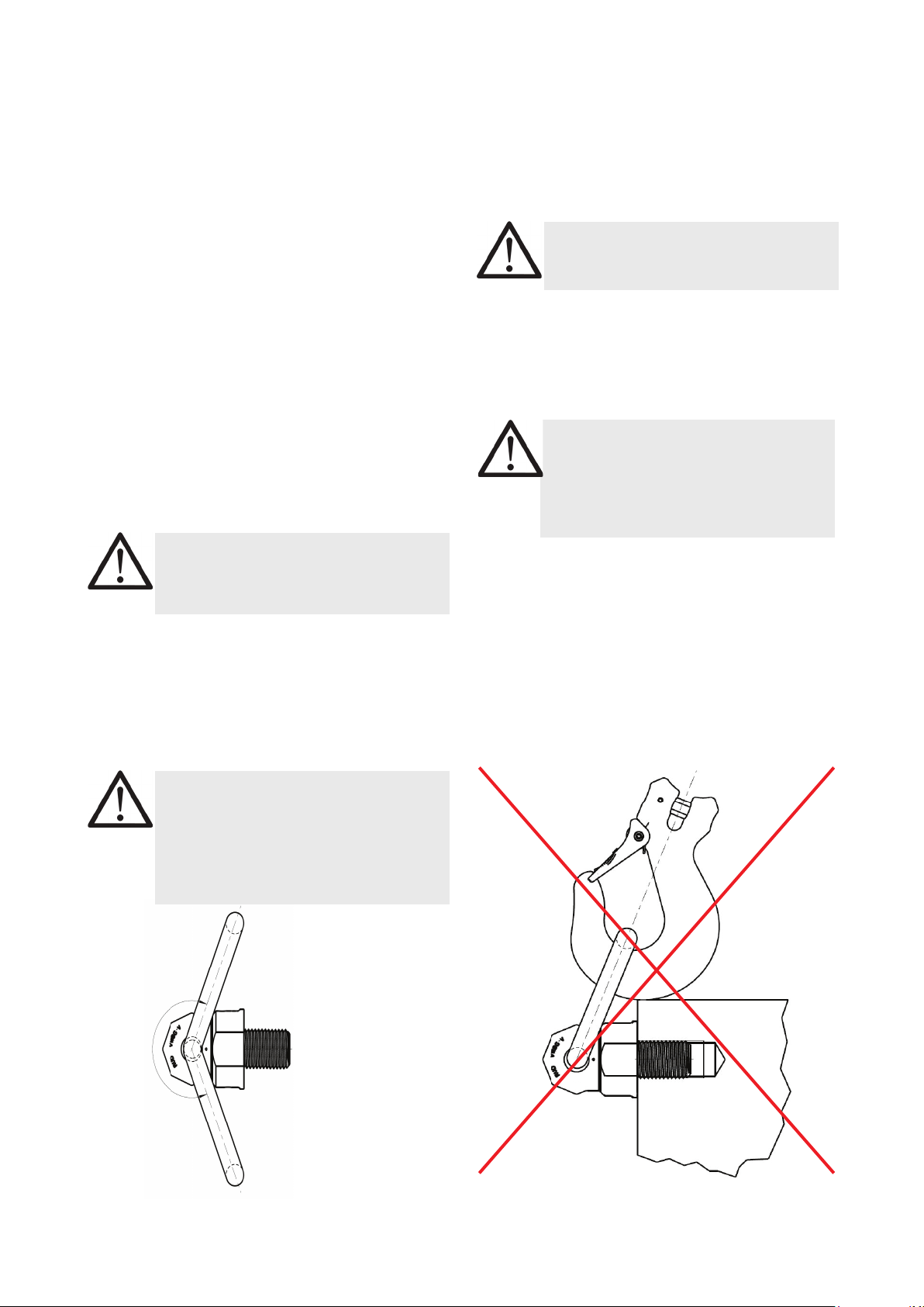
• Not suitable for permanent turning operations un-
der load. Lifting point cannot be turned 90° to the
bolt-on direction under full load.
• The ball bearing resp. the bush bearing disc must
not be disassembled.
• The load ring must not be bend.
• RUD VWBG-V lifting points must only be used by
instructed and competent persons considering
BGR 500 / DGUV 100-500 and outside Germany
noticing the country specic statutory regulations.
2 Intended use of VWBG-V
RUD VWBG-V lifting points must only be used for the
assembly at the load or at lifting means.
They are intended to be hinged into lifting means
and can be turned under load, but not under full load,
especially not in the 90° direction. Not suitable for
permanent turning operations under load.
RUD VWBG-V lifting points can also be used as las-
hing points to attach lashing means.
RUD VWGB-V lifting points must only be used in the
hereby described operation purpose.
3 Assembly- and instruction manual
3.1 General information
• Capability of temperature usage:
Usage at higher temperatures is not recommended
due to the grease lling in the ball bearing. Should
this though be necessary, the working load limit
(WLL) of the VWBG-V must be reduced as follows:
-40°C up to 100°C no reduction
100°C up to 200°C minus 15 %
200°C up to 250°C minus 20 %
250°C up to 350°C minus 25 %
Temperatures exceeding 350°C are prohibited!
Please pay attention when using DIN EN 7042
(DIN 980) nuts the max. operation temperature
of 150°C (acc. to DIN EN ISO 2320).
• RUD VWBG-V lifting points must not be used with
aggressive chemicals such as acids, alkaline so-
lutions and their vapours.
• Please mark mounting position of lifting point with
a coloured contrast paint for better visibility.
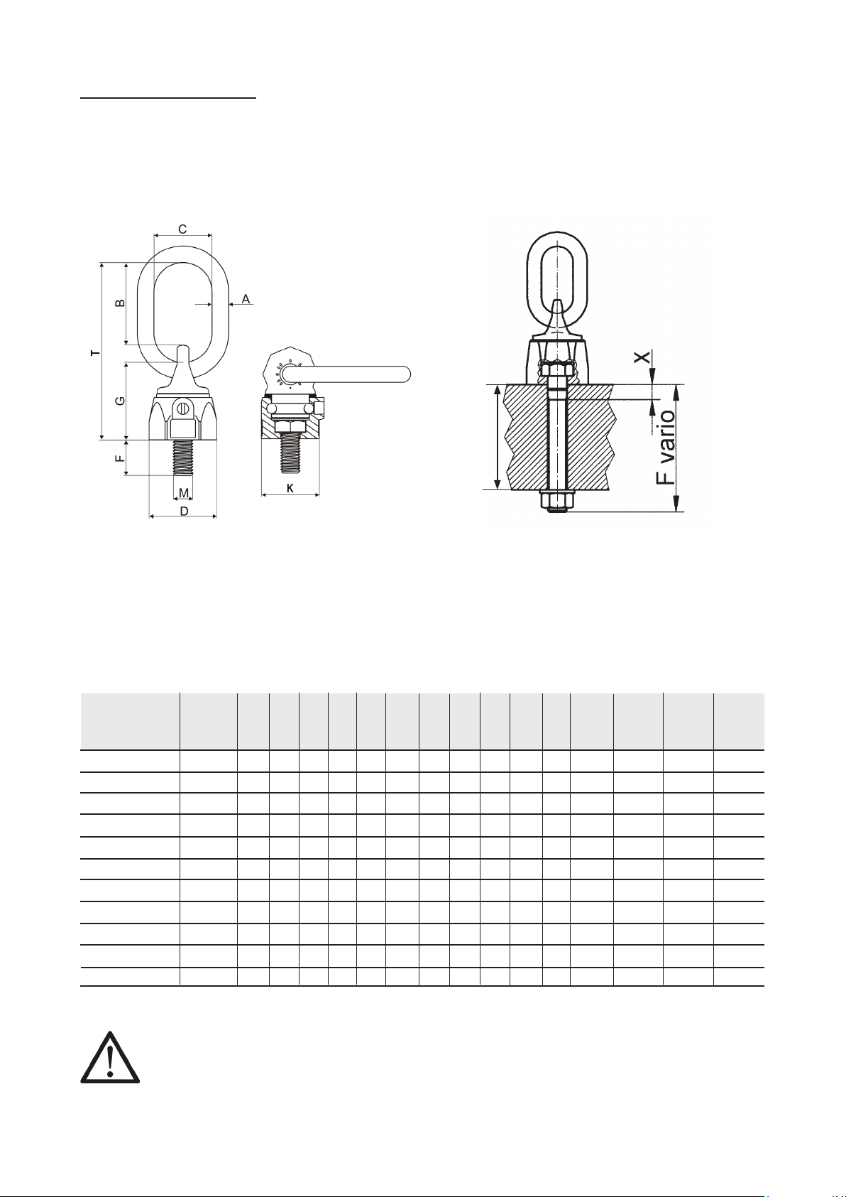
3.2 Hints for the assembly
Basically essential:
• The material construction to which the lifting point
will be attached should be of adequate strength to
withstand forces during lifting without deformation.
The German testing authority BG, recommends
the following minimum for the bolt lengths:
1 x M (thread diameter) in steel
(min. quality 235JR [1.0037])
1,25 x M (thread diameter) in cast iron
(e.g. GG 25)
2 x M (thread diameter) in aluminium
2,5 x M (thread diameter)
in light alloys of low strength
(M = thread size/diameter, e.g. M20)
• When lifting light metals, nonferrous metals and
gray cast iron the thread has to be chosen in such
a way that the WLL of the thread corresponds to
the requirements of the base material.
• The position of the lifting points must be carried
out in such a way that unintended movement like
turning or ipping will be avoided.
• For single leg lifts, the lifting point should
be vertically above the centre of gravity of
the load.
• For two leg lifts, the lifting points must be
equidistant to/or above the centre of gravity
of the load.
• For three and four leg lifts, the lifting points
should be arranged symmetrical around
the centre of gravity, in the same plane if
possible.
• Load symmetry:
Determine the necessary WLL of each lifting point
for a symmetrical or an unsymmetrical load by
using the following physical calculation formula:
Number of load bearing strands:
Symmetric Unsymmetric
two leg 2 1
three / four leg 3 1
Chart 1: Load bearing strands
WLL = necessary WLL of lifting point / single strand
G = weight of load
n = number of load bearing strands
ß = inclination angle of single strand
WLL=G
n x cos ß

3
VWBG-V in pink
• VWBG-Vs are suitable for turning and ipping of
loads. In doing so, all positions of the ring can
occur. The stated WLL at the lifting point is given
for the most inappropriate possible case of opera-
tion (see picture 5 – part X). When ring has been
adjusted manually (see part Y) the higher (WLL)
values from chart 3 can be used
ATTENTION
Pay attention during the usage that the
load type will not be change
If the VWBG-V is will be loaded only perpendicular
(in axial direction of the thread, see picture 3 - part
Z) the corresponding WLL values from chart 3
(inclination angle 0°) can be used.
• The ring of the manually adjusted VWBG-V can
be pivoted by approx. 230° (see picture 1).
ATTENTION
The suspension ring resp. the attached
lifting mean must rotate and pivot without
interference during lifting and must neither
have support at the load edge nor at the
bottom part of the VWBG-V (see picture 2).
• When lifting means (sling chains) are hinged or
unhinged, no pinching, shearing or joint spots must
occure during the handling. Avoid damage of lifting
means resulting from sharp edges.
• Leave direct danger zone as far as possible.
• Watch always your hinged loads.
Picture 1: Pivoting area Picture 2: Forbidden contact or support at/or with
edge
ca. 230°
• A plane bolt-on surface (with a minimum ØD) with
a perpendicular thread hole must be guaranteed.
The thread must be carried out acc. to DIN 76
(countersink max. 1.05xd).
• Tapped holes must be machined deep enough so
that the bearing surface of the lifting point will be
supported. Machine through holes up to DIN EN
20273-middle.
• Due to the ball bearing and the bush bea-
ring it is sufficient for a single lift to tighten
the VWBG-V until the bearing surface has
support by using a spanner acc. to DIN 895
resp. DIN 894, without using an extension.
If the VWBG-V shall permanently installed at the
load, tensioning must be carried out with a torque
(+/- 10 %) according to chart 2.
• The type VWBG-V can be supplied with different
thread lengths (see Fvario in chart 2), and the
metric versions with washer und crack detected
nut.
The assembly resp. the installation of bolts with
different thread lengths is only allowed, if camed
out by either RUD or an authorized RUD distributor.
ATTENTION
Disassembly of the ball bearing resp. the
bush bearing disc carried out by the user
is forbidden.
• Check nally the correct assembly (see chapter 4,
Inspection criteria).
3.3 User instructions
• Check frequently and before each operation the
whole lifting mean in regard of linger ability as a
lifting mean, regarding corrosion, wear, deforma-
tion etc. (see chapter 4, Inspection criteria).
ATTENTION
Wrong assembled or damaged lifting
means as well as improper use can lead to
injuries of persons and damage of objects
when load falls.
Please inspect all lifting points before
each use.

4VWBG-V in pink
4 Inspection criteria
Observe and control the following points before each
initial operation, in regular time intervals, after the
assembly and after special incidents:
• Correct bolt- and nut size plus thread engagement
• Solid bolt xture - Inspection of bolting torque
• The bearing surface of the VWBG-V must lay plane
and holohedral on the bolting area.
• Completeness of the lifting point
• Complete, readable WLL statements as well as
manufacturer sign.
• Deformation at load bearing components like base
body, suspension ring and threaded pin.
• Mechanical damage, like strong notches, especially
in areas where tensile stress occurs.
• Locking screw at the side must be tightened
• Reduction of cross section caused by wear
> 10 %, or when the wear lenses have been rea-
ched in the main load bearing directions
• cracks or any other damage
• Function and damage of bolt threads and nuts
• Easy turning without jerk between upper and base
part of the VWBG-V must be guaranteed.
• The maximum gap between upper and base part
must not be exceeded:
- VWBG-V 0.3 - 0.45: max. 1.2 mm
- VWBG-V 0.6 - 2.0: max. 1.5 mm
- VWBG-V 3.5 - 5.0: max. 3.0 mm
• Avoid impulsive and tiltful loading.
ATTENTION
Impulsive loading or vibration, especially
at through hole connections with nuts, can
lead to unintentional loosening.
Securing possibilities: liquid thread securing
products f.e. Loctite (read manufacturer´s in-
struction) or form closed bolt securing such as a
crown nut with split pin, lock nut etc. can be used.
Secure in general all lifting points which are
installed permanently, e.g. with glue.
• Please observe for the whole lifting mean the RUD
sling chain safety instruction.
3.4 Hints for regular inspection
Lingering appropriateness of lifting means should
be tested by a competent person, depending on the
operational demands or at least once a year (see
chapter 4 Inspection criteria).
Depending on the operational demands, resulting
from a numerous use, f.e. increased wear or corrosi-
on, could make an earlier inspection necessary which
means in a shorter interval than one year.

5
VWBG-V in pink
Picture 4: Dimensioning VWBG-V
* Hint: Stated WLL for 3-4 strands is only valid when
it is guaranteed that the load is distributed equal to
more than 2 strands. Otherwise the 2 strand values
must be taken (see BGR 500 / DGUV 100-500 chapter
2.8 paragraph 3.5.3).
ATTENTION
Please mind at the use especial-
ly that the method of lifting does
not get changed
Picture 3: Dimensioning VWBG-V (metric)
Chart 2: Dimensioning (metric) Subject to technical alterations
Nomination WLL A B C D Fstand Fmax G K M T X weight Bolting Ref.-No. Ref.-No.
[t] [mm] [mm] [mm] [mm] [mm] [mm] [mm] [mm] [mm] [mm] [kg/pc.] Torque Stand. Vario
[Nm] with washer
and nut
VWBG-V 0.3 M8 0.3 (0.4) 8 31 29 30 13 102 36 28 8 76 18 0.25 10 7103720 8600330
VWBG-V 0.45 M10 0.45 (0.6) 8 31 29 36 17 122 38 30 10 78 19 0.3 10 7103715 8600331
VWBG-V 0.6 M12 0.6 (0.7) 10 49 35 42 21 140 47 36 12 107 19 0.4 10 7100180 8600332
VWBG-V 1.0 M14 1.0 (1.25) 13 46 38 48 21 65 56 41 14 113 - 0.6 25 - 8600337
VWBG-V 1.3 M16 1.3 (1.5) 13 46 38 48 25 180 56 41 16 113 28 0.6 30 7100430 8600333
VWBG-V 1.8 M18 1.8 (2.0) 13 54 35 62 27 83 67 55 18 137 - 1.1 50 - 8600338
VWBG-V 2.0 M20 2.0 (2.5) 13 54 35 62 33 223 67 55 20 137 30 1.4 70 7100800 8600334
VWBG-V 2.0 M22 2.0 (2.5) 13 54 35 62 33 94 64 55 22 137 - 1.5 120 - 8600334
VWBG-V 3.5 M24 3.5 (4.0) 18 66 40 81 40 255 88 70 24 173 25 2.6 150 7100640 8600335
VWBG-V 3.5 M27 3.5 (4.0) 18 66 40 81 40 92 88 70 27 173 - 2.9 200 - 8600335
VWBG-V 5.0 M30 5.0 (6.0) 22 90 50 99 50 330 106 85 30 221 32 5.5 225 7100650 8600336
5 Hints for repairing
Repair work must only be carried out by a competent
person at RUD or by a RUD trained and authorized
service station, which has obtained the necessary
knowledge and skills.
RUD-VWBG-Vs are designed for a dynamical loading
of 20.000 load cycles at nominal working load. The
BG recommends: At a high dynamic loading with high
numbers of load cycles (continious work) the bearing
stress acc. to FEM group 1Bm (M3 acc. to DIN 818-7)
must be reduced.
dim. without
thread
= F max
max. material
thickness
Example to investigate the required thread
length Fvario:
Plate thickness 50 mm, through hole for M 20 bolt,
height of nut 20 mm, thickness of the washer 3 mm,
plus bolt projection 5 mm (2x pitch).
Order length: VWBG-V-2.0 M 20 x 78.

6VWBG-V in pink
Chart 3: WLL-overview VWBG-V
methode of lifting
number of strands 1 2 1 2 2 2 2 3 / 4 * 3 / 4 * 3 / 4 *
inclination angle 0° 0° 90 ° 90° 0-45° 45-60° Un- 0-45° 45-60° Un-.
symm. symm
Factor 1 2 1.4 1 1 2.1 1.5 1
Type thread For the max. total load weight >G< in metric tons, tightened and adjusted to force direction.
WBG-V 0,3 M8 / 5/16’’ 0.6 1.2 0.3 (0.4) 0.6 (0.8) 0.42 (0.56) 0.3 (0.4) 0.3 (0.4) 0.63 (0.84) 0.45 (0.6) 0.3 (0.4)
VWBG-V 0,45 M10 / 3/8’’ 0.9 1.8 0.45 (0.6) 0.9 (1.2) 0.63 (0.84) 0.45 (0.6) 0.45 (0.6) 0.94 (1.26) 0.67 (0.9) 0.45 (0.6)
VWBG-V 0,6 M12 / 1/2’’ 1.2 2.4 0.6 (0.75) 1.2 (1.5) 0.84 (1.05) 0.6 (0.75) 0.6 (0.75) 1.26 (1.57) 0.9 (1.12) 0.6 (0.75)
VWBG-V 1.0 M14 2.0 4.0 1.0 (1.25) 2.0 (2.5) 1.4 (1.75) 1.0 (1.25) 1.0 (1.25) 2.1 (2.62) 1.5 (1.87) 1.0 (1.25)
VWBG-V 1.3 M16 / 5/8’’ 2.6 5.2 1.3 (1.5) 2.6 (3.0) 1.81 (2.1) 1.3 (1.5) 1.3 (1.5) 2.73 (3.15) 1.95 (2.25) 1.3 (1.5)
VWBG-V 1.8 M18 3.6 7.2 1.8 (2.0) 3.6 (4.0) 2.52 (2.8) 1.8 (2.0) 1.8 (2.0) 3.78 (4.2) 2.7 (3.0) 1.8 (2.0)
VWBG-V 2.0 M20 / 3/4’’ 4.0 8.0 2.0 (2.5) 4.0 (5.0) 2.8 (3.5) 2.0 (2.5) 2.0 (2.5) 4.2 (5.25) 3.0 (3.75) 2.0 (2.5)
VWBG-V 2.0 M22 4.0 8.0 2.0 (2.5) 4.0 (5.0) 2.8 (3.5) 2.0 (2.5) 2.0 (2.5) 4.2 (5.25) 3.0 (3.75) 2.0 (2.5)
VWBG-V 3.5 M24 / 1’’ 7.0 14.0 3.5 (4.0) 7.0 (8.0) 4.9 (5.6) 3.5 (4.0) 3.5 (4.0) 7.35 (8.4) 5.25 (6.0) 3.5 (4.0)
VWBG-V 3.5 M27 7.0 14.0 3.5 (4.0) 7.0 (8.0) 4.9 (5.6) 3.5 (4.0) 3.5 (4.0) 7.35 (8.4) 5.25 (6.0) 3.5 (4.0)
VWBG-V 5.0 M30 / 11/4’’ 10.0 20.0 5.0 (6.0) 10.0 (12.0) 7.0 (8.4) 5.0 (6.0) 5.0 (6.0) 10.5 (12.6) 7.5 (9.0) 5.0 (6.0)
Chart 4: Dimensioning VWBG-V Subject to technical alterations
Nomination WLL A B C D F G K M T weight Bolting- Ref.-No.
[t] [mm] [mm] [mm] [mm] [mm] [mm] [mm] [mm] [mm] [kg/pc] torque Stand.
[Nm]
VWBG-V 0.3 - 5/16’’ - 18 UNC 0.3 (0.4) 8 31 29 30 13 36 28 5/16’’ 76 0.25 10 7991090
VWBG-V 0.45 - 3/8’’ - 16 UNC 0.45 (0.6) 8 31 29 36 17 38 30 3/8’’ 78 0.3 10 7991091
VWBG-V 0.6 - 1/2’’ - 13 UNC 0.6 (0.7) 10 49 35 42 21 47 36 1/2’’ 107 0.4 10 7991092
VWBG-V 1.3 - 5/8’’ - 11 UNC 1.3 (1.5) 13 46 38 48 29 56 41 5/8’’ 114 0.6 30 7991093
VWBG-V 2.0 - 3/4’’ - 10 UNC 2.0 (2.5) 13 54 35 62 29 67 55 3/4’’ 137 1.4 70 7991094
VWBG-V 3.5 - 1’’ - 8 UNC 3.5 (4.0) 18 66 40 81 40 88 70 1’’ 173 2.6 150 7991095
VWBG-V 5.0 - 11/4’’ - 7 UNC 5.0 (6.0) 22 90 50 99 48 106 85 11/4’’ 221 5.5 225 7991096
Picture 5: Loading directions
* X Y Z
Nominal WLL
(worst case scenario)
manual adjustment
(higher values in brackets pos-
sible depending on usage)
vertical loading
(WLL acc. to chart)
This manual suits for next models
1
Table of contents
Other RUD Safety Equipment manuals