mabe MKR62GWTWB User manual

Service Engineering
- 1
-
Service Manual
March 2017
DRYER KRAKEN
MKR62GWTWB
MKR62FWTWB
XKR72GWTWB
XKR72FWTWB

Service Engineering
- 2
-
INDEX
IMPORTANT SAFETY NOTICE………………………………………………………………..………..3
INTRODUCTION…………………………………………………………………………………………..5
NOMENCLATURE………………………………………………………………………………………...6
MODELS AND ATTRIBUTES..…………………………………………………………………………..7
INSTALLATION INSTRUCTIONS………………………………………………………………………..9
REVERSING THE DOOR……………………..……………………………...………………………....15
TECHNICAL SPECIFICATIONS..………………………………………………………………………18
DEASSEMBLY AND FUNCTIONALITY………………………………………………………………..19
Fallas comunes y soluciones …………………………………………………………………………...25
ELECTRIC DRYER DIAGRAM………………………………………………………………………….28

Service Engineering
- 3
-
IMPORTANT SAFETY NOTICE
The information in this presentation is intended for use by individuals possessing adequate backgrounds of
electrical, electronic, & mechanical experience. Any attempt to repair a major appliance may result in personal
injury & property damage. The manufacturer or seller cannot be responsible for the interpretation of this
information, nor can it assume any liability in connection with its use.
WARNING
To avoid personal injury, disconnect power before servicing this product. If electrical power is required
for diagnosis or test purposes, disconnect the power immediately after performing the necessary checks.
RECONNECT ALL GROUNDING DEVICES
If grounding wires, screws, straps, clips, nuts or washers used to complete a path to ground are removed for
service, they must be returned to their original position & properly fastened.
PERSONAL PROTECTION EQUIPMENT (PPE) TO INSPECT AND REPAIR THE DRYER
Plano Type Safety Glasses.
Antistatic Steel Toe Work Boot.
Cut Resistant Glove(s).
Cut Resistant Sleeve(s).

Service Engineering
- 4
-
CAUTION
Prior to disassembly of the Dryer to access components,
Mabe authorized Service Technicians are REQUIRED to
follow the Lockout / Tagout (LOTO) 6 Step Process
Step 1
Plan and Prepare
Step 4
Apply LOTO device & Lock
Step 2
Shut down the appliance
Step 5
Control (discharge) stored
energy
Step 3
Isolate the appliance
Step 6
“Try It” Verify that the
appliance is locked out

Service Engineering
- 5
-
INTRODUCTION
The Dryer Kraken platform replaces the previous versions of mabe dryers with a new style that combines with
washers Kraken and includes special voltages for specific countries.
Dryer Kraken offers energy saving due use less energy to generate heat and save gas.
A new design of the lint trap filter to retain the lint that the garment gives off.
In some electric models calculates the dry time necessary to save energy.

Service Engineering
- 6
-
NOMENCLATURE
Nomenclature:
At the back of the dryer on the rear panel is the model and serial number of the dryer.
With the next nomenclature:
0516SS50001
Serial Number Description
Month
(MM)
Year
(YY) Dryer Constant. Consecutive number assigned by
the manufacturer site.
05 16 SS 50001

Service Engineering
- 7
-
MODELS AND ATTRIBUTES
Main improvements:
• New backsplash that match with Kraken washers.
MKR62GWTWB
MKR62FWTWB
XKR72GWTWB
XKR72FWTWB
• New knobs that goes with the design of Kraken washers.
• New metallic cover that combines with the Kraken washer.
• New handle integrated at the door.

Service Engineering
- 8
-
• New lint filter design.
• Some models include a LED light to illuminate the interior of the dryer.
• The drum has an organic cover, resistant to corrosion, that reflects the heat faster and allows save
energy per each dry cycle.

Service Engineering
- 9
-
I
NSTALLATION INSTRUCTIONS
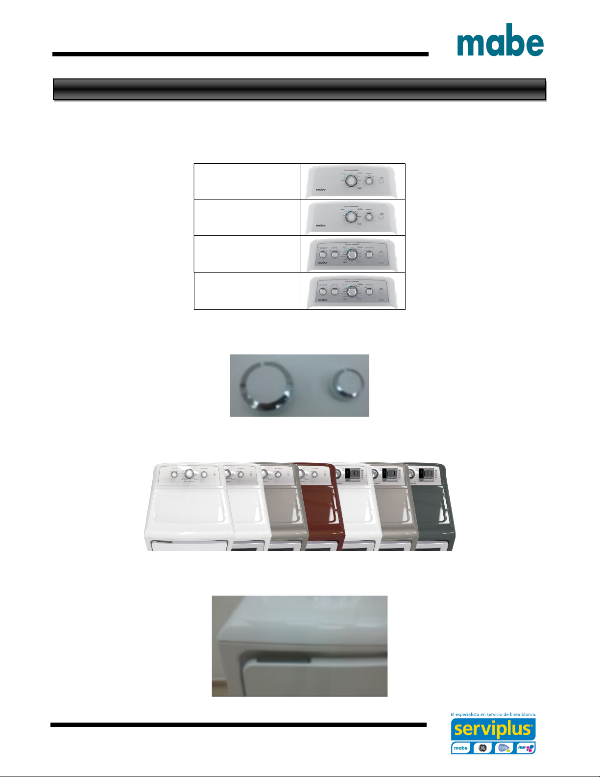
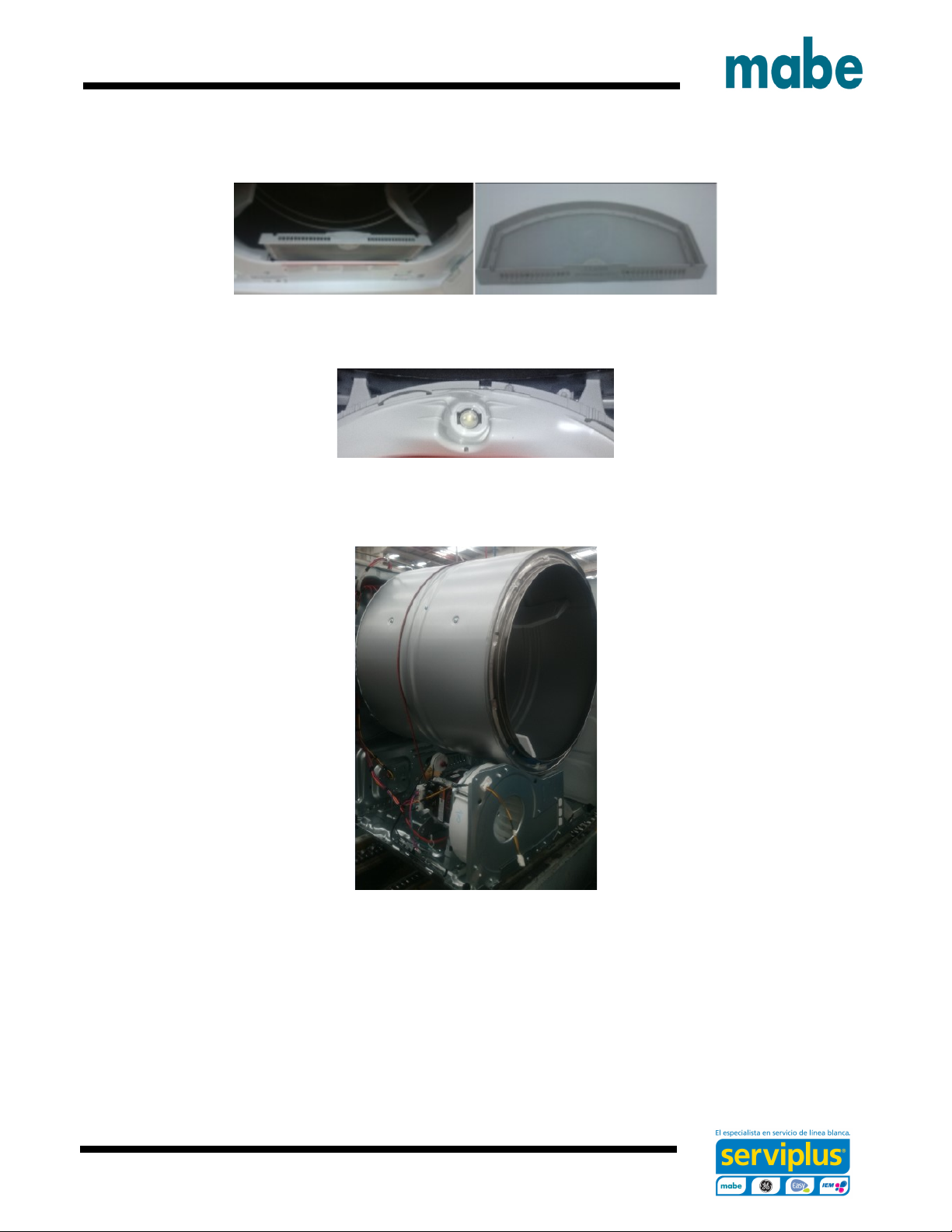
Unpacking your dryer
• Tilt the dryer sideways and remove the foam shipping pads by pulling at the
sides and breaking them away from the dryer legs. Be sure to remove all of
the foam pieces around the legs. Remove literature and bag containing
accessories.
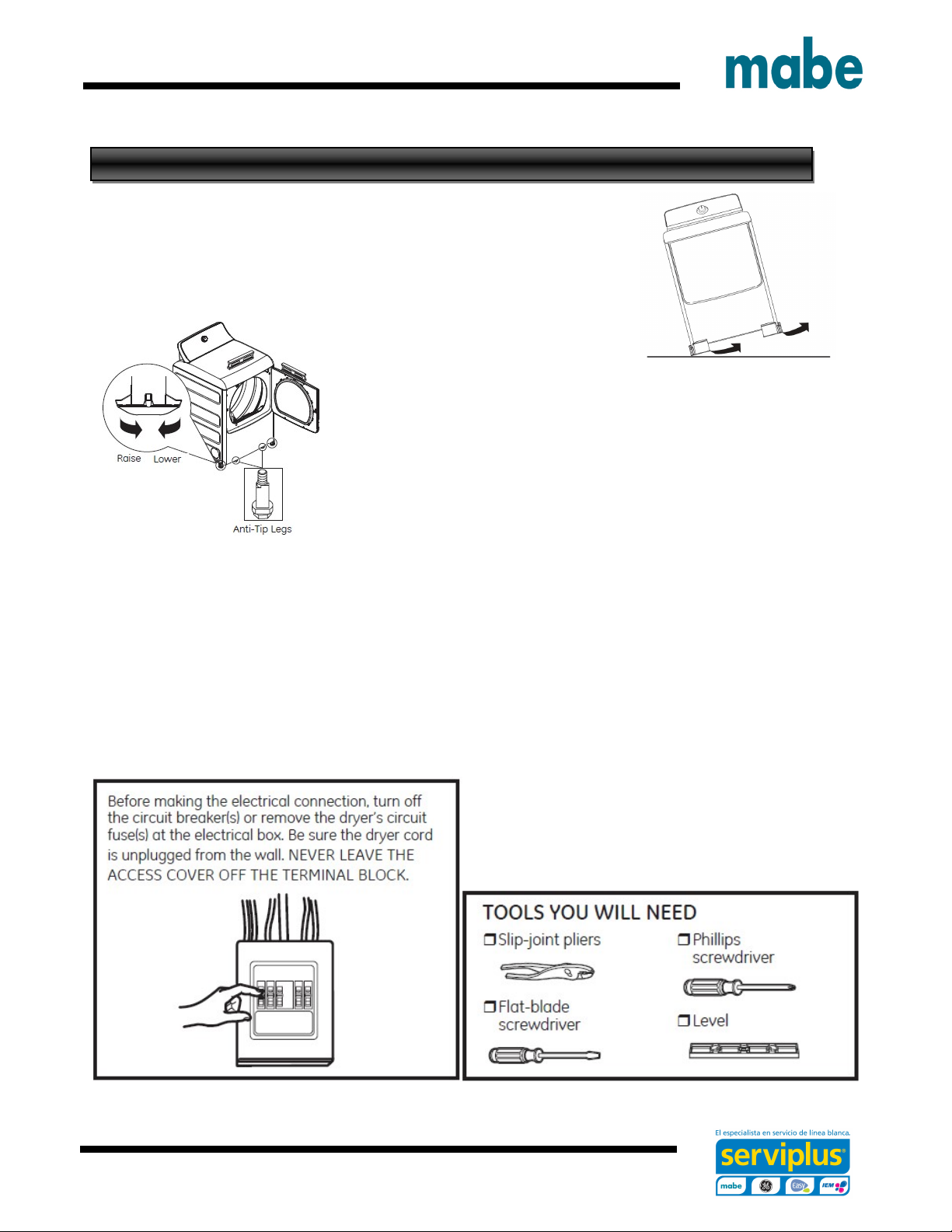
• Place the Dryer at designated area.
Stand the dryer upright near the final location and adjust the leveling legs at
the corners to ensure the dryer is level side-to-side and front-to-back. Then,
adjust the two anti-tip legs at the front inner corners, taking care that they are
touching the floor to avoid unit tip over. The installation is not complete until
this process is finished.
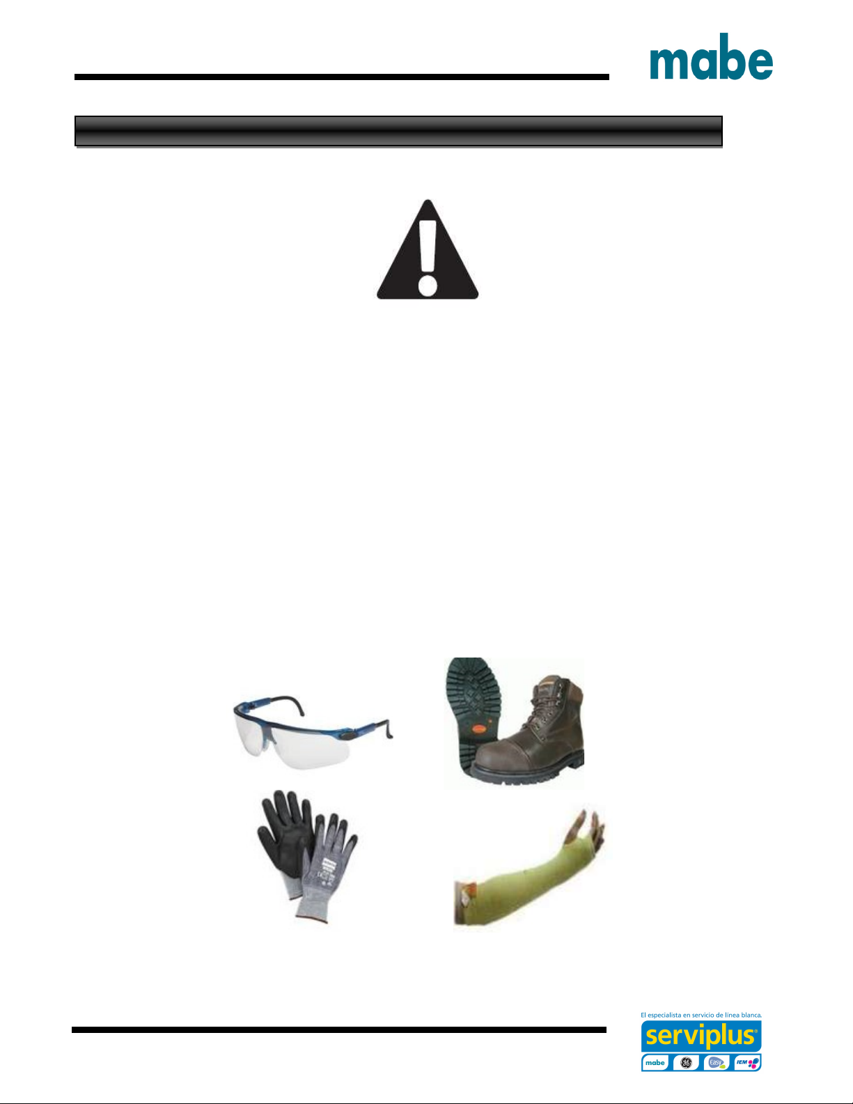
Warning: to avoid the risk of ignition and personal injury:
This dryer must be exhausted to the outdoors.
Before the old dryer is removed from service or discarded, remove the dryer door.
Service information and the wiring diagram are located in the control console.
The vent duct material MUST BE METAL.
This dryer must be grounded. In the event of a malfunction or breakdown, grounding will reduce the risk
of electric shock by providing a path of least resistance for electric current.
Install the dryer where the temperature is above 10°C for satisfactory operation of the dryer control
system.
Remain the area beneath and around the dryer without flammable substances as lint, paper, solvents,
chemicals, gasoline or other flammable liquids.
The exhaust vent MUST be securely fastened to a non-combustible portion of the mobile home.

Service Engineering
- 10
-

Service Engineering
- 11
-
For electrical connections using a power cord:
Disconnect power before making electrical connections.
Connect neutral wire (white or center wire) to center terminal.
Ground wire (green or bare wire) must be connected to green ground connector.
Connect remaining two supply wires to remaining two terminals.
Securely tighten all electrical connections.
Replace the terminal block cover.
GROUNDING INSTRUCTIONS
For a grounded, cord-connected dryer: This dryer must be grounded. In the event of a malfunction or
breakdown, grounding will reduce the risk of electric shock by providing a path of least resistance for electric
current. This dryer uses a cord having an equipment-grounding conductor and a grounding plug. The plug must
be plugged into an appropriate outlet that is properly installed and grounded in accordance with all local codes
and ordinances.
WARNING
Improper connection of the equipment-grounding conductor can result in a risk of electric shock. Check with a
qualified electrician, or service representative or personnel, if you are in doubt as to whether the appliance is
properly grounded. DO NOT modify the plug on the power supply cord. If it will not fit the outlet, have a proper
outlet installed by a qualified electrician.
For direct wire connections:
Use 10-gauge copper wire.
Use a strain relief.
Disconnect power before making electrical connections.
Connect neutral wire (white or center wire) to center terminal.
Ground wire (green or bare wire) must be connected to green ground connector.
Connect remaining two supply wires to remaining two terminals.
Securely tighten all electrical connections.
Replace the terminal block cover.
Failure to do so can result in death, fire or electrical shock.
GROUNDING INSTRUCTIONS
For a permanently connected dryer: This dryer must be connected to a grounded metal, permanent wiring
system, or an equipment-grounding conductor must be run with the circuit conductors and connected to the
equipment-grounding terminal on the appliance.
WARNING Improper connection of the equipment-grounding conductor can result in a risk of electric shock.
Check with a qualified electrician, or service representative or personnel, if you are in doubt as to whether the
appliance is properly grounded.

Service Engineering
- 12
-
CONNECTING DRYER.
If required, by local code, install external ground (not provided) to grounded metal, cold water pipe, or other
established ground determined by a qualified electrician.
1. Turn off the circuit breaker(s) (30 amp) or remove the dryer’s circuit fuse at the electrical box.
2. Be sure the dryer cord is unplugged from the wall receptacle.
3. Remove the power cord cover located at the lower back.
4. Install 3/4-in. UL-recognized strain relief to power cord entry hole. Bring power cord through strain relief.
5. Connect power cord as follows:
A. Connect the 2 hot lines to the outer screws of the terminal block (marked L1 and L2).
B. Connect the neutral (white) line to the center of the terminal block (marked N).
6. Be sure ground strap is connected to neutral (center) terminal of block and to green ground screw on
cabinet rear. Tighten all terminal block screws (3) securely.
7. Properly secure power cord to strain relief.
8. Reinstall the cover.
NEVER LEAVE THE COVER OFF OF THE TERMINAL BLOCK.

Service Engineering
- 13
-
EXHAUSTING THE DRYER
Using exhaust longer than specified length will:
• Increase the drying times and the energy cost.
• Reduce the dryer life.
• Accumulate lint, creating a potential fire hazard.
The correct exhaust installation is YOUR RESPONSIBILITY.
Problems due to incorrect installation are not covered by the warranty.
The MAXIMUM ALLOWABLE length of
the exhaust system depends upon the
type of duct, number of turns, the type of
exhaust hood (wall cap) and all conditions
noted on the chart.
Internal elbows added for side or
bottom vent conversions must be included
in the total elbow count.
Any elbow greater than 45°
should be treated as a 90° elbow.
Two 45° elbows will be treated
like one 90° elbow.
For every additional 90° elbow,
reduce the allowable vent system length
by 3 m.
When calculating the total vent
system length, you must add all the
straight portions and elbows of the system
(including the transition duct).
EXHAUST SYSTEM CHECKLIST
Hood or wall cap
• Terminate in a manner to prevent back drafts or entry of birds or other wildlife.
• Termination should present minimal resistance to the exhaust airflow and should require little or no
maintenance to prevent clogging.
• Wall caps must be installed at least 30.5 cm above ground level or any other obstruction with the opening
pointed down.
Separation of turns
• For best performance, separate all turns by at least 1.2 m. of straight duct, including distance between
last turn and dampened wall cap.
Sealing of joints
• All joints should be tight to avoid leaks. The male end of each section of duct must point away from the
dryer.
• Duct joints should be made air- and moisture-tight by wrapping the overlapped joints with duct tape or
aluminum tape.
• Do not assemble ductwork with any fasteners that extend into the duct. These fasteners can accumulate
lint, creating a potential fire hazard.
• Horizontal runs should slope down towards the outdoors 1/4” per foot.
• Provide an access for inspection and cleaning of the exhaust system, especially at turns and joints.
Exhaust system shall be inspected and cleaned at least once a year.
Insulation
• Ductwork that runs through an unheated area or is near air conditioning should be insulated to reduce
condensation and lint buildup.

Service Engineering
- 14
-
STANDARD REAR EXHAUST
We recommend that you install your dryer before installing your washer. This will permit direct access for
easier exhaust connection.
Slide the end of the exhaust duct on the back of the dryer and secure with duct tape or a duct clamp.
NOTE: We strongly recommend using rigid metal exhaust duct. However, if flexible ducting is used it must
be UL-Listed metal, not plastic.
• For straight-line installation, connect the dryer exhaust to the wall, using duct tape or a duct clamp.

Service Engineering
- 15
-
REVERSING THE DOOR
REVERSING THE DOOR SOLID DOOR MODELS
1. Open the door approximately 130 degrees. With a putty
knife, remove the 4 plastic caps located along the left
side of the front panel and set them aside.
2. Remove the bottom screw from each hinge
(right side) and partially insert them into
each top hinge hole on the left side.
NOTE: All 4 front panel hinge screws will
now be in the top hinge holes - 2 on the left
and 2 on the right.
3. Loosen each top hinge screw on right side. Remove the
door and place it on a protective flat surface to avoid any
damage.
4. Remove both the blind plate and the strike plate and
install them in opposite positions.
5. Mount the door on the 2 upper left side hinge
screws installed in step 2. Move the hinge screws
loosened in step 3 into the lower left side screw
holes and firmly tighten all 4 screws.
6. Install the 4 plastic caps removed in step 1 into
the 4 right side front panel holes.
NOTE: To return the door to the original setup, follow these instructions, swapping “left” and “right”.

Service Engineering
- 16
-
REVERSING THE DOOR - GLASS PANEL DOOR MODELS
1. Open the door approximately 130 degrees. With a putty knife,
remove the 4 plastic caps located along the left side of the front
panel and set them aside.
2. Remove the bottom screw from each hinge (right side) and
partially insert them into each top hinge hole on the left side
NOTE: All 4 front panel hinge screws will now be in the top hinge holes -
2 on the left and 2 on the right.
3. Loosen each top hinge screw on right side. Remove
the door and place it on a protective flat surface to
avoid any damage.
4. Remove both the blind plate and the strike plate and
install them in the opposite positions.
5. Remove the 4 door hinge screws, 6 inside screws
and 2 pocket screws. Lift the inner door upwards
using a flat blade screwdriver.
6. Remove and swap the 2 plastic caps and the 2 hinges.

Service Engineering
- 17
-
7. Rotate the outer door 180 degrees, mount the inner
door back into the outer door frame and secure with the
screws removed in step 5. Make sure you mount the
hinges on the side opposite the pocket.
8. Mount the assembled door on the 2 upper left side
hinge screws installed in step 2. Move the hinge
screws loosened in step 2 into the lower left side
screw holes and firmly tighten all 4 screws.
9. Install the 4 plastic caps removed in step 1 into the 4 right side front panel holes.
NOTE: To return the door to the original setup, follow these instructions, swapping “left” and “right”.

Service Engineering
- 18
-
TECHNICAL SPECIFICATIONS
Model Electrical
Requeriments
Dry
Sistem
Maximum
load
MKR62GWTWB
220-240V/50 Hz Electric 10kg
MKR62FWTWB
220-240V/60 Hz Electric 10kg
XKR72GWTWB
220-240V/50 Hz Electric 11kg
XKR72FWTWB
220-240V/60 Hz Electric 11kg
Technical Specification
Operational
Frequency
60Hz
50Hz
Supply
Voltage
220V~
220V~
Nominal
current
24A 24A
THE DRYER OPERATION
On front view the drum rotates clockwise at 48 to 54 rpm. The air is impulse through the electrical heating
resistance and send it to the clothes absorbing the humidity and lint.
The lint is filtered to outside when the air goes through the drum to the filter grill and blower duct to exhaust in the
vent duct.
The thermostat controls the air temperature according with the load size program selector. The time cycle length
is controlled by the minutes selected on the timer or an automatic control by the timer and the thermostat for the
type of clothes selected (Automatic Drying Cycles).
Exahust duct
Electric Heater
Air Entry

Service Engineering
- 19
-
D
EASSEMBLY AND FUNCTIONALITY
THE DRYER COMPONENTS
To access at the inner of the dryer you will need to remove two screws at the front panel of the washer.
Also remove the two screws of the backsplash dryer.
Tilt the backsplash with precaution to the top cover, the harness still connected to the main board.

Service Engineering
- 20
-
Unplug the harness from the timmer and selectors, retrive the harness carefully.
Remove the screws from the covers to free the harness.
Remove the screws form the drum cover to remove easily the drum.
This manual suits for next models
3
Table of contents
Other mabe Dryer manuals