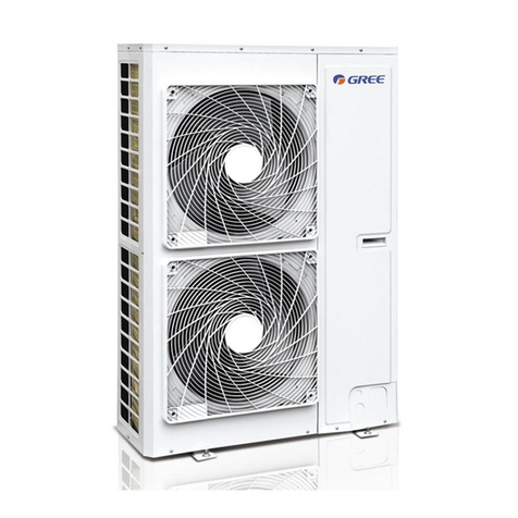
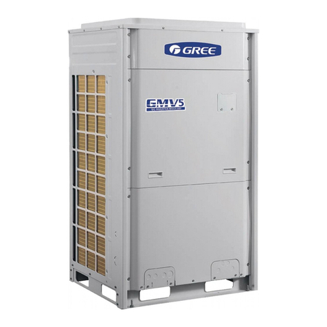
Gree GMV-Pdm224W/NaB-M User manual

DC INVERTER MULTIVRFSERVICE MANUAL
T1/R410A/50Hz
( GC201107 - )
CENTRAL AIR CONDITIONERS

CONTENTS
PRODUCT�������������������������������������������������������������������������������������������������������������������2
1 MODELS LIST�������������������������������������������������������������������������������������������������������������������������2
1�1 Outdoor Unit������������������������������������������������������������������������������������������������������������������������������������� 2
2 NOMENCLATURE������������������������������������������������������������������������������������������������������������������5
2�1 Nomenclature of Outdoor Unit�������������������������������������������������������������������������������������������������������� 5
3 FUNCTION�������������������������������������������������������������������������������������������������������������������������������5
4 PRODUCT DATA���������������������������������������������������������������������������������������������������������������������6
4�1 Product Data of Outdoor Unit��������������������������������������������������������������������������������������������������������� 6
5 PIPING DIAGRAM ���������������������������������������������������������������������������������������������������������������16
5�1 Piping diagram of GMV-Pdm224W/NaB-M,GMV-Pdm280W/NaB-M�������������������������������������16
5�2 Piping diagram of GMV-Pdm335W/NaB-M,GMV-Pdm400W/NaB-M,GMV-Pdm450W/
NaB-M�����������������������������������������������������������������������������������������������������������������������������������������������������17
CONTROL�����������������������������������������������������������������������������������������������������������������20
1 CONTROL OFTHE UNIT����������������������������������������������������������������������������������������������������20
1�1 Concept of Integral Control of the Unit ����������������������������������������������������������������������������������������20
1�2 Operation Flow Chart of the Unit��������������������������������������������������������������������������������������������������22
1�3 Operation Flow Chart of Outdoor Unit�����������������������������������������������������������������������������������������26
2 WIREDLESS REMOTE CONTROLLER ��������������������������������������������������������������������������28
2�1 Wiredless Remote Controller Y512������������������������������������������������������������������������������������������������28
2�2 Wiredless Remote Controller YB1FA��������������������������������������������������������������������������������������������31
3 WIRED REMOTE CONTROLLER������������������������������������������������������������������������������������36
3�1 Wired Controller Z60351F,Z60151F,Z63351F,Z63151F���������������������������������������������������������������36
3�2 Wired Controller XK02 ������������������������������������������������������������������������������������������������������������������38
4 REGIONAL CONTROLLER �����������������������������������������������������������������������������������������������42
4�1 Function��������������������������������������������������������������������������������������������������������������������������������������������42
4�2 Operation View��������������������������������������������������������������������������������������������������������������������������������43
4�3 Display View�������������������������������������������������������������������������������������������������������������������������������������44
4�4 Connection Between Controller and Unit ������������������������������������������������������������������������������������45
5 SMART ZONE CONTROLLER������������������������������������������������������������������������������������������46
5�1 Function��������������������������������������������������������������������������������������������������������������������������������������������46
5�2 Operation View �������������������������������������������������������������������������������������������������������������������������������46
5�3 Display View������������������������������������������������������������������������������������������������������������������������������������47
5�4 Network Topological Diagram��������������������������������������������������������������������������������������������������������48
5�5 Installation and Debugging�������������������������������������������������������������������������������������������������������������49
5�6 Attachment ���������������������������������������������������������������������������������������������������������������������������������������53
6 CENTRALIZED CONTROLLER ���������������������������������������������������������������������������������������54
6�1 Central Control ZJ7011 ������������������������������������������������������������������������������������������������������������������54
6�2 Centralized Controller CE51-24/E(M)������������������������������������������������������������������������������������������57
6�3 Connection Between Controller and Unit ������������������������������������������������������������������������������������68

6�4 Case Study����������������������������������������������������������������������������������������������������������������������������������������68
7 MONITORING SOFTWARE �����������������������������������������������������������������������������������������������84
7�1 Remote Monitoring System ������������������������������������������������������������������������������������������������������������84
7�2 BMS System �������������������������������������������������������������������������������������������������������������������������������������84
8 DETECTION CONTROL BOARD��������������������������������������������������������������������������������������85
8�1 Gate-control Function ��������������������������������������������������������������������������������������������������������������������85
8�2 Working Process of Gate Control ��������������������������������������������������������������������������������������������������85
8�3 Detection Control Board Interface Sketch is shown in Fig�2:�����������������������������������������������������86
8�4 Products Parameters ����������������������������������������������������������������������������������������������������������������������86
8�5 Installation of Detection Control Board ���������������������������������������������������������������������������������������86
INSTALLATION ������������������������������������������������������������������������������������������������������89
1 PRECAUTIONS FOR INSTALLATION�����������������������������������������������������������������������������89
1�1 Precautions for Safety ���������������������������������������������������������������������������������������������������������������������89
1�2 Key Points of Installation����������������������������������������������������������������������������������������������������������������90
2 FLOW CHART OF INSTALLATION����������������������������������������������������������������������������������91
3 INSTALLATION OF OUTDOOR UNIT ����������������������������������������������������������������������������92
3�1 Hoisting of Unit �������������������������������������������������������������������������������������������������������������������������������92
3�1 Installation of Outdoor Unit with SideAir Outlet������������������������������������������������������������������������93
3�2 Selection of Installation Site �����������������������������������������������������������������������������������������������������������93
3�3 Dimensions Data �����������������������������������������������������������������������������������������������������������������������������94
3�4 Clearance Data���������������������������������������������������������������������������������������������������������������������������������95
3�5 Take Monsoons and Snow into Consideration �����������������������������������������������������������������������������97
4 INSTALLATION REQUIREMENTS OF REFRIGERANT PIPING�������������������������������98
4.1 Specication ������������������������������������������������������������������������������������������������������������������������������������98
4�2 Allowable Length and Height Differences of the Refrigerant Piping between the Indoor and
Outdoor Units ����������������������������������������������������������������������������������������������������������������������������������������98
4�3 Refrigerant Pipe Size����������������������������������������������������������������������������������������������������������������������100
4�4 Selection of Y-Type Branch Pipe ��������������������������������������������������������������������������������������������������100
4�5 Selection of Refrigerant Piping between Outdoor Unit and Outdoor Unit ( for module unit)
����������������������������������������������������������������������������������������������������������������������������������������������������������������101
4�6� Outdoor unit piping sequence diagram���������������������������������������������������������������������������������������102
4�7 Design requirements for oil trap���������������������������������������������������������������������������������������������������103
5 INSTALLATION OF REFRIGERANT PIPING �������������������������������������������������������������105
5�1 Flow Chart of Installation �������������������������������������������������������������������������������������������������������������105
5�2 Three Principles of Refrigerant Piping Installation �������������������������������������������������������������������106
5�3 Installation of Metal Embedded Pipe �������������������������������������������������������������������������������������������106
5�4 Installation of Carriage of Refrigerant pipin ������������������������������������������������������������������������������106
5�5 Management and Machining of Refrigerant Piping �������������������������������������������������������������������107
5�6 Installation of Refrigerant Piping�������������������������������������������������������������������������������������������������111
5�7 Welding of Copper Pipe �����������������������������������������������������������������������������������������������������������������113
5�8 Cleaning of Refrigerant Piping ����������������������������������������������������������������������������������������������������117
5�9 Pressure Maintaining and Leak Hunting ������������������������������������������������������������������������������������118

5�10 Heat Preservation of Refrigerant Piping �����������������������������������������������������������������������������������119
5�11 Vacuum Pumping �������������������������������������������������������������������������������������������������������������������������120
5�12 Refrigerant Charge ����������������������������������������������������������������������������������������������������������������������121
6 INSTALLATION OF CONDENSATE PIPE ��������������������������������������������������������������������123
6�1Material Quality Requirements for Condensate Pipe������������������������������������������������������������������123
6�2 Key Points for Condensate Pipe Installation��������������������������������������������������������������������������������123
6�3 Test for Condensate Pipe����������������������������������������������������������������������������������������������������������������126
6�4 Requirements of Heat preservation ���������������������������������������������������������������������������������������������126
7 ELECTRICAL INSTALLATION ��������������������������������������������������������������������������������������127
7�1 Precautions for Electrical Installation������������������������������������������������������������������������������������������127
7.2 Specications Of Power Cord & Circuit Breaker �����������������������������������������������������������������������127
7�3 Wiring Sketch Map�������������������������������������������������������������������������������������������������������������������������128
7�4 Dial-up of Unit ��������������������������������������������������������������������������������������������������������������������������������137
ENGINEERING DEBUGGING����������������������������������������������������������������������������143
1 NECESSITY OF ENGINEERING DEBUGGING FOR VRF UNITS����������������������������143
2 ILES AND TOOLS FOR ENGINEERING DEBUGGING����������������������������������������������143
2�1 Tools �������������������������������������������������������������������������������������������������������������������������������������������������143
2�2 Debugging Files�������������������������������������������������������������������������������������������������������������������������������143
3 STEPS OF ENGINEERING DEBUGGING����������������������������������������������������������������������143
3�1 Preparation before Debugging ������������������������������������������������������������������������������������������������������143
3�2 Inspection before Debugging���������������������������������������������������������������������������������������������������������144
3�3 Debugging����������������������������������������������������������������������������������������������������������������������������������������149
3�4 Debugging of Cooling Mode ��������������������������������������������������������������������������������������������������������150
3�5 Running of Heating Mode��������������������������������������������������������������������������������������������������������������153
3�6 When the debugging is finished, sort out and save the data� Record the trouble and
troubleshooting during the debugging for future reference� Then, make a debugging report and
turn over it to users�������������������������������������������������������������������������������������������������������������������������������153
4� MAIN PARAMETERS AND REFERENCE VALVES FOR DEBUGGING�����������������154
5 COMMON TROUBLES DURING DEBUGGING�����������������������������������������������������������156
5�1 Communication ������������������������������������������������������������������������������������������������������������������������������156
5�2 System����������������������������������������������������������������������������������������������������������������������������������������������159
6 PORTABLE DEBUGGER���������������������������������������������������������������������������������������������������165
6�1� Function Introduction�������������������������������������������������������������������������������������������������������������������165
6�2 Display and Button������������������������������������������������������������������������������������������������������������������������165
6�3 Debugger Connection���������������������������������������������������������������������������������������������������������������������166
MAINTENANCE ���������������������������������������������������������������������������������������������������168
1 TROUBLE SHOOTING������������������������������������������������������������������������������������������������������168
1�1 Trouble Display of Indoor Unit �����������������������������������������������������������������������������������������������������168
1�2 Trouble Display of Mainboard LED of Outdoor Unit�����������������������������������������������������������������169
1�3 Number of indoor units display ����������������������������������������������������������������������������������������������������171
1�4 When the patching board is not communicated with indoor unit, if the complete unit stops,
the address code of patch board and “E6” will be displayed alternately (as shown in Fig 1), and
that is normal condition�����������������������������������������������������������������������������������������������������������������������171
2 FLOW CHART OFTROUBLESHOOTING �������������������������������������������������������������������173
2�1 High-pressure Protection���������������������������������������������������������������������������������������������������������������173
2�2 Low-pressure Protection����������������������������������������������������������������������������������������������������������������175
2�3 Exhaust Temperature Protection��������������������������������������������������������������������������������������������������177
2�4 Communication Failure�����������������������������������������������������������������������������������������������������������������178
2�5 Temperature sensor Trouble����������������������������������������������������������������������������������������������������������179
2�6 Sensor Trouble ��������������������������������������������������������������������������������������������������������������������������������180
2�7 No energization to the unit and mainboard ���������������������������������������������������������������������������������181
2�8 TheAC contactor does not pull in�������������������������������������������������������������������������������������������������182
2�9 Typical troubleshooting (E5) for DC frequency conversion drive board����������������������������������183
2�10 E5 Protection���������������������������������������������������������������������������������������������������������������������������������188
2�11 PFC Protection������������������������������������������������������������������������������������������������������������������������������190
2�12 IPM Protecion�������������������������������������������������������������������������������������������������������������������������������191
2�13 Trip�������������������������������������������������������������������������������������������������������������������������������������������������192
2�14 Superheat Protection of Radiator�����������������������������������������������������������������������������������������������193
2�15 DC Overvoltage Protection ���������������������������������������������������������������������������������������������������������194
3 POWER DISTRIBUTION���������������������������������������������������������������������������������������������������195
3�1 Diagram of Power Distribution�����������������������������������������������������������������������������������������������������195
3�2 Introduction of Main Electric Parts of Inverter System�������������������������������������������������������������195
3�3 Wiring diadram ������������������������������������������������������������������������������������������������������������������������������196
4 TABLE OFTHE RESISTANCES OF COMMON TEMPERATURE SENSORS���������198
4.1. 15k������������������������������������������������������������������������������������������������������������������������������������������������198
4.2. 20k������������������������������������������������������������������������������������������������������������������������������������������������200
4.3. 50k������������������������������������������������������������������������������������������������������������������������������������������������202
5 FEATURES OF THE HIGHT/LOW PRESSURE SENSORS�����������������������������������������204
5�1 Features of the High Pressure Sensors (R410a)���������������������������������������������������������������������������204
5�2 Features of the Low Pressure Sensors (R410a)����������������������������������������������������������������������������205
6 AFTER-SALES EMERGENCY MEASURES������������������������������������������������������������������� 206
7 DISASSEMBLYAND ASSEMBLY PROCEDURE OF MAIN PARTS �������������������������207
7� 1 Outdoor Unit����������������������������������������������������������������������������������������������������������������������������������207
8 EXPLODED VIEWS AND PART LIST ����������������������������������������������������������������������������216
8�1 Outdoor Unit ����������������������������������������������������������������������������������������������������������������������������������216

DC Inverter Multi
VRF Service Manual
1
PRODUCT
PRODUCT

2
DC Inverter Multi
VRF Service Manual
PRODUCT
PRODUCT
1 MODELS LIST
1�1 Outdoor Unit
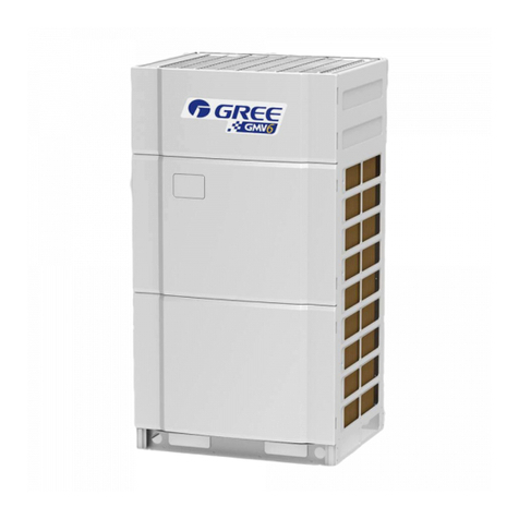
Modle Product Code
Cooling
Capacity Heating
Capacity Power
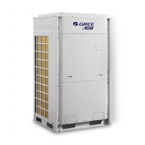
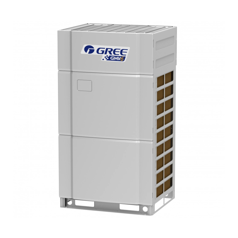
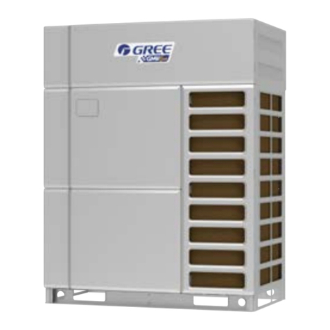
supply Appearance
kW kW
GMV-Pdm224W/NaB-M CN851W1000 22.4 25.0 380~415V-3Ph~50Hz
GMV-Pdm280W/NaB-M CN851W1010 28.0 31.5 380~415V-3Ph~50Hz
GMV-Pdm335W/NaB-M CN851W1020 33.5 37.5 380~415V-3Ph~50Hz
GMV-Pdm400W/NaB-M CN851W1030 40.0 45.0 380~415V-3Ph~50Hz
GMV-Pdm450W/NaB-M CN851W1040 45.0 50.0 380~415V-3Ph~50Hz

DC Inverter Multi
VRF Service Manual
3PRODUCT
Appearance Model GMV-Pdm***W/NaB-M
224 280 335 400 450
504
560
615
670
730
785
850
900
950
1008
1065
1130
1180
1235
1300
1350
GMV-Pdm***W2/NaB-MGMV-Pdm***W3/NaB-M

4
DC Inverter Multi
VRF Service Manual
PRODUCT
Appearance Model GMV-Pdm***W/NaB-M
224 280 335 400 450
1405
1456
1512
1570
1650
1700
1750
1800
NOTES:
a.“ ”represents one module and“ … (1…N)”represents N modules.
b.“*”indicates the rated cooling capacity.
c.Design of this unit accords with the Standard GB/T 18837-2002.
d.Noise was tested in semi-silenced room, so the actual noise value will be a little higher for change of
environment..
e.The charge amount of R410A in the list is only the sealed amount when outdoor unit is outgoing. When
installing, calculate
f.the additional charge amount according to actual length of pipe and the matched indoor units;
g.Nominal capacities are based on the following conditions.
CAUTIONS
It is not recommended to adopt the combination mode not specied by this manual.
GMV-Pdm***W4/NaB-M

DC Inverter Multi
VRF Service Manual
5PRODUCT
2 NOMENCLATURE
2�1 Nomenclature of Outdoor Unit
GMV - 224 W / Na B -
1 2 3 4 5 6 7 8 9
NO. Description Options
1 Code for type GMV: Gree Multi Variable
2 Code for model L: Cooling Only, Default: Heat pump
3 Units Series Pdm: Modular D.C. Inverter Multi-variable
4 Nominal cooling capacity 224: 22.4 kW......450:45.0kW
5 Outdoor unit W: Outdoor unit
6 Model quantity of the Pdm series unit
Default:One module
2:Two modules
3:Three modules
4:Four modules
7 Refrigerant Na: R410A
8 Series number B: Product serial number
9 Power supply M:3808-415V 3Ph~ 50Hz
3 FUNCTION
For Comfortable Air Conditioning
Auto Restart
Fan Operation Mode
LCD Remote Controller (Option)
Auto Swing Function
Ceiling Soiling Prevention
Program Dry
High Fan Speed Mode
High Ceiling Application
Two Select Thermal Sensor
Hot Start
Timer Selector
For Easy Construction and Maintenance
Fresh Air Intake Directly from The Unit
Drain Pump
Long Life Filter
Ultra-Long life Filter (Option)
Mold Resistant Treatment for Filter
Filter Sign
Mold Resistant Drain Pan
Emergency Operation
Self Diagnoses Function
For Flexible Control
Set Back Time Clock
Double Remote Control
Group Control By 1 Remote Controller
Control By External Command
Remote/Centralized Control

6
DC Inverter Multi
VRF Service Manual
PRODUCT
4 PRODUCT DATA
4�1 Product Data of Outdoor Unit
Model(Combined unit) — — —
Model GMV-Pdm224W/NaB-M GMV-Pdm280W/NaB-M GMV-Pdm335W/NaB-M
Capacity
Cooling kW 22.4 28 33.5
kBtu/h 76.43 95.536 114.302
Heating kW 25 31.5 37.5
kBtu/h 85.3 107.478 127.95
Sound Pressure Level dB(A) 58 58 60
Power Supply V/Hz/Ph 380-415V~50Hz-3Ph
Power input Cooling kW 5.52 7.52 9.23
Heating kW 5.82 7.7 9.38
Current Cooling A 9.87 13.44 16.50
Heating A 10.4 13.76 16.77
Circuit breaker A 32 32 40
Recommended
Power Lines mm2×N 6×5 6×5 10×5
Moisture protection IP24 IP24 IP24
Climate Type T1 T1 T1
Connecting
pipe
Gas Pipe mm Φ22.2 Φ22.2 Φ28.6
Inch 7/8 7/8 9/8
Liquid
Pipe mm Φ9.52 Φ9.52 Φ12.7
Inch 3/8 3/8 1/2
Oil Pipe mm — — —
Inch — — —
Connection Method Brazing Connection Brazing Connection Brazing Connection
Dimensions
of Unit
Width mm 930 930 1340
Depth mm 770 770 770
Height mm 1670 1670 1670
Dimensions
of Package
Width mm 1010 1010 1420
Depth mm 850 850 850
Height mm 1850 1850 1850
Net Weight kg 255 255 350
Gross Weight kg 275 275 380
Loading Quantity
( 20’Container ) unit 12 12 7
Loading Quantity
( 40’Container ) unit 24 24 16
Loading Quantity ( 40’
High Cube Container ) unit 24 24 16
Notes:
① .
The sound level is tested under circumstance of semi-anechoic chamber; the value of noise could be a little
higher in actual operation.
② .
The data will change with the change of products. Refer to those parameters listed on nameplate.
③ .
The charge amount of refrigerant in the list is the datum when there is not drop height vertically between
indoor unit and outdoor unit, without consideration of connection pipe. So calculate the additional charge amount
according to actual condition during installation.
④ .
Section area of lead wire is only applicable for 15-m distance.If above, increase the section area to avoid
overload of current which would cause burnout of lead wire.
⑤ .
The outdoor fan of this unit is without static pressure.If static pressure is required, please specially notice it on
purchase order.
⑥ .
Running condition of cooling: outdoor temperature -5 ~48 ; Running condition of heating: outdoor
temperature -20 ~27 .

DC Inverter Multi
VRF Service Manual
7PRODUCT
Model(Combined unit) — — GMV-Pdm504W2/NaB-M
Model GMV-Pdm400W/NaB-M GMV-Pdm450W/NaB-M GMV-Pdm224W/NaB-M
+GMV-Pdm280W/NaB-M
Capacity
Cooling kW 40 45 50.4
kBtu/h 136.48 153.54 171.964
Heating kW 45 50 56.5
kBtu/h 153.54 170.6 192.778
Sound Pressure Level dB(A) 61 61 62
Power Supply V/Hz/Ph 380-415V~50Hz-3Ph
Power input Cooling kW 12.45 14.32 5.52+7.52
Heating kW 11.2 13.9 5.82+7.70
Current Cooling A 22.25 25.6 9.87+13.44
Heating A 20.02 24.85 10.4+13.76
Circuit breaker A 40 40 32+32
Recommended
Power Lines mm2×N 10×5 10×5 6×5+6×5
Moisture protection IP24 IP24 IP24
Climate Type T1 T1 T1
Connecting
pipe
Gas Pipe mm Φ28.6 Φ28.6 Φ28.6
Inch 9/8 9/8 9/8
Liquid
Pipe
mm Φ12.7 Φ12.7 Φ15.9
Inch 1/2 1/2 5/8
Oil Pipe mm — — Φ12.7
Inch — — 1/2
Connection Method Brazing Connection Brazing Connection Brazing Connection
Dimensions
of Unit
Width mm 1340 1340 930+930
Depth mm 770 770 770+770
Height mm 1670 1670 1670+1670
Dimensions
of Package
Width mm 1420 1420 1010+1010
Depth mm 850 850 850+850
Height mm 1850 1850 1850+1850
Net Weight kg 350 370 255+255
Gross Weight kg 380 400 275+275
Loading Quantity
( 20’Container ) unit 7 7 ——
Loading Quantity
( 40’Container ) unit 16 16 ——
Loading Quantity ( 40’
High Cube Container ) unit 24 24 ——
Notes:
① .
The sound level is tested under circumstance of semi-anechoic chamber; the value of noise could be a little
higher in actual operation.
② .
The data will change with the change of products. Refer to those parameters listed on nameplate.
③ .
The charge amount of refrigerant in the list is the datum when there is not drop height vertically between
indoor unit and outdoor unit, without consideration of connection pipe. So calculate the additional charge amount
according to actual condition during installation.
④ .
Section area of lead wire is only applicable for 15-m distance.If above, increase the section area to avoid
overload of current which would cause burnout of lead wire.
⑤ .
The outdoor fan of this unit is without static pressure.If static pressure is required, please specially notice it on
purchase order.
⑥ .
Running condition of cooling: outdoor temperature -5 ~48 ; Running condition of heating: outdoor
temperature -20 ~27 .

8
DC Inverter Multi
VRF Service Manual
PRODUCT
Model(Combined unit) GMV-Pdm560W2/NaB-M GMV-Pdm615W2/NaB-M GMV-Pdm670W2/NaB-M
Model GMV-Pdm280W/NaB-M
+GMV-Pdm280W/NaB-M GMV-Pdm280W/NaB-M
+GMV-Pdm335W/NaB-M GMV-Pdm280W/NaB-M
+GMV-Pdm400W/NaB-M
Capacity
Cooling kW 56.0 61.5 68.0
kBtu/h 191.072 209.838 232.016
Heating kW 63.0 69.0 76.5
kBtu/h 214.956 235.428 261.018
Sound Pressure Level dB(A) 62 62 62
Power Supply V/Hz/Ph 380-415V~50Hz-3Ph
Power input Cooling kW 7.52+7.52 7.52+9.23 7.52+12.45
Heating kW 7.70+7.70 7.70+9.38 7.70+11.2
Current Cooling A 13.44+13.44 13.44+16.50 13.44+22.25
Heating A 13.76+13.76 13.76+16.77 13.76+20.02
Circuit breaker A 32+32 32+40 32+40
Recommended
Power Lines mm2×N 6×5+6×5 6×5+10×5 6×5+10×5
Moisture protection IP24 IP24 IP24
Climate Type T1 T1 T1
Connecting
pipe
Gas Pipe mm Φ28.6 Φ28.6 Φ28.6
Inch 9/8 9/8 9/8
Liquid
Pipe
mm Φ15.9 Φ15.9 Φ15.9
Inch 5/8 5/8 5/8
Oil Pipe mm Φ12.7 Φ12.7 Φ12.7
Inch 1/2 1/2 1/2
Connection Method Brazing Connection Brazing Connection Brazing Connection
Dimensions
of Unit
Width mm 930+930 930+1340 930+1340
Depth mm 770+770 770+770 770+770
Height mm 1670+1670 1670+1670 1670+1670
Dimensions
of Package
Width mm 1010+1010 1010+1420 1010+1420
Depth mm 850+850 850+850 850+850
Height mm 1850+1850 1850+1850 1850+1850
Net Weight kg 255+255 255+350 255+350
Gross Weight kg 275+275 275+380 275+380
Loading Quantity
( 20’Container ) unit —— —— ——
Loading Quantity
( 40’Container ) unit —— —— ——
Loading Quantity ( 40’
High Cube Container ) unit —— —— ——
Notes:
① .
The sound level is tested under circumstance of semi-anechoic chamber; the value of noise could be a little
higher in actual operation.
② .
The data will change with the change of products. Refer to those parameters listed on nameplate.
③ .
The charge amount of refrigerant in the list is the datum when there is not drop height vertically between
indoor unit and outdoor unit, without consideration of connection pipe. So calculate the additional charge amount
according to actual condition during installation.
④ .
Section area of lead wire is only applicable for 15-m distance.If above, increase the section area to avoid
overload of current which would cause burnout of lead wire.
⑤ .
The outdoor fan of this unit is without static pressure.If static pressure is required, please specially notice it on
purchase order.
⑥ .
Running condition of cooling: outdoor temperature -5 ~48 ; Running condition of heating: outdoor
temperature -20 ~27 .

DC Inverter Multi
VRF Service Manual
9PRODUCT
Model(Combined unit) GMV-Pdm730W2/NaB-M GMV-Pdm785W2/NaB-M GMV-Pdm850W2/NaB-M
Model GMV-Pdm280W/NaB-M
+GMV-Pdm450W/NaB-M GMV-Pdm335W/NaB-M
+GMV-Pdm450W/NaB-M GMV-Pdm400W/NaB-M
+GMV-Pdm450W/NaB-M
Capacity
Cooling kW 73.0 80.0 85.0
kBtu/h 249.076 272.960 290.020
Heating kW 81.5 90.0 95.0
kBtu/h 278.078 307.080 324.140
Sound Pressure Level dB(A) 63 63 63
Power Supply V/Hz/Ph 380-415V~50Hz-3Ph
Power input Cooling kW 7.52+14.32 9.23+14.32 12.45+14.32
Heating kW 7.70+13.90 9.38+13.90 11.20+13.90
Current Cooling A 13.44+25.6 16.50+25.60 22.25+25.60
Heating A 13.76+24.85 16.77+24.85 20.02+24.85
Circuit breaker A 32+40 40+40 40+40
Recommended
Power Lines mm2×N 6×5+10×5 10×5+10×5 10×5+10×5
Moisture protection IP24 IP24 IP24
Climate Type T1 T1 T1
Connecting
pipe
Gas Pipe mm Φ34.9 Φ34.9 Φ34.9
Inch 11/8 11/8 11/8
Liquid
Pipe
mm Φ19.05 Φ19.05 Φ19.05
Inch 3/4 3/4 3/4
Oil Pipe mm Φ12.7 Φ12.7 Φ12.7
Inch 1/2 1/2 1/2
Connection Method Brazing Connection Brazing Connection Brazing Connection
Dimensions
of Unit
Width mm 930+1340 1340+1340 1340+1340
Depth mm 770+770 770+770 770+770
Height mm 1670+1670 1670+1670 1670+1670
Dimensions
of Package
Width mm 1010+1420 1420+1420 1420+1420
Depth mm 850+850 850+850 850+850
Height mm 1850+1850 1850+1850 1850+1850
Net Weight kg 255+370 350+370 350+370
Gross Weight kg 275+400 380+400 380+400
Loading Quantity
( 20’Container ) unit —— —— ——
Loading Quantity
( 40’Container ) unit —— —— ——
Loading Quantity ( 40’
High Cube Container ) unit —— —— ——
Notes:
① .
The sound level is tested under circumstance of semi-anechoic chamber; the value of noise could be a little
higher in actual operation.
② .
The data will change with the change of products. Refer to those parameters listed on nameplate.
③ .
The charge amount of refrigerant in the list is the datum when there is not drop height vertically between
indoor unit and outdoor unit, without consideration of connection pipe. So calculate the additional charge amount
according to actual condition during installation.
④ .
Section area of lead wire is only applicable for 15-m distance.If above, increase the section area to avoid
overload of current which would cause burnout of lead wire.
⑤ .
The outdoor fan of this unit is without static pressure.If static pressure is required, please specially notice it on
purchase order.
⑥ .
Running condition of cooling: outdoor temperature -5 ~48 ; Running condition of heating: outdoor
temperature -20 ~27 .

10
DC Inverter Multi
VRF Service Manual
PRODUCT
Model(Combined unit) GMV-Pdm900W2/NaB-M GMV-Pdm950W3/NaB-M GMV-Pdm1008W3/NaB-M
Model GMV-Pdm450W/NaB-M
+GMV-Pdm450W/NaB-M
GMV-Pdm280W/NaB-M
+GMV-Pdm280W/NaB-M
+GMV-Pdm400W/NaB-M
GMV-Pdm280W/NaB-M
+GMV-Pdm280W/NaB-M
+GMV-Pdm450W/NaB-M
Capacity
Cooling kW 90.0 96.0 101.0
kBtu/h 307.080 327.552 344.612
Heating kW 100.0 108.0 113.0
kBtu/h 341.200 368.496 385.526
Sound Pressure Level dB(A) 63 64 64
Power Supply V/Hz/Ph 380-415V~50Hz-3Ph
Power input Cooling kW 14.32+14.32 7.52+7.52+12.45 7.52+7.52+14.32
Heating kW 13.90+13.90 7.70+7.70+11.2 7.70+7.70+13.90
Current Cooling A 25.6+25.6 13.44+13.44+22.25 13.44+13.44+25.6
Heating A 24.85+24.85 13.76+13.76+20.02 13.76+13.76+24.85
Circuit breaker A 40+40 32+32+40 32+32+40
Recommended
Power Lines mm2×N 10×5+10×5 6×5+6×5+10×5 6×5+6×5+10×5
Moisture protection IP24 IP24 IP24
Climate Type T1 T1 T1
Connecting
pipe
Gas Pipe mm Φ34.9 Φ34.9 Φ41.3
Inch 11/8 11/8 13/8
Liquid
Pipe
mm Φ19.05 Φ19.05 Φ19.05
Inch 3/4 3/4 3/4
Oil Pipe mm Φ12.7 Φ12.7 Φ12.7
Inch 1/2 1/2 1/2
Connection Method Brazing Connection Brazing Connection Brazing Connection
Dimensions
of Unit
Width mm 1340+1340 930+930+1340 930+930+1340
Depth mm 770+770 770+770+770 770+770+770
Height mm 1670+1670 1670+1670+1670 1670+1670+1670
Dimensions
of Package
Width mm 1420+1420 1010+1010+1420 1010+1010+1420
Depth mm 850+850 850+850+850 850+850+850
Height mm 1850+1850 1850+1850+1850 1850+1850+1850
Net Weight kg 370+370 255+255+350 255+255+370
Gross Weight kg 400+400 275+275+380 275+275+400
Loading Quantity
( 20’Container ) unit —— —— ——
Loading Quantity
( 40’Container ) unit —— —— ——
Loading Quantity ( 40’
High Cube Container ) unit —— —— ——
Notes:
① .
The sound level is tested under circumstance of semi-anechoic chamber; the value of noise could be a little
higher in actual operation.
② .
The data will change with the change of products. Refer to those parameters listed on nameplate.
③ .
The charge amount of refrigerant in the list is the datum when there is not drop height vertically between
indoor unit and outdoor unit, without consideration of connection pipe. So calculate the additional charge amount
according to actual condition during installation.
④ .
Section area of lead wire is only applicable for 15-m distance.If above, increase the section area to avoid
overload of current which would cause burnout of lead wire.
⑤ .
The outdoor fan of this unit is without static pressure.If static pressure is required, please specially notice it on
purchase order.
⑥ .
Running condition of cooling: outdoor temperature -5 ~48 ; Running condition of heating: outdoor
temperature -20 ~27 .

DC Inverter Multi
VRF Service Manual
11 PRODUCT
Model(Combined unit) GMV-Pdm1065W3/NaB-M GMV-Pdm1130W3/NaB-M GMV-Pdm1180W3/NaB-M
Model GMV-Pdm280W/NaB-M
+GMV-Pdm335W/NaB-M
+GMV-Pdm450W/NaB-M
GMV-Pdm280W/NaB-M
+GMV-Pdm400W/NaB-M
+GMV-Pdm450W/NaB-M
GMV-Pdm280W/NaB-M
+GMV-Pdm450W/NaB-M
+GMV-Pdm450W/NaB-M
Capacity
Cooling kW 108.0 113.0 118.0
kBtu/h 368.469 385.556 402.616
Heating kW 121.5 126.5 131.5
kBtu/h 414.558 431.618 448.678
Sound Pressure Level dB(A) 64 64 64
Power Supply V/Hz/Ph 380-415V~50Hz-3Ph
Power input Cooling kW 7.52+9.23+14.32 7.52+12.45+14.32 7.52+14.32+14.32
Heating kW 7.70+9.38+13.9 7.70+11.2+13.9 7.70+13.90+13.90
Current Cooling A 13.44+16.50+25.6 13.44+22.25+25.6 13.44+25.6+25.6
Heating A 13.76+16.77+24.85 13.76+20.02+24.85 13.76+24.85+24.85
Circuit breaker A 32+40+40 32+40+40 32+40+40
Recommended
Power Lines mm2×N 6×5+10×5+10×5 6×5+10×5+10×5 6×5+10×5+10×5
Moisture protection IP24 IP24 IP24
Climate Type T1 T1 T1
Connecting
pipe
Gas Pipe mm Φ41.3 Φ41.3 Φ41.3
Inch 13/8 13/8 13/8
Liquid
Pipe
mm Φ19.05 Φ19.05 Φ19.05
Inch 3/4 3/4 3/4
Oil Pipe mm Φ12.7 Φ12.7 Φ12.7
Inch 1/2 1/2 1/2
Connection Method Brazing Connection Brazing Connection Brazing Connection
Dimensions
of Unit
Width mm 930+1340+1340 930+1340+1340 930+1340+1340
Depth mm 770+770+770 770+770+770 770+770+770
Height mm 1670+1670+1670 1670+1670+1670 1670+1670+1670
Dimensions
of Package
Width mm 1010+1420+1420 1010+1420+1420 1010+1420+1420
Depth mm 850+850+850 850+850+850 850+850+850
Height mm 1850+1850+1850 1850+1850+1850 1850+1850+1850
Net Weight kg 255+350+370 255+350+370 255+370+370
Gross Weight kg 275+380+400 275+380+400 275+400+400
Loading Quantity
( 20’Container ) unit —— —— ——
Loading Quantity
( 40’Container ) unit —— —— ——
Loading Quantity ( 40’
High Cube Container ) unit —— —— ——
Notes:
① .
The sound level is tested under circumstance of semi-anechoic chamber; the value of noise could be a little
higher in actual operation.
② .
The data will change with the change of products. Refer to those parameters listed on nameplate.
③ .
The charge amount of refrigerant in the list is the datum when there is not drop height vertically between
indoor unit and outdoor unit, without consideration of connection pipe. So calculate the additional charge amount
according to actual condition during installation.
④ .
Section area of lead wire is only applicable for 15-m distance.If above, increase the section area to avoid
overload of current which would cause burnout of lead wire.
⑤ .
The outdoor fan of this unit is without static pressure.If static pressure is required, please specially notice it on
purchase order.
⑥ .
Running condition of cooling: outdoor temperature -5 ~48 ; Running condition of heating: outdoor
temperature -20 ~27 .

12
DC Inverter Multi
VRF Service Manual
PRODUCT
Model(Combined unit) GMV-Pdm1235W3/NaB-M GMV-Pdm1300W3/NaB-M GMV-Pdm1350W3/NaB-M
Model GMV-Pdm335W/NaB-M
+GMV-Pdm450W/NaB-M
+GMV-Pdm450W/NaB-M
GMV-Pdm400W/NaB-M
+GMV-Pdm450W/NaB-M
+GMV-Pdm450W/NaB-M
GMV-Pdm450W/NaB-M
+GMV-Pdm450W/NaB-M
+GMV-Pdm450W/NaB-M
Capacity
Cooling kW 125.0 130.0 135.0
kBtu/h 426.500 443.560 460.620
Heating kW 14.0 145.0 150.0
kBtu/h 477.680 494.740 511.800
Sound Pressure Level dB(A) 65 65 65
Power Supply V/Hz/Ph 380-415V~50Hz-3Ph
Power input Cooling kW 9.23+14.32+14.32 12.45+14.32+14.32 14.32+14.32+14.32
Heating kW 9.38+13.9+13.9 11.2+13.9+13.9 13.90+13.90+13.90
Current Cooling A 16.5+25.6+25.6 22.25+25.6+25.6 25.6+25.6+25.6
Heating A 16.77+24.85+24.85 20.02+24.85+24.85 24.85+24.85+24.85
Circuit breaker A 40+40+40 40+40+40 40+40+40
Recommended
Power Lines mm2×N 10×5+10×5+10×5 10×5+10×5+10×5 10×5+10×5+10×5
Moisture protection IP24 IP24 IP24
Climate Type T1 T1 T1
Connecting
pipe
Gas Pipe mm Φ41.3 Φ41.3 Φ41.3
Inch 13/8 13/8 13/8
Liquid
Pipe
mm Φ19.05 Φ19.05 Φ19.05
Inch 3/4 3/4 3/4
Oil Pipe mm Φ12.7 Φ12.7 Φ12.7
Inch 1/2 1/2 1/2
Connection Method Brazing Connection Brazing Connection Brazing Connection
Dimensions
of Unit
Width mm 1340+1340+1340 1340+1340+1340 1340+1340+1340
Depth mm 770+770+770 770+770+770 770+770+770
Height mm 1670+1670+1670 1670+1670+1670 1670+1670+1670
Dimensions
of Package
Width mm 1420+1420+1420 1420+1420+1420 1420+1420+1420
Depth mm 850+850+850 850+850+850 850+850+850
Height mm 1850+1850+1850 1850+1850+1850 1850+1850+1850
Net Weight kg 350+370+370 350+370+370 370+370+370
Gross Weight kg 380+400+400 380+400+400 400+400+400
Loading Quantity
( 20’Container ) unit —— —— ——
Loading Quantity
( 40’Container ) unit —— —— ——
Loading Quantity ( 40’
High Cube Container ) unit —— —— ——
Notes:
① .
The sound level is tested under circumstance of semi-anechoic chamber; the value of noise could be a little
higher in actual operation.
② .
The data will change with the change of products. Refer to those parameters listed on nameplate.
③ .
The charge amount of refrigerant in the list is the datum when there is not drop height vertically between
indoor unit and outdoor unit, without consideration of connection pipe. So calculate the additional charge amount
according to actual condition during installation.
④ .
Section area of lead wire is only applicable for 15-m distance.If above, increase the section area to avoid
overload of current which would cause burnout of lead wire.
⑤ .
The outdoor fan of this unit is without static pressure.If static pressure is required, please specially notice it on
purchase order.
⑥ .
Running condition of cooling: outdoor temperature -5 ~48 ; Running condition of heating: outdoor
temperature -20 ~27 .

DC Inverter Multi
VRF Service Manual
13 PRODUCT
Model(Combined unit) GMV-Pdm1405W4/NaB-M GMV-Pdm1456W4/NaB-M GMV-Pdm1512W4/NaB-M
Model
GMV-Pdm280W/NaB-M
+GMV-Pdm280W/NaB-M
+GMV-Pdm400W/NaB-M
+GMV-Pdm450W/NaB-M
GMV-Pdm280W/NaB-M
+GMV-Pdm280W/NaB-M
+GMV-Pdm450W/NaB-M
+GMV-Pdm450W/NaB-M
GMV-Pdm280W/NaB-M
+GMV-Pdm335W/NaB-M
+GMV-Pdm450W/NaB-M
+GMV-Pdm450W/NaB-M
Capacity
Cooling kW 141.0 146.0 153.0
kBtu/h 481.092 498.152 522.036
Heating kW 158.0 163.0 171.0
kBtu/h 539.096 556.156 585.158
Sound Pressure Level dB(A) 65 65 65
Power Supply V/Hz/Ph 380-415V~50Hz-3Ph
Power input Cooling kW 7.52+7.52+12.45+14.32 7.52+7.52+14.32+14.32 7.52+9.23+14.32+14.32
Heating kW 7.707.70+11.2+13.9 7.70+7.70+13.90+13.90 7.70+9.38+13.90+13.90
Current Cooling A 13.44+13.44+22.25+25.6 13.44+13.44+25.6+25.6 13.44+16.50+25.6+25.6
Heating A 13.76+13.76+20.02+24.85 13.76+13.76+24.85+24.85 13.76+16.77+24.85+24.85
Circuit breaker A 31+32+40+40 32+32+40+40 32+40+40+40
Recommended
Power Lines mm2×N 6×5+6×5+10×5+10×5 6×5+6×5+10×5+10×5 6×5+10×5+10×5+10×5
Moisture protection IP24 IP24 IP24
Climate Type T1 T1 T1
Connecting
pipe
Gas
Pipe
mm Φ44.5 Φ44.5 Φ41.3
Inch 7/4 7/4 13/8
Liquid
Pipe
mm Φ22.2 Φ22.2 Φ19.05
Inch 7/8 7/8 3/4
Oil Pipe mm Φ12.7 Φ12.7 Φ12.7
Inch 1/2 1/2 1/2
Connection Method Brazing Connection Brazing Connection Brazing Connection
Dimensions
of Unit
Width mm 930+930+1340+1340 930+930+1340+1340 930+1340+1340+1340
Depth mm 770+770+770+770 770+770+770+770 770+770+770+770
Height mm 1670+1670+1670+1670 1670+1670+1670+1670 1670+1670+1670+1670
Dimensions
of Package
Width mm 1010+1010+1420+1420 1010+1010+1420+1420 1010+1420+1420+1420
Depth mm 850+850+850+850 850+850+850+850 850+850+850+850
Height mm 1850+1850+1850+1850 1850+1850+1850+1850 1850+1850+1850+1850
Net Weight kg 255+255+350+370 255+255+370+370 255+350+370+370
Gross Weight kg 275+275+380+400 275+275+400+400 275+380+400+400
Loading Quantity
( 20’Container ) unit —— —— ——
Loading Quantity
( 40’Container ) unit —— —— ——
Loading Quantity ( 40’
High Cube Container ) unit —— —— ——
Notes:
① .
The sound level is tested under circumstance of semi-anechoic chamber; the value of noise could be a little
higher in actual operation.
② .
The data will change with the change of products. Refer to those parameters listed on nameplate.
③ .
The charge amount of refrigerant in the list is the datum when there is not drop height vertically between
indoor unit and outdoor unit, without consideration of connection pipe. So calculate the additional charge amount
according to actual condition during installation.
④ .
Section area of lead wire is only applicable for 15-m distance.If above, increase the section area to avoid
overload of current which would cause burnout of lead wire.
⑤ .
The outdoor fan of this unit is without static pressure.If static pressure is required, please specially notice it on
purchase order.
⑥ .
Running condition of cooling: outdoor temperature -5 ~48 ; Running condition of heating: outdoor
temperature -20 ~27 .

14
DC Inverter Multi
VRF Service Manual
PRODUCT
Model(Combined unit) GMV-Pdm1570W4/NaB-M GMV-Pdm1650W4/NaB-M GMV-Pdm1700W4/NaB-M
Model
GMV-Pdm280W/NaB-M
+GMV-Pdm400W/NaB-M
+GMV-Pdm450W/NaB-M
+GMV-Pdm450W/NaB-M
GMV-Pdm280W/NaB-M
+GMV-Pdm450W/NaB-M
+GMV-Pdm450W/NaB-M
+GMV-Pdm450W/NaB-M
GMV-Pdm335W/NaB-M
+GMV-Pdm450W/NaB-M
+GMV-Pdm450W/NaB-M
+GMV-Pdm450W/NaB-M
Capacity
Cooling kW 155.0 163.0 170.0
kBtu/h 528.860 556.156 580.040
Heating kW 176.5 181.5 190.0
kBtu/h 602.218 619.278 648.280
Sound Pressure Level dB(A) 65 65 66
Power Supply V/Hz/Ph 380-415V~50Hz-3Ph
Power input Cooling kW 7.52+12.45+14.32+14.32 7.52+14.32+14.32+14.32 9.23+14.32+14.32+14.32
Heating kW 7.70+11.2+13.9+13.9 7.70+13.9013.90+13.90 9.38+13.9+13.9+13.9
Current Cooling A 13.44+22.25+25.6+25.6 13.44+25.6+25.6+25.6 16.5+25.6+25.6+25.6
Heating A 13.76+20.02+24.85+24.85 13.76+24.85+24.85+24.85 16.77+24.58+24.85+24.85
Circuit breaker A 32+40+40+40 32+40+40+40 40+40+40+40
Recommended
Power Lines mm2×N 6×5+10×5+10×5+10×5 6×5+10×5+10×5+10×5 10×5+10×5+10×5+10×5
Moisture protection IP24 IP24 IP24
Climate Type T1 T1 T1
Connecting
pipe
Gas
Pipe
mm Φ44.5 Φ54.1 Φ54.1
Inch 7/4 17/8 17/8
Liquid
Pipe
mm Φ22.2 Φ25.4 Φ25.4
Inch 7/8 1 1
Oil Pipe mm Φ12.7 Φ12.7 Φ12.7
Inch 1/2 1/2 1/2
Connection Method Brazing Connection Brazing Connection Brazing Connection
Dimensions
of Unit
Width mm 930+1340+1340+1340 930+1340+1340+1340 1340+1340+1340+1340
Depth mm 770+770+770+770 770+770+770+770 770+770+770+770
Height mm 1670+1670+1670+1670 1670+1670+1670+1670 1670+1670+1670+1670
Dimensions
of Package
Width mm 1010+1420+1420+1420 1010+1420+1420+1420 1420+1420+1420+1420
Depth mm 850+850+850+850 850+850+850+850 850+850+850+850
Height mm 1850+1850+1850+1850 1850+1850+1850+1850 1850+1850+1850+1850
Net Weight kg 255+350+370+370 255+370+370+370 350+370+370+370
Gross Weight kg 275+380+400+400 275+400+400+400 380+400+400+400
Loading Quantity
( 20’Container ) unit —— —— ——
Loading Quantity
( 40’Container ) unit —— —— ——
Loading Quantity ( 40’
High Cube Container ) unit —— —— ——
Notes:
① .
The sound level is tested under circumstance of semi-anechoic chamber; the value of noise could be a little
higher in actual operation.
② .
The data will change with the change of products. Refer to those parameters listed on nameplate.
③ .
The charge amount of refrigerant in the list is the datum when there is not drop height vertically between
indoor unit and outdoor unit, without consideration of connection pipe. So calculate the additional charge amount
according to actual condition during installation.
④ .
Section area of lead wire is only applicable for 15-m distance.If above, increase the section area to avoid
overload of current which would cause burnout of lead wire.
⑤ .
The outdoor fan of this unit is without static pressure.If static pressure is required, please specially notice it on
purchase order.
⑥ .
Running condition of cooling: outdoor temperature -5 ~48 ; Running condition of heating: outdoor
temperature -20 ~27 .

DC Inverter Multi
VRF Service Manual
15 PRODUCT
Model(Combined unit) GMV-Pdm1750W4/NaB-M GMV-Pdm1800W4/NaB-M
Model
GMV-Pdm400W/NaB-M
+GMV-Pdm450W/NaB-M
+GMV-Pdm450W/NaB-M
+GMV-Pdm450W/NaB-M
GMV-Pdm450W/NaB-M
+GMV-Pdm450W/NaB-M
+GMV-Pdm450W/NaB-M
+GMV-Pdm450W/NaB-M
Capacity
Cooling kW 175.0 180.0
kBtu/h 597.100 614.160
Heating kW 195.0 200.0
kBtu/h 665.340 682.400
Sound Pressure Level dB(A) 66 66
Power Supply V/Hz/Ph
Power input Cooling kW 12.45+14.32+14.32+14.32 14.32+14.32+14.32+14.32
Heating kW 11.2+13.9013.90+13.90 13.9+13.9+13.9+13.9
Current Cooling A 22.25+25.6+25.6+25.6 25.6+25.6+25.6+25.6
Heating A 20.02+24.85+24.85+24.85 24.85+24.85+24.85+24.85
Circuit breaker A 40+40+40+40 40+40+40+40
Recommended
Power Lines mm2×N 10×5+10×5+10×5+10×5 10×5+10×5+10×5+10×5
Moisture protection IP24 IP24
Climate Type T1 T1
Connecting
pipe
Gas
Pipe
mm Φ54.1 Φ54.1
Inch 17/8 17/8
Liquid
Pipe
mm Φ25.4 Φ25.4
Inch 1 1
Oil Pipe mm Φ12.7 Φ12.7
Inch 1/2 1/2
Connection Method Brazing Connection Brazing Connection
Dimensions
of Unit
Width mm 1340+1340+1340+1340 1340+1340+1340+1340
Depth mm 770+770+770+770 770+770+770+770
Height mm 1670+1670+1670+1670 1670+1670+1670+1670
Dimensions
of Package
Width mm 1420+1420+1420+1420 1420+1420+1420+1420
Depth mm 850+850+850+850 850+850+850+850
Height mm 1850+1850+1850+1850 1850+1850+1850+1850
Net Weight kg 350+370+370+370 370+370+370+370
Gross Weight kg 380+400+400+400 400+400+400+400
Loading Quantity
( 20’Container ) unit —— ——
Loading Quantity
( 40’Container ) unit —— ——
Loading Quantity ( 40’
High Cube Container ) unit —— ——
Notes:
① .
The sound level is tested under circumstance of semi-anechoic chamber; the value of noise could be a little
higher in actual operation.
② .
The data will change with the change of products. Refer to those parameters listed on nameplate.
③ .
The charge amount of refrigerant in the list is the datum when there is not drop height vertically between
indoor unit and outdoor unit, without consideration of connection pipe. So calculate the additional charge amount
according to actual condition during installation.
④ .
Section area of lead wire is only applicable for 15-m distance.If above, increase the section area to avoid
overload of current which would cause burnout of lead wire.
⑤ .
The outdoor fan of this unit is without static pressure.If static pressure is required, please specially notice it on
purchase order.
⑥ .
Running condition of cooling: outdoor temperature -5 ~48 ; Running condition of heating: outdoor
temperature -20 ~27 .
This manual suits for next models
9
Table of contents
Other Gree Inverter manuals

Gree
Gree GMV6 VRF User manual

Gree
Gree GMV-S120WL/A-S User manual

Gree
Gree GMV-24WL/C-T User manual

Gree
Gree GMV-120WL/A-T User manual

Gree
Gree GMV5 Series User manual

Gree
Gree GMV5 Series User manual

Gree
Gree GMV-224WM/H-X User manual

Gree
Gree GMV-VQ680WM/C-X User manual

Gree
Gree GMV6 Series User manual

Gree
Gree GMV-Pdhm280W/Na-M Supplement
Popular Inverter manuals by other brands

Victron energy
Victron energy EasySolar 12 1600 manual

Xantrex
Xantrex XW4024-120/240-60, XW4548-120/240-60,... installation guide

Sunways
Sunways STH-4KTL-HT user manual

KEBCO
KEBCO COMBIVERT F5 Servo INSTALLATION GUIDELINE

Hitachi
Hitachi L200 Series Quick reference guide

Epever
Epever IPT Series user manual