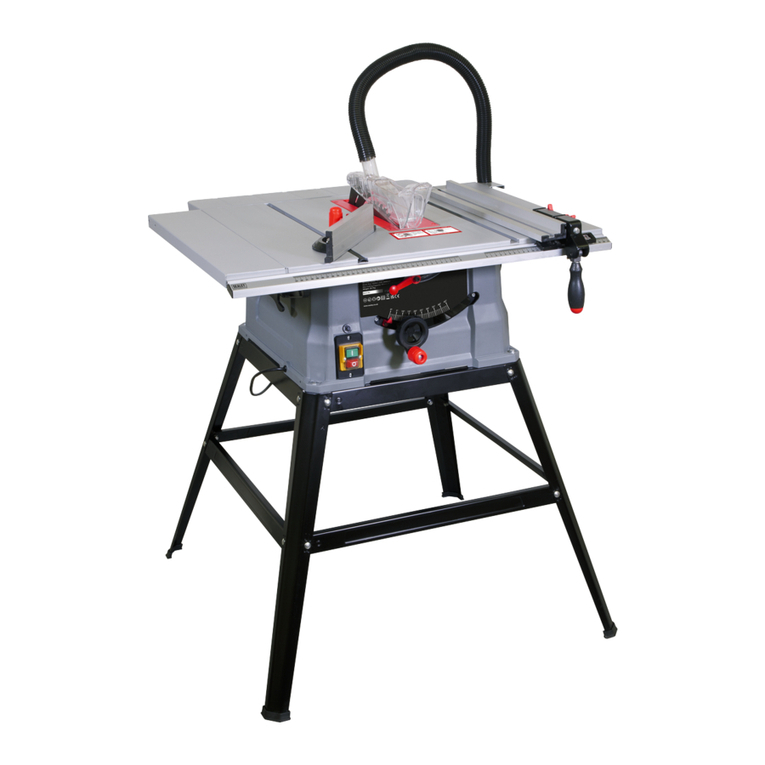
Mac allister COD2000FLS Installation manual

Thank you for purchasing a MacAllister product. We are confident that this product will meet and
exceed your expectations of quality and reliability. Please take the time to carefully read this entire
instruction manual before using your new product, and take note of the basic safety precautions
contained herein.
MacAllister Power Tools,
1 Hampshire Corporate Park, Chandlers Ford,
Eastleigh, Hants S053 3YX
Technical Helpline 0845 300 2577
MacAllister Power Tools,
1 Hampshire Corporate Park, Chandlers Ford,
Eastleigh, Hants S053 3YX
Technical Helpline 0845 300 2577
2000W
FLIP OVER SAW
COD2000FLS
SAFETY AND OPERATING MANUAL
CCaauuttiioonn: Carefully read this entire Instruction Manual before using this product
050707 COD2000FLS ED04
25 2726 28 3029
31 32 33 34 35 36
37 3938 40 4241
43 44 45 46 47 48

A
1 32
BC
4 65
7 8 9 10 11 12
13 1514 16 1817
19 20 21 22 23 24
1
9
4
15
29
10
14
11
3
12
13
7
8
17
15
16
18
19
20
21
22
23
3
24
225 26
27
28
5
6

Contents
1
I - Parts list A/1
II - Technical data 1
III - Safety instructions 2
IV - Getting started 5
V - Operation 7
VI - Maintenance 9
VII - Guarantee 10
I - Parts list II - Technical data
Voltage:...............................230-240V~50Hz
Rated input:.....................................................
.....2000W S6 40% 4min load/6min no load
No load speed:..........................n02800min-1
Blade size:......................Ø250 x Ø30 x3mm
Mitre saw mode
Max cut at 90º:..........................210 x 75mm
Max compound mitre cut at 45º x 45º:.........
....................................................150 x 50mm
Max mitre cut at 90º x 45º:.......150 x 75mm
Max bevel cut at 45º:................210 x 50mm
Table saw mode
Max cut at 90º:.....................................65mm
Max cut at 45º:.....................................45mm
Tilting range:.......................................... 0-45º
Weight:................................................. 53kg
NOISE AND VIBRATION DATA
Aweighted sound pressure:........92.7dB(A)
Aweighted sound power:...........105.7dB(A)
Typical weighted vibration:............3.227m/s2
The sound intensity level for the operator
may exceed 85dB(A) and sound protection
measures are necessary.
1. Saw table
2. Bevel position locking lever
3. No Volts ON/OFF switch
4. Folding workstand
5. Rip fence guide channel
6. Mitre fence guide channel
7. T handle
8. Blade height adjustment knob
(Table saw mode)
9. Motor
10. Mitre saw handle
11. Rotating table
12. Mitre saw fence
13. Retractable blade guard
14. Mitre saw head locking knob
15. Push stick storage point
16. Locking knob
17. Push stick
18. Riving knife locking knob
19. Fixed guard
20. Guard locking lever
21. Blanking plug
22. Belt guard
23. Rotating table lock lever
24. Adjustable foot
25. Table insert
26. Top guard
27. Riving knife
28. Rip fence
29. Mitre gauge
ˇ˝
ˇ˝
ˇ˝
1
23

2
III - Safety instructions
GENERAL SAFETY INSTRUCTIONS
WARNING! Read all instructions. Failure to follow all
instructions listed below may result in electric shock, fire
and/or serious injury. The term "power tool" in all of the
warnings listed below refers to your mains operated (cord-
ed) power tool or battery operated (cordless) power tool.
SAVE THESE INSTRUCTIONS
1) WORK AREA
a) Keep work area clean and well lit.
Cluttered and
dark areas invite accidents.
b) Do not operate power tools in explosive
atmospheres, such as in the presence of
flammable liquids, gases or dust.
Power tools
create sparks which may ignite the dust or fumes.
c) Keep children and bystanders away while
operating a power tool.
Distractions can cause
you to lose control.
2) ELECTRICAL SAFETY
a) Power tool plugs must match the outlet. Never
modify the plug in any way. Do not use any
adaptor plugs with earthed (grounded) power
tools.
Unmodified plugs and matching outlets will
reduce risk of electric shock.
b) Avoid body contact with earthed or grounded
surfaces such as pipes, radiators, ranges and
refrigerators.
There is an increased risk of electric
shock if your body is earthed or grounded.
c) Do not expose power tools to rain or wet
conditions.
Water entering a power tool will
increase the risk of electric shock.
d) Do not abuse the cord. Never use the cord for
carrying, pulling or unplugging the power tool.
Keep cord away from heat, oil, sharp edges or
moving parts.
Damaged or entangled cords
increase the risk of electric shock.
e) When operating a power tool outdoors, use an
extension cord suitable for outdoor use.
Use of
a cord suitable for outdoor use reduces the risk of
electric shock.
3) PERSONAL SAFETY
a) Stay alert, watch what you are doing and use
common sense when operating a power tool.
Do not use a power tool while you are tired or
under the influence of drugs, alcohol or
medication.
A moment of inattention while
operating power tools may result in serious
personal injury.
b) Use safety equipment. Always wear eye
protection.
Safety equipment such as dust mask,
non-skid safety shoes, hard hat, or hearing
protection used for appropriate conditions will
reduce personal injuries.
c) Avoid accidental starting. Ensure the switch is
in the off position before plugging in.
Carrying
power tools with your finger on the switch or
plugging in power tools that have the switch on
invites accidents.
d) Remove any adjusting key or wrench before
turning the power tool on.
A wrench or a key left
attached to a rotating part of the power tool may
result in personal injury.
e) Do not overreach. Keep proper footing and
balance at all times.
This enables better control of
the power tool in unexpected situations.
f) Dress properly. Do not wear loose clothing or
jewellery. Keep your hair, clothing and gloves
away from moving parts.
Loose clothes, jewellery
or long hair can be caught in moving parts.
g) If devices are provided for the connection of
dust extraction and collection facilities, ensure
these are connected and properly used.
Use of
these devices can reduce dust related hazards.
4) POWER TOOL USEAND CARE
a) Do not force the power tool. Use the correct
power tool for your application.
The correct
power tool will do the job better and safer at the rate
for which it was designed.
b) Do not use the power tool if the switch does not
turn it on and off.
Any power tool that cannot be
controlled with the switch is dangerous and must be
repaired.
c) Disconnect the plug from the power source
before making any adjustments, changing
accessories, or storing power tools.
Such
preventive safety measures reduce the risk of
starting the power tool accidentally.
d) Store idle power tools out of the reach of
children and do not allow persons unfamiliar
with the power tool or these instructions to
operate the power tool.
Power tools are
dangerous in the hands of untrained users.
e) Maintain power tools. Check for misalignment
or binding of moving parts, breakage of parts
and any other condition that may affect the
power tools operation. If damaged, have the
power tool repaired before use.
Many accidents
are caused by poorly maintained power tools.
f) Keep cutting tools sharp and clean.
Properly
maintained cutting tools with sharp cutting edges
are less likely to bind and are easier to control.
g) Use the power tool, accessories and tool bits
etc., in accordance with these instructions and
in the manner intended for the particular type of
power tool, taking into account the working
conditions and the work to be performed.
Use
of the power tool for operations different from
intended could result in a hazardous situation.
5) SERVICE
a) Have your power tool serviced by a qualified
repair person using only identical replacement
parts.
This will ensure that the safety of the power
tool is maintained.
3
ADDITIONAL SAFETY RULES FOR FLIP OVER SAWS
WARNING! Rotating Circular Saw Blades are extremely
dangerous and can cause serious injury and amputation.
Always keep fingers and hands at least 6" away from the
blade at all times. Never attempt to retrieve sawn material
until the guard is fully closed and the saw blade has
stopped rotating.
WARNING! Do not remove or attempt to modify the blade
guard in any way.
WARNING! Do not attempt to cut material that is larger
than the maximum cutting capacity of machine.
Some wood and wood type products, especially MDF,
(Medium Density Fibreboard) can produce dust that can
be hazardous to your health. We recommend the use of
an approved facemask with replaceable filters when using
this machine in addition to using the dust extraction facility.
Ensure that power tools are disconnected from the mains
supply when not in use, before servicing, lubricating or
making adjustments and when changing accessories such
as blades.
Do not use blades made from High Speed Steel. Do not
stop the blade by forcing the machine or by using
sideways pressure.Always use the correct type of blade
for the operation to be carried out. Do not use blades that
are deformed or have missing teeth. This is highly
dangerous and could result in a serious accident to the
operator and bystanders as well as damaging the
machine. Only use blades that are recommended by the
supplier and that are in good condition.
Do not use blades that are larger than specified only use
blades that are rated for the machine. The rotational speed
(min-1) shown on the blade should always be HIGHER
than the rotational speed (min-1) of the machine.
Ensure that the directional arrow marked on the blade
corresponds with the rotational direction of the motor. The
teeth of the blade should always point downward as
viewed from the front of the saw.
Do not lock the moving guard in the open position. Ensure
that the movable guards operate freely without jamming.
Ensure that the retraction mechanism of the guard system
operates correctly.
Keep guards in place and in good working order.
With the machine disconnected from the mains supply
check the operation of the guard to ensure that it operates
correctly especially after a mode change.
Lower the saw head so that the blade is in its lowest
position, carefully rotate the blade by hand to ensure that it
is free from obstruction.
Repeat this procedure at all maximum mitre and bevel
positions before commencing operation of the Mitre Saw.
When cutting long work pieces use saw horses or work
benches to support the work piece, ensure that all securing
clamps are tight and check for excessive play.
Always keep the blade securing arbor and collars clean.
Whenever replacing blades ensure that the recessed
surface of the blade collar fits snugly against the surface of
the blade. Ensure that the blade securing bolt is securely
tightened using the wrenches provided. Do not over tighten.
Before commencing any cut allow the blade to reach its full
speed, let it run for a few seconds. If any unusual noise or
vibration is heard STOP the machine immediately,
disconnect from the mains supply and investigate the
cause.
Never try to cut free hand. Always ensure that the work
piece is securely pressed against the back fence and table
support surface.
Ensure that the work piece that is being cut off has
sufficient room to move sideways. Failure to do so may
result in the off cut binding against the blade.
If the work piece cannot be held securely by hand then use
the jig or clamp to hold it in place whilst it is being cut.
Ensure that irregular or round pieces are held securely so
that they are unable to move or twist and pinch the blade.
When in table saw mode always use the push stick to feed
the work piece.
The push stick should be returned to its storage when not
in use.
Never cut more than one piece at a time. Never cut pieces
that are too small to be held securely against the back
fence with the thumb and index finger. Use only blades
that are recommended by the manufacturer.
Do not start the machine with the blade in contact with the
work piece.
Check the work piece for any protruding nails, screw
heads or anything that could damage the blade.
Do not attempt to modify the machine or its accessories in
any way.
Do not use excessive force when feeding the work piece
to the blade. Feeding the work piece gradually will reduce
wear on the machine and blade increasing its efficiency
and operating life.

4
Approved ear protection should be worn when using flip
over saws.
Never try to cut pieces that are larger than the maximum
specified for the machine, it can cause damage to the
blade guard and could cause injury to the operator.
The equipment is intended for use only in premises having
a service current capacity equal to, or greater than 100A
per phase.
Ensure that the machine is fixed to a bench, whenever
possible.
Rebating or grooving should not be carried out unless
suitable guarding, such as a tunnel guard, is fitted as a top
guard.
The saw should not be used for slotting (stopped groove).
During transportation the upper part of the saw blade shall
be covered, for example by the top guard or the saw blade
should be adjusted to the lowest position.
Symbols
The rating plate on your tool may show symbols. These
represent important information about the product or
instructions on its use.
Wear hearing protection.
Wear eye protection.
Wear respiratory protection.
Conforms to relevant
safety standards.
Keep hands clear of rotating blade.
Blade may continue to run for a
period when switched off.
Waste electrical products should not be
disposed of with household waste. Please
recycle where facilities exist. Check with your
Local Authority or retailer for recycling advice.
Read the instruction manual.
Do not clear blade obstructions with hands.
Do not push work pieces through blade with
your hand. ONLY USE supplied push stick.

5
ACCESSORIES
The flip over saw is supplied with the following
accessories:
• Blade guard
• Chip collection case for saw blade
(Mitre saw mode)
• Plastic feet x 4 • Hex key x 4
• Wrench • Mitre guide
• Rip fence • Push stick
CAUTION. Always ensure that the flip over saw is
switched off and the plug is removed from the
power point before making any adjustments.
Please remove the protective cardboard from
under the table before use.
ASSEMBLING THE LEG STAND
Lay the machine on its rear side. Unlock the legs
and open them fully, finally lift the machine into an
upright position.
Compensate for an uneven floor using the
adjusting foot.
Alternatively with the legs folded and the 4 plastic
feet fitted, the machine can be used on a suitable
bench.
FITTING THE ON/OFF SWITCH
Attach the ON/OFF switch to the frame of the flip
over saw and secure with the nuts and bolts
supplied.
To store the push stick on the machine remove
the plastic cap from the push stick storage mount.
Hang the push stick onto the storage mount using
the hole on the push stick handle then replace the
plastic cap.
MITRE SAW MODE
SETTING UP FOR MITRE SAW MODE
Remove the blade guard (if fitted) then using the
blade height adjustment knob fully lower the
blade.
2
3
4
IV - Getting started
1Loosen the riving knife locking knob and relocate
the riving knife in the storage position shown
inPic.8. Raise the saw blade fully using the blade
height adjustment knob.
Attach the chip collection case to the table and
secure in position (using the supplied hex key
press the securing screw inwards, then rotate
90º).
Pull the saw table tilt lock handle out and gently
turn the saw table over, release the saw table tilt
lock handle and ensure the table has locked into
position.
WARNING! When turning the saw table over
there is a risk of crushing. Do not reach between
the saw table and side panels. Hold the saw table
firmly when turning over.
Connect a suitable extraction hose to the dust
extraction outlet on the chip collection case.
To unlock the cutting head ready for operation
apply downward pressure to the handle and rotate
the lock knob in a clockwise direction and allow
the head to rise gently to its upper position.
ADJUSTMENTS REQUIRED BEFORE
USING THE MACHINE
The following adjustments must be made before
operating the saw. This is to ensure accuracy and
safety when in operation.
Warning! Before carrying out any maintenance or
adjustments the machine must be disconnected
from the mains power supply.
BLADE TO TABLE ALIGNMENT
You may need an assistant to help with this
adjustment. Slacken the bevel position locking
lever ensuring that the blade is in the 0° bevel
position (Vertical) to the rotating table.
Squeeze the guard locking lever and lower the
blade into the table slot.
Using a protractor or suitable 90° set square
measure the angle that the blade makes with the
rotating table. Note: The protractor shown is not
supplied. Make sure that the protractor or set
9
10
11
12
13
5
6
7
8
14

6
square does not touch the teeth on the blade as a
false reading may occur due to the thickness of
the tungsten carbide tip.
If adjustment is required proceed as follows.
Locate the adjusting screw and lock nut towards
the rear of the machine. Loosen the lock nut and
rotate the adjusting screw clockwise or
anti-clockwise, to increase or decrease the angle
of the blade. When the blade has been set to 90°
allow the saw to return to the upper position. Hold
the adjusting screw, and tighten the lock nut to
secure the setting. Lower the blade and re-check
the 90° angle on the bevel angle scale, making
fine adjustments if necessary.
NOTE: Check the position of the bevel angle
pointer and set to 0° on the angle scale if
necessary.
BLADE TO FENCE ALIGNMENT
CAUTION: The adjustment can only be made
after the blade has been aligned in the table slot.
The saw blade should be located exactly in the
centre of the blade slot, if it requires adjustment
loosen the nut and adjust the position of the blade
by rotating the adjusting nut Finally retighten the
nut.
Position the rotating table to the 0° position (90° to
the work support fence). Lower the saw head into
the down position. Place a suitable set square or
adjustable protractor against the blade. Carefully
move the set square up to the fence.
The angle should measure 90°.If adjustment is
necessary, loosen the lock nut using the supplied
hex key adjust until the blade is at 90° to the
fence. Re-secure the lock knob and re-check the
angle.
ADJUSTING THE 45° BEVEL STOP
Make sure that the rotating table is set at 0° on the
angle scale. Loosen the bevel position locking
lever located at the rear of the machine. Grip the
handle and move the cutting head assembly over
to the left, the scale should read 45°.
Position a suitable protractor or set square on the
table and measure the angle to the blade. It
15
should be 45° from the vertical position or 135°
from the table. If adjustment is required proceed
as follows:
Locate the adjusting screw and lock nut located
towards the rear of the machine. Loosen the lock
nut, and rotate the adjusting screw clockwise or
anti-clockwise, to increase or decrease the angle
of the blade. When the blade has been set to 45°
allow the cutting head to return to the upper
position. Hold the adjusting screw and tighten the
lock nut to secure the setting. Lower the cutting
head and re-check the 45° angle making a fine
adjustment if necessary. When the correct angle
of 45° is achieved, all that is required is to check
that the pointer aligns with 45° on the scale.
FINAL CHECK
With the machine switched OFF and
disconnected from the mains supply carry out the
following final check.
When all adjustments have been made, set the
machine at each of the maximum settings. Lower
the blade to its lowest position, and rotate the
blade by hand (it is advisable to wear gloves
whilst doing this) and ensure that the blade does
not foul on any part of the machine castings or
guards.
TABLE SAW MODE
WARNING! Before carrying out any maintenance
or adjustments the machine must be
disconnected from the mains power supply.
CONVERTING FROM MITRE SAW TO
TABLE SAW MODE
Set the rotating table to the 0º position then
engage the locking knob and tighten the rotating
table locking lever.
Set the saw head to the vertical 0º position and
tighten the bevel locking lever.
Lower the cutting head assembly downwards until
it stops. Rotate the lock knob in an anti clockwise
direction the cutting head will be locked in the
down position.
Pull the saw table tilt lock handle out and gently
turn the saw table over, release the saw table tilt
lock handle and ensure the table has locked into
position.
WARNING! When turning the saw table over
there is a risk of crushing. Do not reach between
the saw table and side panels. Hold the saw table
firmly when turning over.
16
17
18
19
20
21
22

Remove the chip collection case from the table
(using the supplied hex key press the securing
screw in, then rotate 90º). Using the blade height
adjustment knob fully lower the blade then loosen
the riving knife locking knob and relocate the riving
knife in the position shown in Pic.22. Raise the
saw blade fully using the blade height adjustment
knob.
Fit the blade guard onto the riving knife. With the
blade guard secured in place a suitable extraction
hose can be fitted to the dust extraction outlet.
FITTING THE MITRE GAUGE
The mitre gauge simply locates in the location
groove on the left side of the table and can be
used for cutting at various angles.
To check the accuracy of the mitre gauge, ensure
that the pointer is set to 0° on the angle scale and
perform a cut. Check the angle of the cut if it is not
at 90° adjust the mitre gauge until a 90° cut is
achieved. Check the position of the pointer against
the angle scale and if required adjust the position
of the pointer to 0° by slackening the cross head
pointer securing screw and set the pointer to zero
on the angle scale and re-secure with the cross
head screw.
ASSEMBLING & CONNECTING THE RIP
FENCE
Attach the rip fence onto the rip fence mounting
bracket. Align the two bolts with the two holes in
the rip fence bracket. Insert the bolts through the
holes and secure with washers and nuts provided.
The rip fence can be fitted to either side of the rip
fence mounting bracket.
Carefully offer the rip fence bracket into the guide
channel. Slide the rip fence to the desired position
and lock in place using the locking lever.
RAISING / LOWERING & TILTING THE
BLADE
Locate the blade height adjustment knob at the
front of the saw table. To elevate the blade, rotate
the knob in an anti-clockwise direction.
To lower the blade, rotate the blade height
adjustment knob in a clockwise direction.
This machine is fitted with a blade assembly that
can be tilted to achieve cuts of between 0° & 45°.
To tilt the blade assembly, slacken the bevel
position locking lever and select the angle of cut 7
using the degree scale.
When the desired angle has been set, tighten the
locking lever.
NOTE: The degree scale is a guide only, for
accurate angle cuts we recommend the use of an
adjustable protractor.
MITRE SAW MODE
SWITCHING ON AND OFF
The blade guard covers the blade when the
cutting head is in its uppermost position.
Familiarise yourself with its operation before
starting the motor.
NO VOLTS EMERGENCY STOP SWITCH
This machine is fitted with a “No Volts Switch”. In
the event of a mains power failure or if the mains
plug is removed from the mains supply socket
before the machine is switched off. The machine
will not re-start without warning when the mains
supply is restored or the mains plug is
re-connected to the mains supply, until the
machine is switched ON at the ON/OFF switch
fitted to the machine. The switch is also fitted with
an emergency stop cover. To start the machine, lift
the emergency stop cover and press the green
ON button. To stop the machine, press the red
OFF button. In the event of an emergency, hit the
emergency stop cover, this will switch the machine
OFF and will mechanically lock the emergency
stop cover in place preventing the machine from
being switched on until the mechanical lock has
been released. To release the mechanical lock
depress the emergency button and slide it
upwards.
Turn the On/Off switch On, grip the handle with
your right hand squeeze the guard locking lever
and twist forward. With a gradual smooth action
lower the cutting head assembly downwards until
it stops. Again with a gradual smooth action let the
cutting head assembly raise until it stops, at the
same time release the blade guard locking lever.
NOTE: At the completion of each cut turn the
On/Off switch Off and allow the blade to stop
rotating before raising the cutting head assembly.
WARNING! Do not remove or attempt to modify
the blade guard in any way.
WARNING! Do not attempt to cut material that is
larger than the maximum cutting capacity of
machine.
WARNING! Never attempt to retrieve sawn
material until the guard is fully closed and the
blade has stopped rotating.
23
24
25 & 26
27
28
V - Operation

8
MITRE AND ANGLE CUTS
Loosen the rotating table locking lever then lift up
the locking knob and rotate the table to the
desired angle. Release the locking knob and
re-secure the table locking lever. Start the saw
and make the cut through the material in a
smooth action.
WARNING. Be sure to tighten the table locking
lever before making a cut. Failure to do so could
result in the table moving during the cut, causing
serious personal injury.
BEVEL CUTS
Loosen the bevel locking lever and tilt the saw
head over to the desired angle. Re-secure the
bevel position locking lever. Start the saw and
make the cut through the material in a smooth
action.
WARNING. Be sure to tighten the bevel locking
lever before making a cut. Failure to do so could
result in the saw arm moving during the cut,
causing serious personal injury.
COMPOUND CUTS
Acompound cut is a combination of both mitre
and bevel cuts. Loosen the rotating table locking
lever. Set the desired mitre angle and re-secure
the rotating table locking lever. Loosen the bevel
position locking lever and set the desired bevel
angle. Re-secure the bevel position locking lever.
Start the saw and make the cut through the
material in a smooth action.
WARNING. Be sure to tighten the mitre and bevel
locking levers before making a cut. Failure to do
so could result in the table and/ or saw arm
moving during the cut, causing serious personal
injury.
TABLE SAW MODE
TURNING THE SAW ON & OFF
To start the machine, lift the emergency stop cover
and press the green ON button. To stop the
machine, press the red OFF button. In the event
of an emergency, hit the emergency stop cover,
this will switch the machine OFF and will
mechanically lock the emergency stop cover in
place preventing the machine from being switched
on until the mechanical lock has been released.
To release the mechanical lock depress the
emergency button and slide it upwards.
29, 30 & 31 CROSS CUTTING
Cross cutting is cutting wood across the grain at
90° or square with both the edge and the flat side
of the wood.
MITRE CROSS CUTTING
Mitre cross cutting is cutting the wood at an angle
other than 90° with the edge of the wood. Follow
the same procedures as you would for cross
cutting. But adjust the mitre gauge to the desired
angle.
BEVEL CROSS CUTTING
Bevel cross cutting is the same as cross cutting
except that the wood is also cut at an angle other
than at 90° with the flat side of the wood. Follow
the same procedures as you would for cross
cutting. But adjust the blade to the desired angle.
Use the mitre gauge in the groove to the left of the
blade to avoid the blade guard from interfering
with the cross cutting.
WARNING!
When cross cutting, mitre cutting, bevel cutting
and when rabbeting across the end of a narrow
work piece always use the mitre gauge. NEVER
make these cuts freehand (not using the mitre
gauge or the other devices) because the blade
could bind causing a kickback or causing your
hand or fingers to contact the blade.
ALWAYS lock the mitre gauge when in use.
Remove the rip fence from the table when not in
use.
Make sure the blade safety guard is mounted for
all through sawing operations (the blade cuts
through the entire thickness of the work piece).
The blade should extend approximately 3.5mm
(1/8”) above the top of the work piece.
COMPOUND MITRE CUTTING
Compound mitre cutting is a combination of mitre
cutting and bevel cross cutting.
The cut is made at an angle other than 90° to both
the edge and the flat side of the wood.
Adjust the mitre gauge and the blade to the
desired angle and be sure that the mitre gauge is
locked.
REPETITIVE CUTTING
Repetitive cutting is cutting a number of pieces the
same length, without having to mark each piece.
32
33
34
35
36
37
38
39

The safe way to perform repetitive cutting, is to set
the rip fence to give the required length, and to be
clear of the front of the blade. When the cut is
made, the end of the work piece is clear of the rip
fence but at the required length.
NEVER use the rip fence as a length stop
because the cut off piece could bind between the
fence and the blade causing a kickback.
RIPPING
Ripping is cutting a piece of wood with the grain or
length wise.
This is done using the rip fence. Position the rip
fence to the desired width of the rip and lock it in
place. Before starting to rip, be sure that the rip
fence is parallel to the saw blade, and that the
riving knife is properly aligned with the saw blade.
When ripping long boards or large panels always
use a work support. Hold the piece against the
fence and feed it through the blade with a smooth,
steady pressure.
When the ripping width is wider than 150mm (6”)
use your right hand to feed the work piece until it
is clear of the table. Use your left hand only to
guide, not to feed the work piece.
REPLACING THE BLADE
WARNING! Before carrying out any maintenance
or adjustments the machine must be
disconnected from the mains power supply.
Always wear sturdy gloves when handling or
changing blades as they can be very sharp.
WARNING! Never try to modify the motor spindle
to accept any other size blades or remove any of
the guarding. With the machine switched OFF and
disconnected from the mains supply place the
machine in Mitre saw mode. Release the mitre
saw head locking knob and allow the machine to
rise upwards with the guard in its closed position.
Remove the plastic plug on the belt guard and
hold the saw spindle with the hex key supplied.
Loosen the blade bolt (Important: lefthand thread.
Unscrew clockwise) with the hex key supplied
followed by the blade securing flange
Lower the mitre saw head and lock in position.
Remove the saw blade from below the table.
Refitting is a reversal of removal.
Check that the guard operates correctly by
lowering and raising the cutting head assembly. 9
Re-check all adjustments and settings periodically
for accuracy.
WARNING: It is important that the blade guard is
fitted and operates correctly.
DRIVE BELT REPLACEMENT/
TENSIONING
Before carrying out any maintenance or
adjustments the machine must be disconnected
from the mains power supply.
NOTE: Replacement drive belts can be obtained
from your customer service centre.
To replace the drive belt remove the belt guard.
Loosen the 4 motor screws 1 turn.
Remove the belt from the 2 pulleys. Fit the new
belt ensuring that all the grooves in the belt are
correctly located into the grooves in the pulley.
To tension the belt, push the motor over to the
right and retighten the 4 motor screws.
To check that the correct tension has been
achieved, press your finger onto the centre of the
drive belt the drive belt should move
approximately 5mm.
Re-fit the belt guard. Switch the machine on and
allow it to reach full speed. If it vibrates abnormally
or makes an unfamiliar sound stop immediately
and investigate the cause.
TABLE INSERT REPLACEMENT
With the machine in table saw mode remove the
blade guard and lower the saw blade fully.
Remove the table insert and replace with a new
one.
GENERAL INSPECTION
Regularly check that all the fixing screws are tight.
They may vibrate loose over time.
If the supply cord requires replacing, the task must
be carried out by the manufacturer, the
manufacturers agent, or an authorised service
centre to avoid a safety hazard.
40 & 41
VI - Maintenance
42
43
44
45
46
47

10
PLUG REPLACEMENT
If you need to replace the fitted plug then follow
the instructions below.
IMPORTANT. The wires in the mains lead are
coloured in accordance with the following code:
Blue – Neutral
Brown – Live
Yellow / Green - Earth
As the colours of wires in the mains cable of this
appliance may not correspond with the coloured
markings identifying the terminals in your plug,
proceed as follows.The blue wire must be
connected to the terminal which is marked with N
or coloured black. The brown wire must be
connected to the terminal which is marked with an
L or coloured red. Connect the Green and Yellow
wire to the terminal marked Earth E
WARNING. Never connect live or neutral wires to
the earth terminal of the plug.
Only fit an approved 13 Amp BS1363/Aplug and
the correct rated fuse.
NOTE. If a moulded plug is fitted and has to be
removed take great care in disposing of the
plug and severed cable, it must be destroyed to
prevent engaging into a socket.
Thank you for investing in MacAllister.
These products have been made to demanding,
high quality standards and are guaranteed for
domestic use against manufacturing faults for a
period of 36 months from the date of purchase.
To take advantage of this free extended warranty
please register on www.diy.com or by phoning the
Technical Helpline on 0845 300 2577.
This guarantee does not affect your statutory
rights.
If your product fails due to a defect in material or
workmanship during this period, please return it to
your nearest B&Q store.
Normal wear and tear, including accessory wear,
is not covered under guarantee.
The product is guaranteed for 12 months if used
for normal trade purposes. Any guarantee is
invalid if the product has been overloaded or
subject to neglect, improper use or an attempted
repair other than by an authorised agent. Heavy
duty, daily professional or hire usage are not
guaranteed.
Due to continuous product improvement, we
reserve the right to change the product specifica-
tion without prior notice.
VII - Guarantee
48
Other Mac allister Saw manuals

Mac allister
Mac allister MSPS1200 Installation instructions

Mac allister
Mac allister MSSP120 User manual

Mac allister
Mac allister 64 77 19 User manual

Mac allister
Mac allister MSTS1500-A User manual

Mac allister
Mac allister MGSP18LI User manual

Mac allister
Mac allister MJ10250XI Guide

Mac allister
Mac allister MTSP800A User manual
Popular Saw manuals by other brands

Delta
Delta 36-725 T2 instruction manual

EGAmaster
EGAmaster 79658 operating instructions

Delta
Delta 33-890 instruction manual

Z.I.P.P.ER MASCHINEN
Z.I.P.P.ER MASCHINEN ZI-FKS250 Operation manual

MEISTER CRAFT
MEISTER CRAFT MKR 1400 L Translation of the original instructions

Delta
Delta Homecraft PM-1694 Operating and maintenance instructions