Mac Medical DWC24-TL User manual

1
INSTALLATION INSTRUCTIONS: Replacing a Standard Warmer
Header (DWC24-TL) with a Data Log Header (DWC24-TL-D)
IFU - 033 Rev.A 02/23/2015
A: Removing Standard Warmer Cabinet Header
(p/n: DWC24-TL)
The Standard Warmer Header for a DWC24-TL
Dual Warmer Cabinet can be easily replaced
with a DWC24-TD-D Warmer Cabinet Header
with a Data Logger option.
1. Disconnect all electrical power to the Warming
Cabinet by removing the power cord from the
electrical supply. If the unit is hard-wired to
facility power, turn OFF the circuit breaker.
CAUTION:
Failure to remove the power cord from
the electrical supply can result in severe
electrical shock and even death to
personnel as well as severe damage to
the equipment.
2. The Outside and Inside Top Panels must be
removed first. See Figure 1.
3. Remove four 8 X 1-5/8” self-tapping screws
from Outside Top Panel. Remove Outside
Top Panel and set aside. See Figure 1.
4. Remove two 8 X 1/2” self-tapping screws from
Inside Top Panel. Remove Inside Top Panel
and set aside. See Figure 1.
The Standard Warmer Header for a DWC24-TL
Dual Warmer Cabinet can be removed from a
standard dual warming cabinet without removing
the Upper Drawer Assembly (p/n: W0288).
1. There is no specific order in removing all
wiring to the Header, just specific steps that
allows the wiring to pass safely through the
electrical box.
2. Loosen two screws on the 3/8” straight-
through electrical connector mounted on the
back side of the Warmer Cabinet Electrical
Box (just behind the Header). See Figure 2.
3. Use a Pin Extraction Tool (for 16AWG wire) to
remove the wire leads from the 9-/5-Connector
Circuit Plugs. See Figure 3.
CAUTION: Use ONLY a Pin Extraction Tool
designed for the specific wire size
REF P/N DESCRIPTION QTY
1 SMW0027 Outside Top Panel 1
2 SMW0028 Inside Top Panel 1
3 H0012-01 Screw, Self-Tapping, 8 X 1/2” 2
4 H0012-02 Screw, Self-Tapping, 8 X 1-5/8” 4
Figure 1: Removing Inside and Outside Top Panel
12
3
4
REF P/N DESCRIPTION QTY
1 W0199 Connector, 9 Circuit Plug 1
2 W0198 Connector, 5 Circuit Plug 1
3 SMW0032 Cover, Electrical Box 1
4 W0140 Connector, 3/8” Straight 1
REF P/N DESCRIPTION QTY
1 16AWG Tool, Pin Extraction 1
2 W0198 Connector, 5 Circuit Plug 1
3 16AWG Wire, Crimped Terminal End 1
Figure 2: Loosening Wire Connector on Electrical Box
12 34
Figure 3: Removing Wires from Circuit Plug
1
2
3

2
INSTALLATION INSTRUCTIONS: Replacing a Standard Warmer
Header (DWC24-TL) with a Data Log Header (DWC24-TL-D)
IFU - 033 Rev.A 02/23/2015
used. DO NOT attempt to push the
wire terminal out of the connector
with a small Phillips screwdriver or
similar tool. This method will
damage both the connector and
wire resulting in replacement.
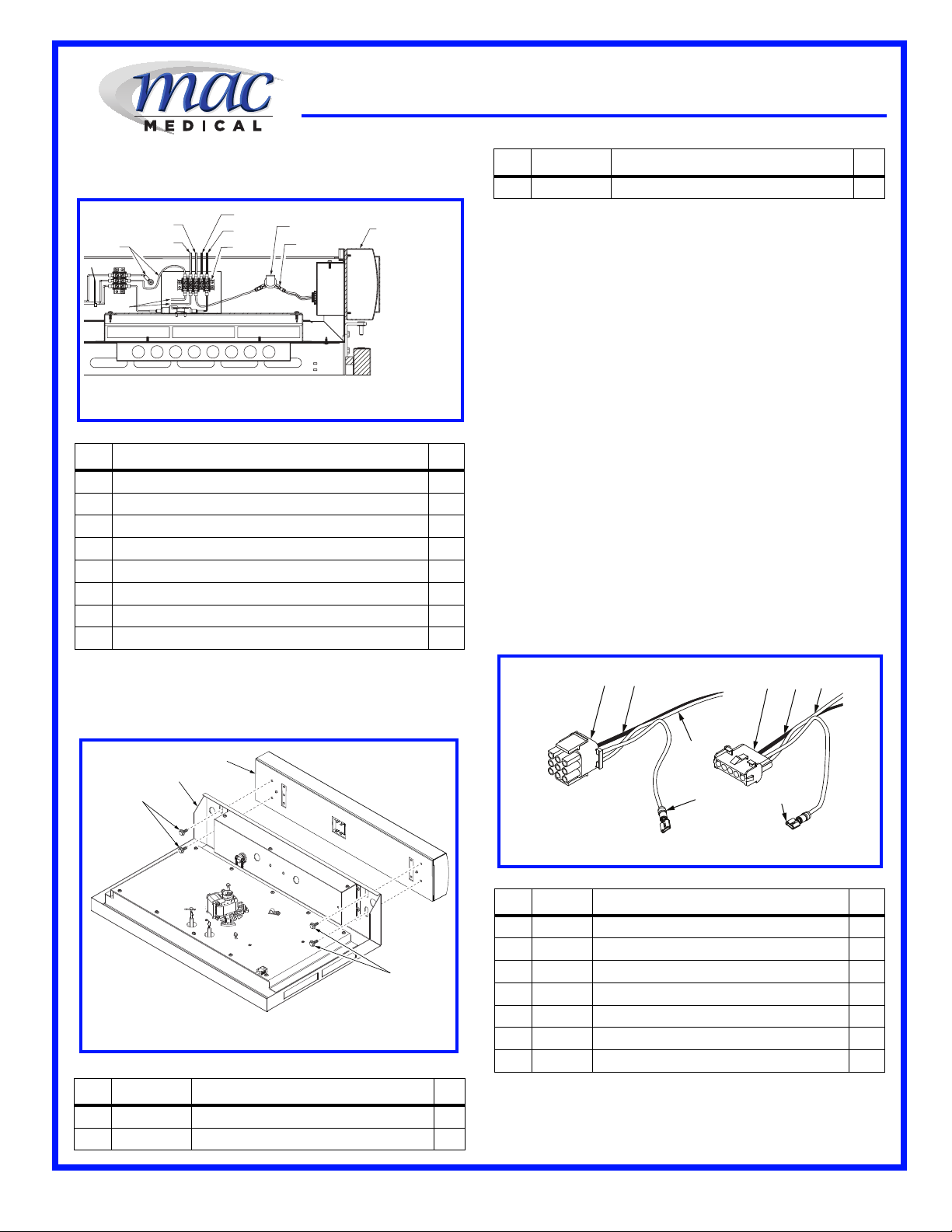
4. There are two molded connectors used. A 9-
pin is used for the Lower Warmer connection
and a 5-pin is used for the Upper Warmer
connection. It is recommended that before
disconnecting the wires, each set should be
taped together and marked to prevent placing
the wrong wire in a connector. See Figure 4.
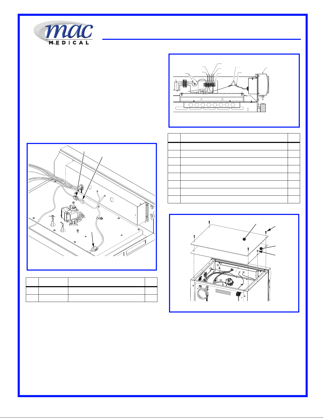
5. There are two (an upper and lower) Thermo-
couple connections that feeds data to the
header from the upper and lower warmer
units. These Thermocouple connectors are
located in the upper drawer of the Warming
Cabinet.
6. When exchanging the header, each Thermo-
couple connector must be disconnected. See
Figure 5, Items 1 through 2. Items 1 (p/n:
W0037) is a male connection and does not go
through the Header and does not need to be
taken apart. Item number 2, is a female
receptacle, (p/n: W0038) and must have the
wires removed before the header can be
removed.
7. Remove the two screws on one female
receptacle and one male receptacle and lift off
the cover. See Figure 5, Items 2 and 3. Place
the screws and cover in an area where they
will not be misplaced. Loosen the two screws
on the inside and pull the two wires away from
the receptacle.
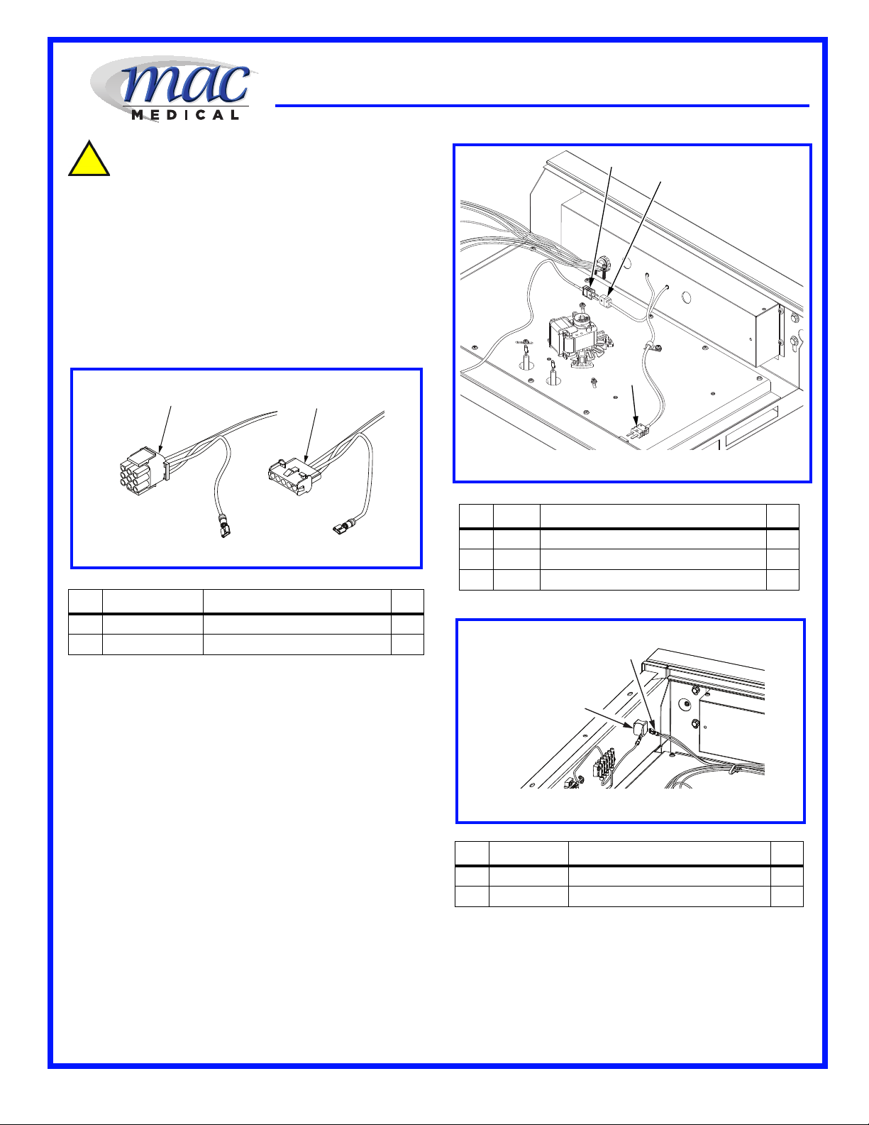
8. The only remaining wires to disconnect are the
lead to the Over Temperature Alarm Buzzer
and the power leads to the 5-Position Terminal
block on the cabinet side wall. See Figure 7.
9. The Over Temperature Alarm Buzzer lead pulls
directly off the buzzer and out through the
Electrical Box behind the Header. The
connector will consist of two wires in the
REF P/N DESCRIPTION QTY
1 W0199 Connector, 9 Circuit Plug 1
2 W0198 Connector, 5 Circuit Plug 1
Figure 4: Molded Power Connectors
1
2
REF P/N DESCRIPTION QTY
1 W0037 Connector, Male, Upper Chamber 2
2 W0038 Connector, Female, Upper Chamber 1
3 W0037 Connector, Male Lower Chamber 1
REF P/N DESCRIPTION QTY
1 W0013 Buzzer, Over Temperature Alarm 1
2 W0118 Terminal, Over Temperature Alarm 1
Figure 5: Disconnecting Thermocouple Connectors
1
3
2
Figure 6: Over Temperature Alarm Buzzer
1
2

3
INSTALLATION INSTRUCTIONS: Replacing a Standard Warmer
Header (DWC24-TL) with a Data Log Header (DWC24-TL-D)
IFU - 033 Rev.A 02/23/2015
Warmer Unit is a dual cabinet and a single
wire if the Warmer Unit is a single cabinet.
10. Remove the four 1/4”-20X1/2” serrated
flange head bolts and remove the existing
Header from the Warming Cabinet.
11. Carefully pull the Header away from the
Warming Cabinet while making sure none of
the existing wiring gets caught on the cabinet
structure. See Figure 8.
B: Installing USB Data Log Header (p/n:
DWC24-TL-D) on Existing Warming Cabinet
1. Feed wiring from new USB Header through
openings in cabinet electrical box attached to
the Upper Tray. Replace the four 1/4”-20X1/2”
serrated flange head bolts and remove the
existing Header from the Warming Cabinet. See
Figure 8.
2. Connect lower lead for the
Over Temperature
Alarm Buzzer (See Figure 7, Item 7) if unit is a
dual cabinet warmer model Connect the wire/s
to the Buzzer. See Figure 6.
3. Insert the barbed connector wires (one black
and one white) into the Lower Cabinet 9-
Position Molded Plug (See Figure 9, Item 1).
Reconnect the two halves of the plug. Make
sure the wire colors match once the plug is
reconnected.
4. Insert the barbed connector wires (one black
and one red) into the Upper Cabinet Connector
REF DESCRIPTION QTY
1 Power Cable Ground Wires (W) 1
2 To Lower Chamber Control Board (W) 1
3 To Upper Chamber Control Board (W) 1
4 To Lower Chamber Control Board (B) 1
5 To Upper Chamber Control Board (B) 1
6 W0006 5-Position terminal Block 1
7 Alarm Hookup (2 wires if Dual Chamber) (Orange) 1
8 To Upper and Lower Coils (W) 2
REF P/N DESCRIPTION QTY
1 H0016-10
Bolt, Serrated Flange Head, 1/4”-20-1/2”
4
2 W0288 Upper Drawer Assembly 1
Figure 7: Un-wiring Terminal Block
1
8
2
34
5
6
ALARM
7
HEADER
Figure 8: Removing Existing Cabinet Header
1
1
2
3
3DWC24-TL
Header Assembly without USB Data Log
1
REF P/N DESCRIPTION QTY
1 W0199 Lower Molded Connector 1
2 Lower Chamber Power Wire (Black) 1
3 Lower Chamber Common Wire (White) 1
4 W0198 Upper Molded Connector 1
5 Upper Chamber Power Wire (Black) 1
6 Upper Chamber Common Wire (White) 1
7 Ground Connections 2
REF P/N DESCRIPTION QTY
12
3
45
77
6
Figure 9: Reconnecting Molded Connectors

4
INSTALLATION INSTRUCTIONS: Replacing a Standard Warmer
Header (DWC24-TL) with a Data Log Header (DWC24-TL-D)
IFU - 033 Rev.A 02/23/2015
(p/n: W0198) and Lower Cabinet Connector
(p/n: W0199) (See Figure 9, Items 1 and 4).
Reconnect the two halves of each plug making
sure the wire colors match on both sides.
5. Wrap the two leads around the posts inside the
thermocouple receptacle and replace the cover.
Install the two screws holding the cover
together.
6. Connect both the male and female thermo-
couple connectors (See Figure 10, Items 1
and 2) for the upper chamber.
7. Connect the male thermocouple to the stationary
connector on the back side of the drawer for the
lower chamber. See Figure 10, Item 3.
9. Connect the remaining leads from the two
power bundles (to the W0198 and W0199
connectors) from the Electrical Box located
behind the Header. See Figure 11.
10. Once the wires from the two bundles are
connected, separate the wires into two
groups. One group goes to the Upper Cabinet
and the other group goes to the Lower
Cabinet. Use a cable tie to secure and
separate each of the two bundles.
Re-install the Outside and Inside Top Covers
1. Install the Inside Top Panel using two 8 X 1/2”
inch screws to the cabinet. See Figure 12,
Item 4).
2. Use four 8 X 1-5/8” self-tapping screws to
secure to the Outside Top Panel to the
cabinet. See Figure 12, Item 2.
REF P/N DESCRIPTION QTY
1 W0037 Connector, Male Thermocouple 2
2 W0038 Connector, Female Thermocouple 2
Figure 10: Connecting Thermocouple Connectors
1
3
2
REF DESCRIPTION QTY
1 Power Cable Ground Wires (W) 1
2 To Lower Chamber Control Board (W) 1
3 To Upper Chamber Control Board (W) 1
4 To Lower Chamber Control Board (B) 1
5 To Upper Chamber Control Board (B) 1
6 W0006 5-Position terminal Block 1
7 Alarm Hookup (2 wires if Dual Chamber) (Orange) 1
8 To Upper and Lower Coils (W) 2
1
8
2
34
5
6
ALARM
7
HEADER
Figure 11: Installing Wiring on the Terminal Block
Figure 12: Installing Inside and Outside Top Panels
12
3
4
This manual suits for next models
1
Popular Food Warmer manuals by other brands

Alto-Shaam
Alto-Shaam HFM-30 Specifications

Chef-Master
Chef-Master HED240 instruction manual

mr. steam
mr. steam W500 Installation & operating instructions

Alto-Shaam
Alto-Shaam 1000-UP Specification sheet

Alto-Shaam
Alto-Shaam 100-HW/D4 Installation, operation and maintenance instructions

Alto-Shaam
Alto-Shaam Heated Display Systems PD2SYS-72 Specifications