manuals.online logo
Brands
  1. Home
  2. •
  3. Brands
  4. •
  5. Macally
  6. •
  7. Enclosure
  8. •
  9. Macally G-S350SUAB User manual

Macally G-S350SUAB User manual

Other Macally Enclosure manuals

Macally G-S350SU3 User manual

Macally

Macally G-S350SU3 User manual

Macally NSA2-S350U User manual

Macally

Macally NSA2-S350U User manual

Macally G-S350SUAB2 User manual

Macally

Macally G-S350SUAB2 User manual

Macally PHR-250CE User manual

Macally

Macally PHR-250CE User manual

Macally PHR-S250U3B User manual

Macally

Macally PHR-S250U3B User manual

Macally NSA2-S350U User manual

Macally

Macally NSA2-S350U User manual

Popular Enclosure manuals by other brands

Antec Veris Fusion Remote Max Specification sheet

Antec

Antec Veris Fusion Remote Max Specification sheet

ENERMAX iVektor.Q ECA 3371 Series user manual

ENERMAX

ENERMAX iVektor.Q ECA 3371 Series user manual

Lindy 43095 user manual

Lindy

Lindy 43095 user manual

SICK C4000 Select operating instructions

SICK

SICK C4000 Select operating instructions

Geeek A60 PLUS installation guide

Geeek

Geeek A60 PLUS installation guide

OVE SYDNEY 48 installation manual

OVE

OVE SYDNEY 48 installation manual

SilentiumPC Armis AR5 Hardware installation

SilentiumPC

SilentiumPC Armis AR5 Hardware installation

Pulsar 17/TRP80/DSPR Assembly instructions

Pulsar

Pulsar 17/TRP80/DSPR Assembly instructions

MSI MPG SEKIRA 500X quick start guide

MSI

MSI MPG SEKIRA 500X quick start guide

Antec Dark fleet DF-10 user manual

Antec

Antec Dark fleet DF-10 user manual

Peavey DS 1502 Specifications

Peavey

Peavey DS 1502 Specifications

D-Link ShareCenter Pro DNS-1550-04 user manual

D-Link

D-Link ShareCenter Pro DNS-1550-04 user manual

Rosewill RX82-U(JBOD) user manual

Rosewill

Rosewill RX82-U(JBOD) user manual

QNAP SAS JBOD CLI 1.0 user guide

QNAP

QNAP SAS JBOD CLI 1.0 user guide

GAMDIAS Talos P1 Quick installation guide

GAMDIAS

GAMDIAS Talos P1 Quick installation guide

Auvs KR615 user manual

Auvs

Auvs KR615 user manual

Antec AR300 user manual

Antec

Antec AR300 user manual

CommScope FDH 3000 user manual

CommScope

CommScope FDH 3000 user manual

manuals.online logo
manuals.online logoBrands
  • About & Mission
  • Contact us
  • Privacy Policy
  • Terms and Conditions

Copyright 2025 Manuals.Online. All Rights Reserved.

IEEE1394A/IEEE1394B FireWire/Hi-Speed USB2.0/eSATA
3.5” Serial ATA Hard Drive Enclosure
G-S350SUAB
User's Manual
3
Introducing IEEE1394A/IEEE1394B FireWire/Hi-Speed
USB2.0/eSATA
3.5" Hard Drive Enclosure - G-S350SUAB
Thank you for choosing the G-S350SUAB aluminum
IEEE1394A/IEEE1394B FireWire/
Hi-Speed USB2.0/eSATA 3.5" Hard Drive Enclosure. This Aluminum
enclosure supports 3.5” SATA Hard drive up to 1TB. It is simple to install
and comes with all the parts you need to create an external hard drive.
Based on IEEE1394A/IEEE1394B FireWire/SATA II, SATA I, USB2.0 and
USB1.1
specifications the transfer rates are up to:
SATA II - 3.0Gb/s
SATA I - 1.5Gb/s
1394A - 400Mb/s
1394B - 800Mb/s
USB2.0 - 480Mb/s
USB1.1 - 12Mb/s
G-S350SUAB can support the speed specification listed above, however
its
transfer rates are possible to be lower, and will vary depending upon the
Operating System, type of SATA, 1394A,1394B and USB host controller,
SATA Hard Drive and computer hardware.
About This Guide
Before you begin using the G-S350SUAB, be sure to read this manual in
its entirety.
This guide contains:
Introducing IEEE1394A/IEEE1394B FireWire/Hi-Speed
USB2.0/eSATA
3.5" Hard Drive Enclosure
Hardware Installation
Software Installation
Hard Drive Partition and Format in PC Windows 2000/XP/Vista
! FAQ
System Requirements
MacOS 9.2 and MacOS X 10.1 to 10.5 for USB and Firewire connection
! MacOS X 10.2 to 10.5 for SATA connection
!
!
!
!
!
!
Package Contents
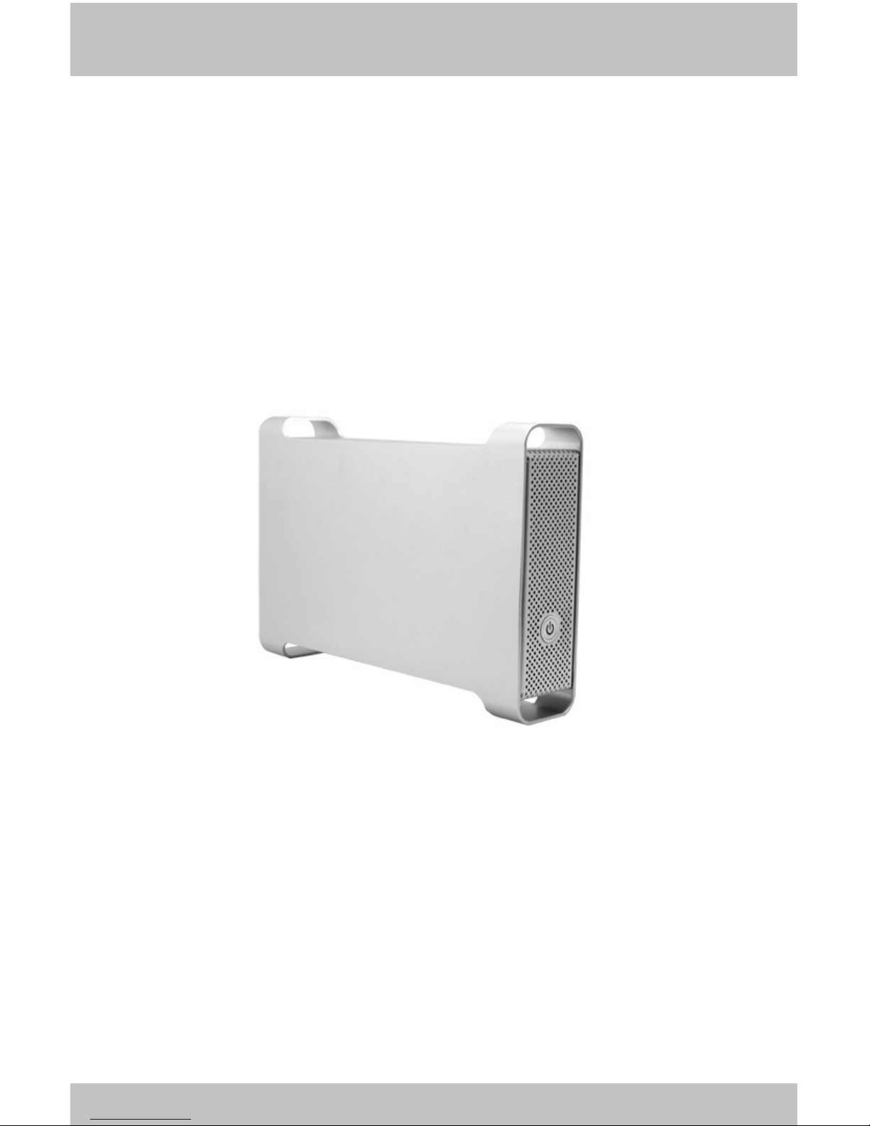
The G-S350SUAB-Aluminum IEEE1394A/IEEE1394B FireWire/Hi-Speed
USB2.0 /eSATA 3.5" Hard Drive Enclosure package includes the
following software and documentation:
G-S350SUAB enclosure
9 pin-9 pin1394B FireWire Cable
USB2.0 cable
Software CD containing the drivers and manual
AC/DC Adapter
eSATA cable(optional)
Safety Precautions
ON INSTALLATION
1. To reduce the risk of fire or electric shock, do not expose this
product to rain, water or moisture.
2. Do not place any containers with liquids (drinking glass, flower
vase, etc.) or containers with small metal parts (paper clips, etc.)
on top of the unit.
3. According to standard industry practice, surge protection is
recommended for all telecommunications devices. Surge suppressors
and/or line conditioning should be used on the input power supply.
ON OPERATION
Do not move the chassis during operation. Doing so may cause a
malfunction.
Protect the unit from shocks and vibrations.
Do not use the subsystem in areas exposed to oily smoke or
steam,such as a kitchen or close to a humidifier.
Do not use the subsystem in locations exposed to rain or splashes of
water, such as outdoors, in a bathroom, or close to a window.
Do not use the subsystem on an unstable or slanted surface without
proper support.
Do not expose the unit to direct sunlight or hot air where the
temperature could exceed 45ºC, or very cold locations where the
temperature is below 0ºC.
Keep the power cord away from hot appliances.
Do not touch the power cord with wet hands.
!
!
!
!
!
!
!
!
!
!
!
!
!
!
4
5
ON TRANSPORTATION
Save the packing materials as you may need to repack and transport the
unit at a later date.
Always remove the disc before moving the unit.
ON POWER SOURCES
When you are not using the unit for a long time, disconnect the power
cord from the unit.
To unplug the AC power adapter from the wall outlet, grasp the adapter
itself. Do not pull the cord.
Warning
If any of the following conditions occur, immediately disconnect the
power cord from the wall outlet and contact your dealer or an authorized
service station. Continuing to use the computer involves the risk of fire
and electric shock.
Smoke or unusual smell is coming from the subsystem.
Water has entered the unit, or the unit has become wet.
A foreign object has entered the unit.
The unit has been dropped or the front panel or frame has been
damaged.
The power cable is damaged, causing wire breakage or exposed
leads.
!
!
!
!
!
Hardware Basic
Precaution:
Please make sure your hand is dry and remove static from your body by
touching metal parts of your computer chassis.
6
1 — Back Panel 2 — 2 -6mm Screws 3 --- Enclosure Sleeve
4 — Base Tray bridge 5 — 6 -5mm Screws 6 — 8 -4mm Screws
7 — Front Panel 8 — Base Tray 9 — Power on/off button
7
Hardware Installation
Note: The diagrams below uses the G-S350U Enclosure as an example.
1. Unscrew to loosen the Enclosure Back Panel. Remove the Back Panel.
2. Use your fingers to push the Base Tray out.
8
3. Pull the Enclosure Sleeve out from the Base Tray and place it aside.
4. Align the black Power/SATA connector on the hard drive to the black
female SATA connector on the Base plate bridge, and push the drive into
the connector completely.
5. Secure the HDD to the Base Tray with 2 hard drive screws.
9
Front Sleeve
6. Push the Base Tray into the Enclosure Sleeve.
7. Secure the Base Tray and Enclosure Sleeve with two 6mm screws.
8. Plug the AC/DC adapter into the Enclosure, and connect the unit to your
computer using a USB cable ,Firewire cable or eSATA cable. Then press
the Power Button to turn it on.