8. Safety
1. Installation should be undertaken by properly trained sta
2.SupplyvoltageshouldNEVERexceedamaximumof24VDC
3. Make sure the sensor is chemically compatible with your
application
4. Design a fail-safe system that accommodates the possibility of
sensorand/orpowerfailure.
5.Thissensorshouldnotbeusedinclassiedhazardous
environments
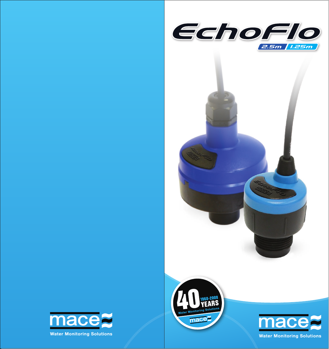
The Slope and Oset values of the installed EchoFlo are dependent
on the “Fill Height”asenteredduringtheEchoCalconguration
procedure.
NOTE: The following calculations are based on the EchoFlo
being congured with a frequency output.
Manually calculating Slope
Slope = Fill Height ÷ Sensor Span
Sensor Span: Is the dierence between the sensor output at the top
of the “Fill Height”(2000Hz)and the sensor output at the bottom
(976Hz).ThefrequencyoutputofanEchoFlohasaspan
of1024Hz.
Manually calculating Oset
Oset=-(SlopexSensoroutputatzero)
Metric example - you wish to calculate the slope and oset for an
EchoFlothathasbeenconguredwitha“Fill Height” of 0.75m (75cm).
Thefollowingcalculationswillprovidethesensor’sslopeandoset:
Slope = 0.75 ÷ (2000-976)
= 0.75 ÷ 1024
= 0.00073
Oset = - (0.00073 x 976)
= - 0.71484
US example - you wish to calculate the slope and oset for an EchoFlo
thathasbeenconguredwitha“Fill Height” of 30”.
Thefollowingcalculationswillprovidethesensor’sslopeandoset:
Slope = 30 ÷ (2000-976)
= 30 ÷ 1024
= 0.02929
Oset = - (0.02929 x 976)
= - 28.59375
NOTE: Be sure to record the relevant “Slope” and“Oset”
values.
Calculating the EchoFlo Slope & Offset
The “Oset adjust” functionisusedtonetunethedepthreading
whenever the sensor is deployed.
1.Click“Oset adjust” from the
“Edit channel” dialogue box and the
“Channel oset adjust” dialogue box
appears. The “Current value” from the
sensor is displayed at the top of the
window and is updated approximately
once per second.
2. To adjust the “Current value”, enter your current measured value
in the “Corrected value” eld.
3.Clickonthe“Apply” button to calculate the new “Oset”
parametervaluefortheassociatedchannel.Clickingonthe“Cancel”
button terminates the procedure without altering the oset value.
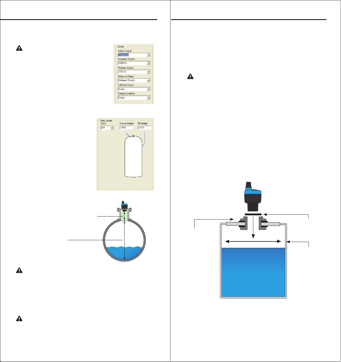
WARNING: When calibrating a depth channel, measurements
should ALWAYS be carried out from the BOTTOM of the
channel/pipe to the top of the water level
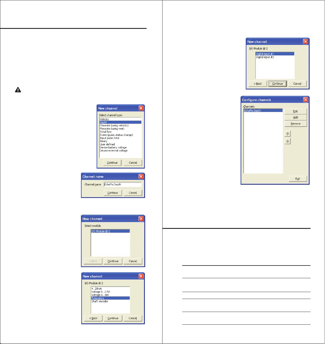
1. In the “Congure
channels” dialogue box
click “Edit” and the “Edit
channel” dialogue box will
appear. Enter the relevant
“Slope” and “Oset” values
as determined using the
previous calculations.
Alternatively, Table 1 lists
thevaluesforEchoFlo’s
conguredwiththeirfull
eective sensor range.
Entering Slope and Offset
Fine tuning the EchoFlo depth reading
WARNING: Be sure to enter the correct values for the selected
depth units