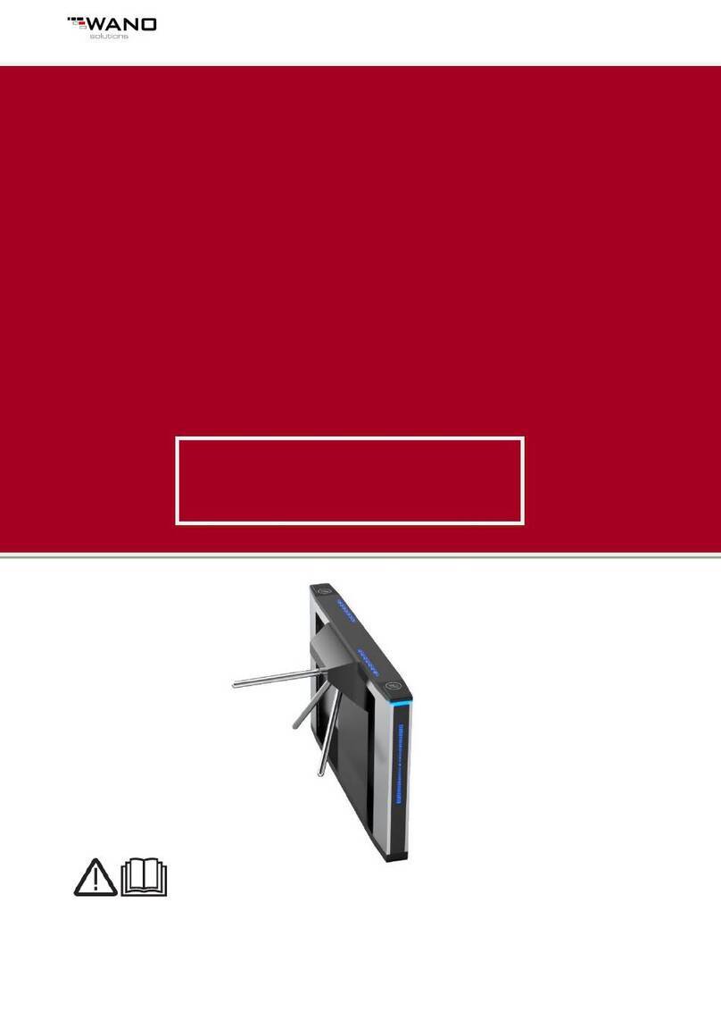
MachPower AC-ATRI-018 User manual

User Manual
TRIPOD AUTOMATIC TURNSTILE
EN
Manuale d'uso
TORNELLO AUTOMATICO TRIPOD
ITA
Manual de usuario
TORNIQUETE AUTOMÁTICO DE TRÍPODE
ES
AC-ATRI-018

2

ENG
3
Index
Product introduction
Installation instruction
Debugging instruction
Attachment I
Attachment II
Wiring diagram
4
5
8
10
12
14

4
Product introduction
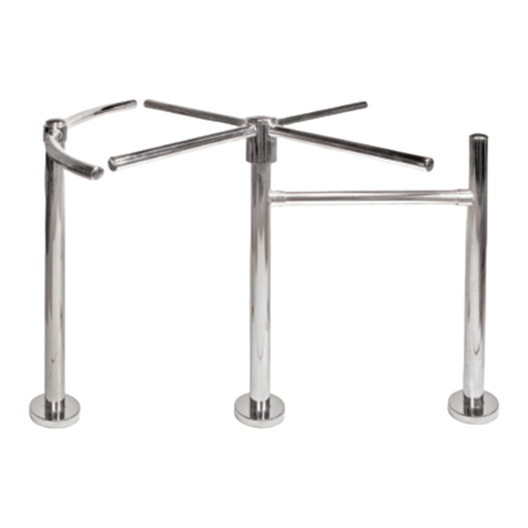
Bridge-type tripod turnstile
Vertical tripod turnstile
Structure Framework/stainless steel shell
Production process Laser cutting fully controlled by computer
Size bridge-type: 1200(L) x 280(W) x 980(H)mm
vertical: 480(L) x 330(W) x 980(H)mm
Weight bridge-type: 70kg
vertical: 45kg
Length of the pole 500(mm)
Max bearing capability of pole 80Kg
Driving force of the pole 3kg
Transmission of the pole digital transmission
The direction of rotation ingle direction, bi-direction(optional)
Light indicator direction indicating
The core of mechanism 24V/30W DC brushless motor , made in Chi-
na, German technology applied
Optical working theory No requirement of prolong-time for the
input control signal
Control panel with counting function and LED digit di-
splay function
Working environment Indoor, outdoor
Temperature -20°C ~ 50°C
Humidity <95%
Emergency Automatically drop the pole
Induction card reader window with standard mounting bracket, or cu-
stom-built
Barrier opening time 0.2sec
Transit speed 30-40 persons/min
Input interface
Dry contact signal or + 12V level signal or
DC12V pulse signal with width of more than
100ms, driving current: > 10mA
Standard RS485 interface being able to connect with management
center directly to fulfill remote control

5
ENG
Users include
Park, tourist attraction, exhibition, sports
center, enterprise and institution, and other
special places
Installation instruction
1. Installation on the ground
First of all, concrete base foot of 200mm height for anti-humidity, (Safe island)
should be built. Then, 220V 3 x 1.5mm power cable and 4 x 0.5mm control cable
tube should be laid under the middle of the casework. Fix turnstile gate in safe
island by screw. Connect turnstile with 220V power and control room
330
100
330
510
720
428
365
251
100
35
428
980
Ø18
4 x M10 Screw
Installation size diagram of vertical turnstile

6
510
280
240
100
980
240
212
Ø50
Ø18
840
1200
1040
Installation size diagram of bridge tripod turnstile (mm)
Photoelectric switch
Motor
Positioning plate
Electromagnet (arm drop)
clutch
Encoder
Diagram of the mechanism of tripod turnstile

7
ENG
2. Installation of the pole
1. Put the pole into installation slot
2. Insert the pin into the aluminium disk
3. Fix the pin by screwing down the bolt
3. Preparation before use
1. Definition of left-right: When you face tripod turnstile, the poles running in
clockwise are defined left, On the contrary, it’s right.
2. Input interface: +12V level signal or DC12V pulse signal with width of more than
100ms, driving current >10mA or dry contact signal or RS485 signal;
3. Link of connection box: Link the terminals according to below marks.
OPE-L
OPE-R
VDD
GND
+12V
+12V
Turnstile operation are provided as follow
1. Dry contact signal: VDD is common port, OPE-L and OPE-R link with VDD
separately ,it mean left-open and right-open;
2. +12V level signal or DC12V pulse signal: GND is common port, OPE-L and OPE-
R connecting with GND separately (Note: High frequency should link OPE-L or
OPE- R)
3. RS485 signal: TA, TB are A+, B- , GND is common terminal
4. Adjustment of single direction free pass: Adjust the bolt of single direction
mechanism, lock the position arm.
5. Check turnstile connection and wiring diagram are same or not, all connection
loose or not, turnstile earthing or not
Attention
1. Without permission, please do not install any devices on the casework. Make
sure devices earthing is reliable

8
2. When the devices are used outdoor , they should be install in safe island ,build
tent to protect turnstile from raining, installation in the open air is strictly prohibi-
ted.
Debugging instruction
1. Preparation before debugging
turnstile , turnstile wiring diagram
2. System function introduction
•Turnstile operation: left side will open when received valid
Signal, direction indicator turn green, LED display turnstile rotate numbers ; pe-
ople push turnstile gate after swipe authorized card, photoelectric switch works
and counter +1 . The equipment support several times turnstile operation but only
permit one person to pass at a time. If the pedestrian has not pass in the limited
time, the system will reset automatically
• Arm drop function : The pole drop down automatically after cut off power
Pole can be lifted by people after connect with power
3. Checking the electromagnet
The no-load current of the electromagnet should be less than 800mA before
installation. The electromagnet start torque should meet the usage requirement.
Thereafter, installation could begin.
4. Checking the system
Check the equipment before power on to make sure the mechanical parts opera-
te well
5. Checking the wire connection
Check wire connection according to the wire diagram, and the equipment should
earthing normally
6. The first debugging
Press SET Key on the main board enter menu setup, choose P09 to adjust rotation
direction of the electromagnet, then press INC Key, he rotation direction should
be left; or you should exchange the wiring connection of he electromagnet; When
backward from menu, equipment will self-exam its rotation direction. If the me-

9
ENG
chanism detects something wrong, it will prompt by alarm. At this moment, you
should turn off the power to exchange the wire linking and readjust; The self-exa-
mine function of rotation direction based on the condition that the two limit
switch doesn’t work.
7. Menu function setup
Refer to (Electric tripod turnstile menu setup instruction)
8. Adjustment of left-right limit photoelectric switch
When it’s at unlock status, left-right limit photoelectric switch G2(green) indicator
turn on, G1(red) turn off, zero indicator on the main board turn off, GUI-L indicator
turn on, which show you that it is at the unlock position; When it’s at lock status:
condition is on the contrary.
Note: When it is at lock position, GUI-L indicator and zero indicator both can not
be on at the same time, or you should readjust.
9. Limit switch position adjustment
• Right limit switch adjustment: When it is at left unlock position( GUI-L
indicator on, zero indicator off), the right limit switch should be off; when the
• Positioning arm goes on moving forward to unlock position, and is about to
reach the positioning pillar, right limit switch should be on.
• Left limit switch adjustment: When it is at right unlock position( GUI-L
indicator on, zero indicator off), left limit switch should be off; When it keep on
moving forward to right unlock position and is about to reach the positioning pil-
lar, left limit switch should be on.
10. Reset photoelectric switch position adjustment
Requirement: The rotation angle of pole for left-transit equals to that of the right
one;
11. Relative parameters setup
Working mode of equipment; optional card reader devices; the longest transit
time etc.
12. System function checking
• Left side control : swipe authorized card,turnstile open,direction indicator turn
green,pedestrian push turnstile and enter, photoelectric switch works, the electro-
magnet lock the pole after people pass, the transit indicator turn red, counter +1
The longest passing time is 10sec( optional), If pedestrian not pass within 10 se-

10
conds, the access will be closed automatically and the counter not +1
• Left side with memory function: swipe card several times, several persons are al-
lowed to pass, but one person each time ,passing time is 10S ,If pedestrian has not
pass within 10 seconds, the access will be closed automatically and counter not +1
• Right side control: swipe authorized card,turnstile open,direction indicator turn
green,pedestrian push turnstile and enter, photoelectric switch works, the electro-
magnet lock the pole after people pass, direction indicator turn red, counter +1
• Right side with memory function: swipe card several times, several persons are
allowed to pass, but one person each time ,passing time is 10S ,If pedestrian has
not pass within 10 seconds, the access will be closed automatically and the coun-
ter not +1
• Pole drop function: cut off power ,pole drop automatically ,turnstile can leave
freely
• Manual function checking: Press button to drop the pole
• Communication function checking: Setting and checking according to the
software communication function of upper computer.
Attachment I
Menu Setup of Electric Tripod turnstile
1. General description
Screen refers to the three digit LED from left to right in the main board;
The three key is arranging in two lines. There is only one SET Key in the first
line, from left to right in the second line is INC Key,and DEC Key, SET Key is used
to Entry and Back Menu or for the function setting entry and back; INC key is used
to + 1 and DEC key is used to - 1 during parameter setup.
2. Entry and Exit Menu Setup
Enter menu: press set key, after hearing sound “du”, loosen SET ,“poo” is
displayed, INC key and DEC key can be used to choose function setup number:
Press INC key to +1 , and press DEC key to -1, there are 10 kinds of functions as be-
low:
P00: Enter or exit menu: when P00 appears, press SET to enter or exit,INC and
DEC are used to choose parameters
P01: Working mode (System default is 000)
• 000: bi-direction use(swipe card)

11
ENG
• 001: swipe card for left side but right side freely
• 002: swipe card for right side but left side freely
• 003: left and right are freely
• 004: swipe card for left side but right side is not allowed =005 swipe card for ri-
ght side but left side is not allowed
P02: Illegal turnstile opening range,turnstile lock and back automatically once out
of range (system default is 10 degree)
P03: Passing time, measurement is second. Number 10 means 10 seconds. The
pedestrian not pass turnstile within pre-set time, turnstile will close.(system
default is 010,range is 000-060)
P04: Left side counter reset: press SET , then it display C-L, press INC , press INC or
DEC to reset.
P05: Right side counter reset: press SET , then it display C-L,press INC or DEC to
reset.
P06: System default reset :press SET Key, it will display P-2, press INC or DEC to
reset system default.
P07: Equipment communication address (System default is 001)
P08: Memory function setup (system default is 003)
• 000: both side with memory,
• 001: left side with memory
• 002: right side with memory
• 003: both side without memory
P09: Degree of angel after turnstile opening ,default is 15°
P10: Turnstile operation mode
• 000: both side need dual-signal control
• 001: left side need dual-signal control
• 002: right side need dual-signal control
• 003: Clutch locked automatically after turnstile open and close
P11: Turnstile can rotate freely after opening ,default is 20°
P12: Turnstile opening speed before people passing ,default is 18
P13: Turnstile opening speed when people passing ,default is 16
P14: Turnstile opening speed after people parsing ,default is 18
P15: Turnstile reducing angel degree after people passing ,default is 40
P16: 3 arms operation mode
• 000: Arm lift automatically after connect with power
• 001: Turnstile lift by people after connect with power
Exit from menu : Press INC or DEC , it display.
P00, press SET to exit from menu setup.

12
Attachment II
Communication protocol of electric tripod turnstile
1. Hardware protocol
Communication signal: RS485
Communication baud rate: 9600bps
Start and end from one bit
Data bits: 8 bits
Parity check bit: No
2. Frame Agreement
1. The frame format of upper computer: Synchronization code + equipment ad-
dress + command code +check code
Synchronization code: Receiving and sending message in hex 235 ( decimal sy-
stem)
Equipment address: Sending and receiving message in hex
Range of equipment address: 0-255( decimal system)
Command code/Data
1Left-open order 40H 00H
2Right-open order 41H 00H
3Pole dropping order 42H 00H
4Pole arising order 43H 00H
5Standby 43H 00H
6Standby 43H 00H
7Ban on transit 4Ah 00H
8Order of transit recovery 4BH 00H
Check code: (Synchronization code) XOR(Equipment address) XOR( Order)
e.g.: Equipment address: 1 interval order
Left-open order EB 01 40 00 AA
Right-open order EB 01 41 00 AB
Pole dropping order EB 01 42 00 AB
Pole arising order EB 01 43 00 AB

13
ENG
Ban on transit EB 01 4A 00 A0
Transit recovery order EB 01 4B 00 A1
2. The frame format of upper computer: Synchronization code + equipment ad-
dress + command code + check code
Synchronization code: Receiving and sending message in hex 235 ( decimal sy-
stem)
Equipment address: Sending and receiving message in hex
Range of equipment address: 0-255( decimal system)
a) For the order of count value reading, data returned is two bytes, of which the
first one is upper-byte and the second one is lower-byte;
b) For the command order turning back to be QR Code:
1) QR code for left-open C0H 00H
2) QR code for right-open C1H 00H
3) QR code for pole dropping: C2H 00H
4) QR code for pole arising C3H 00H
5) QR code for ban on transit: CAH 00H
6) QR code for transit recovery CBH 00H
Check code: (Synchronization code) XOR(Equipment address) XOR(Data 1) XOR
(Date 2)

14
Wiring Diagram
Remark : below 1 and 2 need do cable connection

15
ENG

16

17
ITA
17
Indice
Introduzione
Installazione
Messa a punto
Allegato I
Allegato II
Schema elettrico del tornello automatico
4
5
8
10
12
14

1818
Introduzione
Tornello tripod a ponte
Tornello tripod verticale
Struttura in acciaio inossidabile
Processo di produzione taglio laser completamente controllato da
computer
Dimensioni a ponte: 1200(L) x 280(W) x 980(H) mm
verticale: 480(L) x 330(W) x 980(H) mm
Peso a ponte: 70kg
verticale: 45kg
Lunghezza del braccio 500 mm
Massima capacità portante del
braccio 80 kg
Forza motrice del braccio 3kg
Trasmissione del braccio trasmissione digitale
Direzione di rotazione singola direzione, bidirezionale (opzionale).
Indicatore luminoso indicazione della direzione
Motore struttura motore brushless DC 24V / 30W, prodotto in
Cina, tecnologia tedesca applicata
Funzionamento ottico nessun requisito di tempo prolungato per il
segnale di controllo di ingresso
Pannello di controllo con funzione di conteggio e funzione di
visualizzazione cifre a LED
Ambiente di lavoro interno, esterno
Temperatura -20 °C ~ 50°C
Umidità <95%
Emergenza Abbassamento automatico del braccio
Lettore di schede con staffa di montaggio standard o su mi-
sura.
Tempo di apertura del varco 0,2 sec
Velocità di transito 30-40 persone / min
Interfaccia di ingresso
segnale di contatto a secco o segnale di
livello + 12V o segnale di impulso DC12V con
larghezza superiore a 100ms,
corrente motore:> 10mA.

19
ITA
Interfaccia RS485 standard
in grado di connettersi direttamente con
la sala di controllo per eseguire il controllo
remoto
Luoghi di utilizzo Parchi, musei, mostre, centri sportivi, azien-
da e uffici pubblici e altri
Installazione
1. Fissaggio al pavimento
Prima di tutto deve essere effettuato un massetto di cemento di 200mm per pre-
venire l’umidità (chiamato “Safe Island”). Il cavo di alimentazione 220V 3x 1.5 mm e
i 2 cavi di controllo 4 x 0.5 mm devono essere posizionati al centro della struttura.
Fissare il meccanismo al massetto con delle viti. Collegarlo all’alimentazione da
220V e collegare alla sala di controllo.
330
100
330
510
720
428
365
251
100
35
428
980
Ø18
4 x Viti M10
Schema di installazione del tornello verticale

20
510
280
240
100
980
240
212
Ø50
Ø18
840
1200
1040
Schema di installazione del tornello tripod a ponte (mm)
interruttore fotoelettrico
motore
piastra di posizionamento
elettromagnete (arm-drop)
frizione
codificatore
Schema del meccanismo del tornello
Table of contents
Languages: