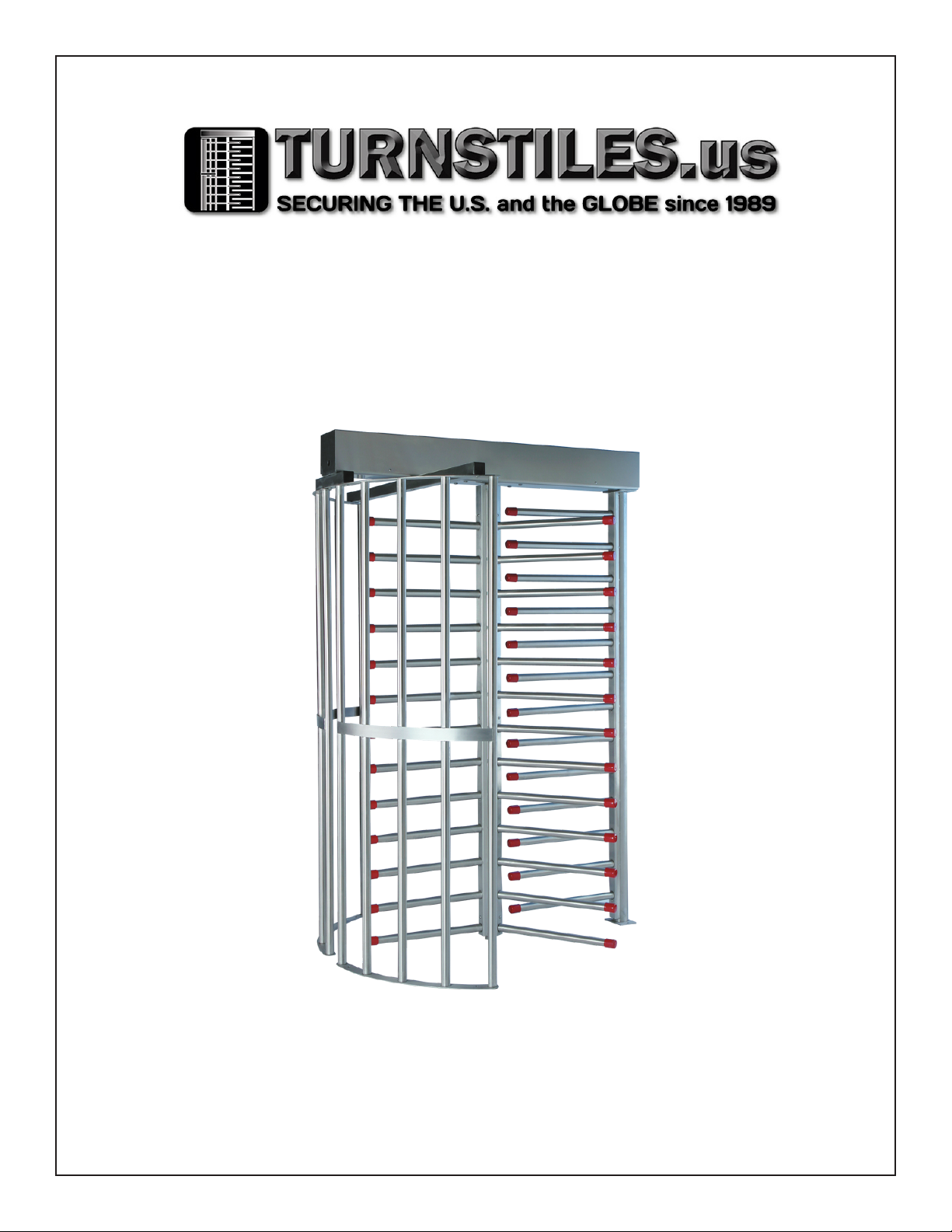
The High-Security Series HS427-S |HS430-S |HS439-S |HS448-S
Full-Height Turnstile (Single) |Interior & Exterior Application
Available Finishes:
• Hot dipped galvanized carbon steel
• Carbon steel with powder coating
(standard color is black/ other colors available upon request)
• Our signature 304 stainless steel, No. 4 satin
nish, or 316 stainless
Operation Features
6500 Series Control Head:
• Auto-indexing (self-centering) with adjustable
hydraulic shock suppression
• Hardened tool steel locking bars, cam and
roller assemblies
• Permanently lubricated bearings
• Your choice of manual or electronic control on
both directions
• Nearly universal integration to any number of
access control systems
• Your choice on each electronic direction of
locking or unlocking on power failure
Options:
• Card reader mounting plates
• Daylight visible indicator lights
• Bi-directional key overrides
• Lockout bar (padlock not included)
• Decorative arm caps
• Stainless steel overhead full canopy
• Half canopy (covers passageway)
• 8 digit key resettable LCD counter with seven
year lithium battery
• Cold weather package, including thermostat
controlled heater and insulated mainframe
• Push button and wireless remotes
• Heel guard arm covers
• Additional options available upon request
Warranty:
Units are warranted against defects in materials
and workmanship for a period of one year from
date of delivery. See warranty information for
specic details.
Matching Swing Gate available:
(see model HS336 and model HS348 Manual
Passage Gate information)
* Dimensions are approximate based on chart on reverse side
Electrical Specications:
Input Voltage: 100-240 VAC
Input Current: 1.3 - .55 A
Frequency: 50/60 Hz
Storage Temperature: -40 to 158°F
Operating Temperature: -4 to 131°F
(Cold weather package available)
Operating Voltage: 24VDC
Operating Current: 1.2 A (typical)
Standards and Codes:
Austenitic stainless steel:
ASTM A240, A249, A276
Hot rolled steel:
AISI C-1020, AISI C-1018
Hot dipped galvanizing:
ASTM A-143, ASTM A-153-80
All fasteners provided meet IFI ANSI/
ASME Fastener Standards
American Welding Society (AWS)
Standard D 1.1
4008027
The 6500 Series Control Head
is certified to conform to the
following standards:
UL 294, UL 325, UL Subject 2593,
CAN/ULC S319 & CSA C22.2#247
Advantage International Registrar to
be an ISO 9001:2015 company
* Dimensions are subject to change without notice
Applications:
Ideal for controlling orderly ow of foot trafc in
both indoor and outdoor settings
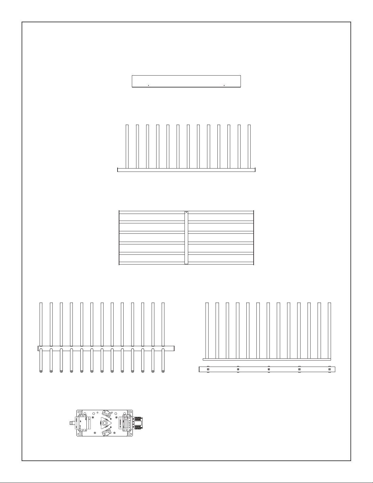
Design & Construction:
• Designed for secure operation with
aesthetics in mind
• Featuring fully welded exterior components
• Minimal exposed stainless steel hardware
• Heavy gauge materials meeting
ASTM standards
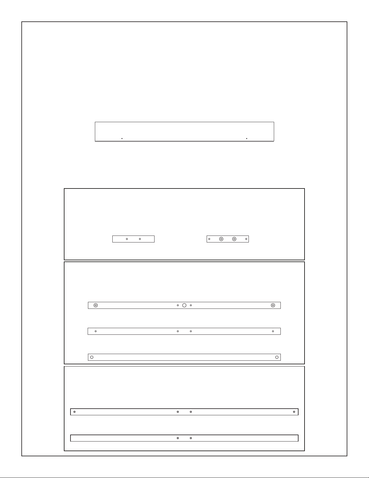
Dimensions:
HS427-S
•Pedestrian Clearance: 27” (685.8mm)
•Width: 62” (1574.8mm)
•Depth: 57.375” (1457.3mm)
HS430-S
•Pedestrian Clearance: 30” (762mm)
•Width: 66” (1676.4mm)
•Depth: 59.250” (1505mm)
Arm & Barrier Tubing Sizes
(HS427-S & HS430-S):
• Standard: 1 1/2” (38.1mm) diameter 14 gauge
• Optional: 1 3/4” (44.4mm) diameter 14 gauge
(16 gauge – Stainless Steel models)
HS439-S
•Pedestrian Clearance: 38.5” (978mm)
•Width: 84” (2133.6mm)
•Depth: 76” (1930.4mm)
HS448-S
•Pedestrian Clearance: 49.319” (1252.7mm)
•Width: 106” (2692.4mm)
•Depth: 96.187” (2443.1mm)
Arm & Barrier Tubing Sizes
(HS439-S & HS448-S):
• Standard: 1 3/4” (44.4mm) diameter 14 gauge
All Models:
•Overall Exterior Height: 91” (2311.4mm)
•Passage Height: 84” (2133.6mm)
•Removal of Cover: Minimum of 4” needed
www.TURNSTILES.us
Patrick.McAllister@TURNSTILES.us
303-670-1099
HS400 Series Single Full Height Turnstile Service & Installation Manual