Maco Atrium HS Comfort drive User manual

TECHNIK DIE BEWEGT
www.maco.eu
RAIL-SYSTEMS SCHIEBEBESCHLÄGE/ SLIDING HARDWARE
HS-Beschläge/HS-hardware
HS comfort drive
Holz, Holz-Alu verdecktliegend
Timber/ Timber-Alu covered
MONTAGEHINWEISE/INSTALLATION INSTRUCTIONS
Verwendung
ausschließlich für Fachbetrieb!
Use
exclusively for specialist companies!

2
TECHNIK DIE BEWEGT
Inhaltsverzeichnis Table of content
Wichtige Sicherheitsanweisungen�������������������������������������������3-6
Abkürzungen �����������������������������������������������������������������������������6
Gewährleistung ��������������������������������������������������������������������������6
Entsorgung �������������������������������������������������������������������������������6
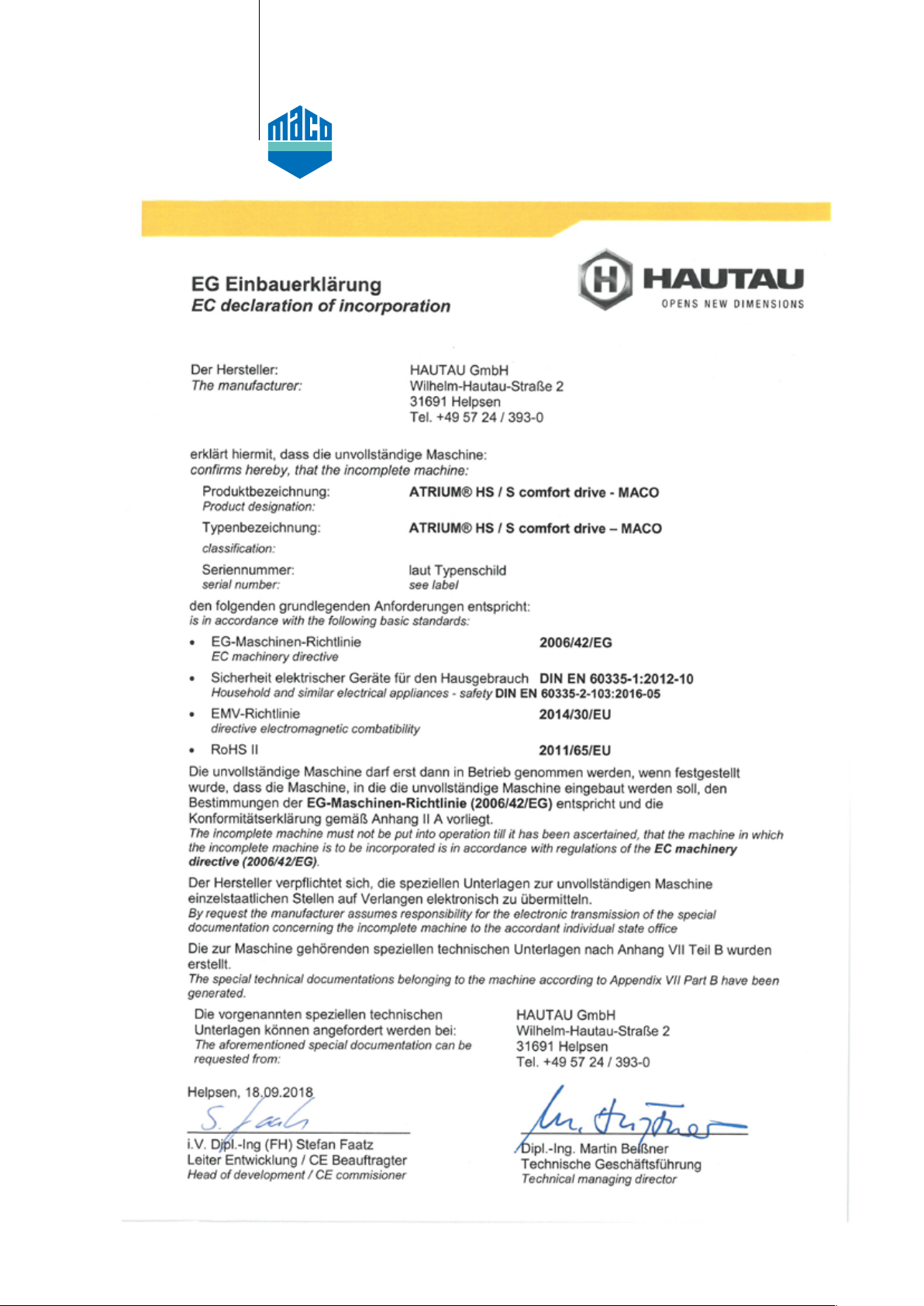
EG-Einbauerklärung�������������������������������������������������������������������7
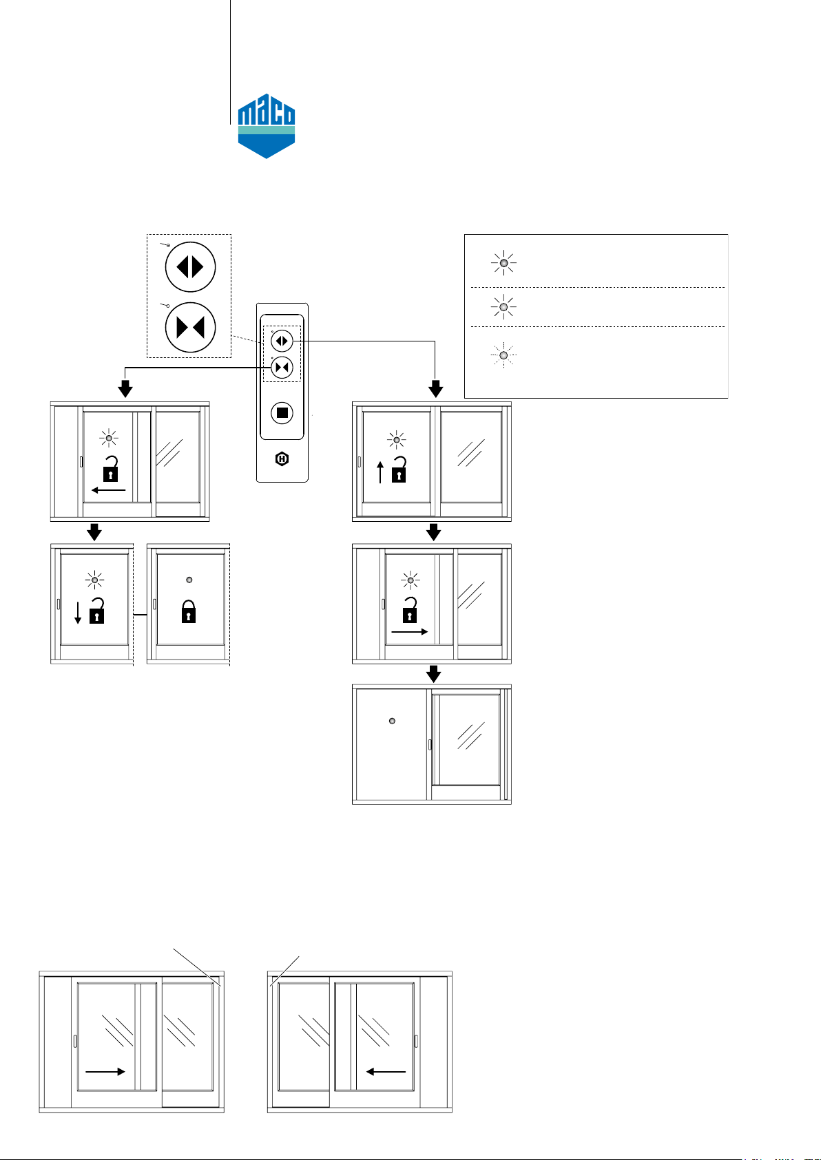
Bedienung/Begriffsklärung ���������������������������������������������������������8
Manuelle Entriegelung/Verriegelung bei Stromausfall����������������9
Teileübersicht ���������������������������������������������������������������������10-11
Vorbereitende Maßnahmen �����������������������������������������������������12
Vorbereitung des elektrischen Anschlusses�����������������������������12
Fräsarbeiten am Rahmen
Platinenfräsung ������������������������������������������������������������������������13
Motorfräsung ���������������������������������������������������������������������������14
Verschluss, Bedien- und Stromübergang���������������������������������15
Fräsarbeiten am Flügel
Schlosskastenfräsung, Hubantriebfräsung, Hakenkastenfräsung��16
Mitnehmerpositionierung ����������������������������������������������������17-18
Bohrungen für manuellen Entriegelungsgriff ���������������������������19
Montage am Rahmen
Montage Antriebseinheit�����������������������������������������������������������20
Montage Aufnahme Abdeckblende �����������������������������������������21
Montage Zahnriemen ��������������������������������������������������������������22
Mitnehmer mit Zahnriemen verbinden��������������������������������������23
Montage Führungsschiene�������������������������������������������������������24
Montage Platine������������������������������������������������������������������������25
Montage Magnete���������������������������������������������������������������������26
Möglichkeiten der Kabelführung ����������������������������������������������27
Montage Stromübergang und Bedienteil����������������������������������28
Montage Hakenschließteil ��������������������������������������������������������29
Montage am Flügel
Montage Laufwagen ����������������������������������������������������������������30
Montage Getriebe���������������������������������������������������������������������31
Haken und Hakenschließteile fetten�����������������������������������������32
Montage Mitnehmeraufnahme �������������������������������������������������32
Flügel einhängen ���������������������������������������������������������������������33
Einstellung Zahnriemenspannung��������������������������������������������34
Abdeckblenden ablängen ��������������������������������������������������������35
Montage Abdeckblenden für Zahnriemen �������������������������������35
Einkoppeln des Hubantriebs�����������������������������������������������������36
Elektrischer Anschluss
Elektronischer Anschluss ���������������������������������������������������������37
Anschlussbox ���������������������������������������������������������������������������38
Anschlussplan (Beispiele) ���������������������������������������������������39-42
DIP-Schalter kontrollieren/einstellen ���������������������������������������43
Auslösung von „Full-Init“ und „Home-Init“ ��������������������������������44
Erstinbetriebnahme („Full-Init“) �������������������������������������������44-45
Normal-Betrieb ������������������������������������������������������������������������46
Einlernfahrt („Home-init“) ���������������������������������������������������������47
Sicherheitsfunktionsprüfung „Reversierung“ ���������������������������48
Montage der Abdeckung Elektronik ������������������������������������������49
Montage der Abdeckung für die manuelle Ent-/Verriegelung ����� 49
Fehlerbehebung ����������������������������������������������������������������������50
Wartung/Instandhaltung ����������������������������������������������������������50
Pege ��������������������������������������������������������������������������������������50
Technische Daten ��������������������������������������������������������������51-52
Montage IR-Lichtvorhang ���������������������������������������������������53-58
Montage IR-Anwesenheitsmelder �������������������������������������������59
Anschluss 1-Tasten-Bedientaster ��������������������������������������������60
Important safety instructions ���������������������������������������������������3-6
Abbreviations������������������������������������������������������������������������������6
Warranty ������������������������������������������������������������������������������������6
Disposal ������������������������������������������������������������������������������������6
EG-Declaration���������������������������������������������������������������������������7
Operation/Explanation of terms��������������������������������������������������8
Manual release/locking in case of power failure�������������������������9
Parts overview���������������������������������������������������������������������10-11
Preparatory actions ������������������������������������������������������������������12
Preparation of electrical connection �����������������������������������������12
Milling on the frame
Cut-outs for circuit board ����������������������������������������������������������13
Cut-outs for motor ��������������������������������������������������������������������14
Locking, control keypad and current transition�������������������������15
Milling on the sash
Cut-outs for lock case, lift-drive and hook-box �������������������������16
Positioning of the drive pin ������������������������������������������������17-18
Borings for manual unlocking handle ���������������������������������������19
Mounting on the frame
Mounting driving unit ���������������������������������������������������������������20
Mounting of cover prole ����������������������������������������������������������21
Mounting tooth belt ������������������������������������������������������������������22
Connect drive pin with toothbelt �����������������������������������������������23
Mounting guide track ����������������������������������������������������������������24
Mounting circuit plate����������������������������������������������������������������25
Mounting magnets �������������������������������������������������������������������26
Possbilities of cable routing������������������������������������������������������27
Mounting current transition and control keypad������������������������28
Mounting hook locking part�������������������������������������������������������29
Mounting on the sash
Mounting bogies ����������������������������������������������������������������������30
Mounting gear���������������������������������������������������������������������������31
Lubrication of hook drive gears and striker plates��������������������32
Mounting drive support ������������������������������������������������������������32
Hooking the sash����������������������������������������������������������������������33
Adjustment of tension of tooth belt �������������������������������������������34
Cover prole cut to length���������������������������������������������������������35
Mounting cover proles for tooth belt ��������������������������������������35
Coupling of lift drive �����������������������������������������������������������������36
Electrical connection
Electrical connection ����������������������������������������������������������������37
Connection box ������������������������������������������������������������������������38
Connecting diagram (examples)������������������������������������������39-42
Check/Adjust DIP switch ����������������������������������������������������������43
Triggering of “Full-Init“ and “Home-Init“ �����������������������������������44
First start up (“Full-Init“) ������������������������������������������������������44-45
Standard operation ������������������������������������������������������������������46
Teach-in run (“Home-init“) �������������������������������������������������������47
Safety function check «reversing» �������������������������������������������48
Mounting of the cover electronics ���������������������������������������������49
Mounting of the cover for manual release/locking ���������������������49
Fault elimination ����������������������������������������������������������������������50
Maintenance/repair ������������������������������������������������������������������50
Care �����������������������������������������������������������������������������������������50
Technical specication �������������������������������������������������������51-52
Installation IR light curtain ��������������������������������������������������53-58
Installation IR presence sensor �����������������������������������������������59
Connection of 1-button control pushbutton ������������������������������60

3
TECHNIK DIE BEWEGT
Für die Sicherheit von Personen ist es wichtig, die folgen-
den Anweisungen zu befolgen� Falsche Montage kann zu
schweren Verletzungen führen!
Herstellererklärung/Stand der Technik
Der Antrieb wurde gemäß der anzuwendenden europäischen
Richtlinien geprüft und hergestellt� Eine entsprechende
Einbauerklärung liegt vor� Sie dürfen die Geräte nur betrei-
ben, wenn für das Gesamtsystem eine Konformitätserklärung
vorliegt�
Der Antrieb entspricht dem Stand der Technik und erfordert
qualiziertes Fachpersonal bei der Montage, Wartung etc.
Personal
Die fachgerechte Ausführung des elektrischen Anschlusses
darf nur durch eine Elektrofachkraft (z� B� nach DIN VDE
1000-10) erfolgen! Der Einbau des Antriebs muss durch
Personal erfolgen, welches entsprechend dem Stand und
nach anerkannten Regeln der Technik unterwiesen wurde�
Bestimmungsgemäßer Gebrauch
- Ein kraftbetätigtes (Hebe-) Schiebefenster mit horizontal
verschiebbaren Flügelelementen, dient als Neben-Ein-/
Ausgang zwischen zwei voneinander getrennt liegenden
Bereichen, zur Verbindung von Außen- und Innenbereichen�
- Einsatz des HS/S comfort drive nur für Flügel mit einem
Gewicht von max� 300 kg (integrierter Einklemmschutz)�
Bei Flügelgewichten von 300 ... 440 kg müssen, je
nach Gefährdungsbeurteilung, zusätzliche Sicherheits-
einrichtungen wie z.B. Lichtvorhang, Anwesenheits-
melder oder Schlüsseltaster angebracht werden.
- Das Komplettelement darf nur senkrecht montiert werden�
- Zu Wartungszwecken müssen alle Komponenten am
Fensterelement frei zugänglich sein�
- In geschlossener Stellung ist der Flügel abgesenkt und
durch Schließhaken verriegelt�
- Das Hebe-Schiebefenster ndet keine Verwendung als
Feuerschutz-, Rauchschutz- oder Rettungstür�
- Bei Ausführung mit Hubantrieb: bei Energieausfall kann
der Verschiebeügel mit einem einsteckbaren Handhebel
angehoben/abgesenkt und von Hand langsam verschoben
werden� Eine Ent-/Verriegelung in geschlossener/offener
Stellung wird dadurch möglich�
Stimmen Sie benötigtes Befestigungsmaterial mit dem
Baukörper und der entsprechenden Belastung ab und ergänzen
Sie es, wenn nötig� Ein eventuell mitgeliefertes Befestigungs-
material entspricht nur einem Teil der Erfordernisse�
Alle nicht dem bestimmungsgemäßen Gebrauch entspre-
chenden Einsatzfälle oder Änderungen am Antrieb sind
ausdrücklich verboten� Bei Nichteinhaltung übernehmen wir
keinerlei Haftung für Schäden an Personen oder Material�
Beachten Sie auch die „Vorgaben und Hinweise zum Produkt
und zur Haftung (VHBH)“ von der Gütegemeinschaft Schlösser
und Beschläge e�V�
The safety of personnel requires that the following instructions
be observed� Incorrect installation can lead to severe injury!
Declaration of Conformity/state of the art
The drive has been constructed and tested in conformity with
all applicable European directives� A corresponding declaration
of incorporation is available� You may not operate the equip-
ment unless a declaration of conformity is available for the
overall system�
The drive complies with the state of the art and requires
qualied personnel for installation, maintenance, etc.
Personnel
Professional execution of electrical connection has to be
entrusted to trained electricians! (as specied e. g. in DIN VDE
1000-10)�
The mounting of the drive has to be performed by personnel,
which has been instructed acc� to the state of the art and acc�
to recognised rules of technology�
Intended use
- A power-operated (lift and) slide window with horizontally
slidable sashes is used as a side entrance and side exit
between two separate locations, in order to link interior and
exterior�
- Use of the HS/S comfort drive only for sashes with a weight
of max� 300 kg (integrated anti-trap protection)�
Depending on the risk assessment, for sash weights
of 300 ... 440 kg additional safety devices, such as light
curtain, presence sensor or key switch have to be installed.
- The complete element has to be mounted perpendicularly�
- For maintenance purposes all components of the window
element have to be freely accessible�
- In closed position, the sash is lowered and locked by means
of locking hooks�
- The lift and slide window cannot be used as emergency door
for re protection, smoke protection or as escape door.
- For version with lift drive: in case of power failure it is possib-
le to manually lift, lower and slide the movable sash with a
plug-in handle� This enables a release/locking in open/closed
position�
Select the required mounting material in accordance with the
structure and the respective load and use additional mounting
material if necessary� Any included mounting material will only
correspond to parts of the required material�
Any individual applications or modications of the drive
which are not in compliance with intended use are explicitly
prohibited� We shall not be liable for any damage to personnel
or material resulting from non-compliance with this provision�
Pay attention to the „Guidelines/advice on the product and on
liability“ (VHBH) of the Quality Assurance Association: Locks
and Hardware�
WARNUNG:
Wichtige Sicherheits-
anweisungen!
WARNING:
Important safety instructions!

4
TECHNIK DIE BEWEGT
WARNUNG:
Wichtige Sicherheits-
anweisungen! (Fortsetzung)
WARNING:
Important safety instructions!
(continuation)
Aufbewahrung von Dokumenten/Einweisung
Bewahren Sie diese Montageanleitung für den späteren
Gebrauch und die Wartung auf� Händigen Sie die Bedienungs-
anleitung dem Endanwender aus und nehmen Sie eine
Einweisung vor�
Installation und Bedienung
Vor der Montage: Fenster und Sicherheitselemente testen�
Die Unversehrtheit und Leichtgängigkeit des Fensters sind
sicherzustellen�
Alle Arbeiten (Montage, Einstellung usw�) sind in stromlosem
Zustand durchzuführen�
Vor dem Einbau des Antriebs muss geprüft werden, ob der
geltende Temperaturbereich auf die Umgebung abgestimmt ist�
Zur Befestigung der Teile verwenden Sie ausreichend
lange Schrauben, welche bei Kunststoff-Prolen bis in die
Stahlarmierung reichen müssen�
Beim Betätigen eines Schlüsselschalters mit Aus-Voreinstellung
(Totmann-Schalter) dürfen sich keine weiteren Personen im
Umfeld des Antriebs aufhalten�
WARNUNG: Schließen Sie den Antrieb/das Bedienteil
nie an 230 V an!
Der Antrieb darf nur mit Sicherheitskleinspannung
betrieben werden� Andernfalls besteht Lebensgefahr!
ACHTUNG: Falls Sie die Arbeitsschritte nicht
beachten, führt dies zur Zerstörung des Antriebs�
Falsche Handhabung gefährdet das Material� Lassen
Sie keine Flüssigkeit ins Geräteinnere gelangen!
Es sind keine Gegenstände und Schmutz auf der
Laufschiene zu belassen�
Quetsch- und Klemmgefahr!
Zur Vermeidung einer Fehlanwendung ist am Einbau-
ort eine Risikobeurteilung nach Maschinenrichtlinie
2006/42/EG erforderlich� Schutzmaßnahmen sind
nach EN 60335-2-103/2016-05 anzuwenden�
Bei Flügelgewichten von 300 ��� 440 kg müssen, je
nach Gefährdungsbeurteilung, zusätzliche Sicherheits-
einrichtungen wie z�B� Lichtvorhang, Anwesenheits-
melder oder Schlüsseltaster angebracht werden�
Storing documents/instructions
Store these instructions for future reference and maintenan-
ce� Make these installation instructions available to the end
user and provide instructions�
Installation und operation
Prior to installation: Test window and safety elements�
The physical integrity and smooth operation of the window
must be ensured�
All works (installation, adjustment etc�) have to be done in
currentless condition�
Before installing the drive, it must be veried that the drive‘s
temperature range has been adapted to its operating environ-
ment�
To fasten the parts, use screws with sufcient length, so that
they can reach into the steel reinforcement in case of PVC
proles.
No other persons are allowed in the vicinity of the drive when
a key switch with off presetting (deadman switch) is actuated�
WARNING: Never connect the drive/control keypad to
230 V of voltage! The drive may only be operated at
very low safety voltage� Otherwise, there is danger
to life!
CAUTION: Failure to follow the work steps will destroy
the drive� Improper handling endangers the material�
Do not allow any liquid to enter the interior of the device!
No objects or dirt shall be left on the running rail�
Risk of crushing and pinching!
To avoid misuse, a risk assessment acc� to Machinery
Directive 2006/42/EC is required at the installation site�
Protective measures are to be applied according to
EN 60335-2-103/2016-05�
Depending on the risk assessment, for sash weights
of 300 ��� 440 kg additional safety devices, such as
light curtain, presence sensor or key switch have to
be installed�

5
TECHNIK DIE BEWEGT
WARNUNG:
Wichtige Sicherheits-
anweisungen! (Fortsetzung)
WARNING:
Important safety instructions!
(continuation)
Der Antrieb öffnet und schließt Fenster automatisch�
Er stoppt über eine Lastabschaltung� Die Druckkraft
reicht dennoch aus, um bei Unachtsamkeit Finger zu
zerquetschen�
Greifen Sie bei laufendem Antrieb nicht in den Durch-
gangsbereich und nicht in den Antrieb!
Dieses Gerät kann von Kindern ab 8 Jahren und
darüber sowie von Personen mit verringerten
physischen, sensorischen oder mentalen Fähigkeiten
oder Mangel an Erfahrung und Wissen benutzt werden,
wenn sie beaufsichtigt oder bezüglich des sicheren
Gebrauchs des Gerätes unterwiesen wurden und die
daraus resultierenden Gefahren verstehen�
Kinder dürfen nicht mit dem Gerät spielen�
Reinigung und Benutzerwartung dürfen nicht von
Kindern ohne Beaufsichtigung durchgeführt werden�
Stellen Sie sicher, dass sich im Bewegungsbereich der
Schiebetür keine Personen oder Gegenstände benden.
Verfügt das Schiebetür-Element über keine zusätzliche
Sicherheitseinrichtung (Lichtvorhang, Anwesenheits-
melder), dann betreiben Sie den Antrieb nur, wenn Sie
Sichtkontakt zur Tür haben�
Überwachen Sie den Türlauf, bis die Tür die Endlage
erreicht hat�
Durchgehen Sie ferngesteuerte Türen erst, wenn die
Tür zum Stillstand gekommen ist�
Stellen Sie sicher, dass Fernbedienungen nicht in
Kinderhände gelangen und nur von Personen benutzte
werden, die in die Funktionsweise der ferngesteuerten
Tür eingewiesen sind�
Bei der Bedienung mittels Fernbedienung muss Sicht-
kontakt zur Tür bestehen, wenn diese nicht über eine
zusätzliche Sicherheitseinrichtung (Lichtvorhang,
Anwesenheitsmelder) verfügt�
Beachten Sie, dass am Handsender versehentlich
eine Taste betätigt werden kann (z�B� in der Hosen- /
Handtasche) und es hierbei zu einer ungewollten
Türfahrt kommen kann�
Achten Sie darauf, dass sich beim Einlernen der Tür
keine Personen oder Gegenstände im Bewegungs-
bereich der Tür benden.
Prüfung
Überprüfen Sie nach der Installation und nach jeder
Veränderung der Anlage alle Funktionen durch Probelauf�
Hinweis:
Benötigen/wünschen Sie Ersatzteile oder
Erweiterungen, verwenden Sie lediglich
Original-Ersatzteile� Bei Verwendung von
Fremdfabrikaten keine Haftung, Gewähr- und
Serviceleistungen� Ein zuverlässiger Betrieb und
das Vermeiden von Schäden und Gefahren sind
nur bei sorgfältiger Montage/Einstellung nach
dieser Anleitung gegeben�
The drive opens and closes windows automatically�
It is stopped by overload cutoff� However, the compres-
sive force is suf cient to crush ngers if you act
carelessly�
Do not reach into the window rebate or the drive while
the drive is running!
This device may be used by children age 8 and older
as well as all persons without limited physical, senso-
ry or mental abilities or lack of experience and
knowledge provided they act under supervision or
have received prior instructions on the safe use of the
device and any hazards resulting from using the
device�
Children are not allowed to play with the device�
Cleaning and user maintenance must not be carried
out by children without supervision�
Make sure there are no people or objects in the
movement area of the sliding sash�
If the sliding sash element does not have additional
safety devices, such as light curtain or presence
sensor, you have to operate the drive only when there
is visual contact with the door�
Observe the run of the sash until the door has
reached the end position�
Do not pass through remote-controlled doors until the
door has stopped�
Make sure that remote controls do not come into the
hands of children and are only used by people who
are familiar with the operation of the remote-control-
led door�
When operating with a remote control, there must
be visual contact with the door if it does not have
an additional safety device (light curtain, presence
sensor)�
Please note that a button can be accidentally pressed
on the hand-held transmitter (for example in the
pocket/ handbag) and this can lead to an unintended
door movement�
Make sure that there are no persons or objects in the
movement area of the door when teaching-in the door�
Testing
When installation is complete and after any changes
to the system, check all functions by a trial run�
Note:
If spare parts or extension components are requi-
red or desired, use only original spare parts� No
liability will be accepted and no guarantee nor
service is granted if products made by outside
manufacturers are used�
Reliable operation without any damage and
hazards requires that installation/setup be made
carefully in accordance with these instructions�

6
TECHNIK DIE BEWEGT
Wartung/Instandhaltung
Die Stromzufuhr zum Antrieb muss unterbrochen werden, wenn
Reinigungs- oder andere Wartungsarbeiten durchgeführt werden�
Die Fenster und Antriebe müssen mindestens 1x jährlich auf
Unversehrtheit überprüft und gewartet werden�
Die Antriebe von Verunreinigungen befreien� Befestigungs- und
Klemmschrauben auf festen Sitz prüfen� Die Zahnriemen-
spannung ist jährlich zu kontrollieren und der Zahnriemen ist
ggf� nachzuspannen (s� Abschnitt „Einstellung der Zahnriemen-
spannung“)� Die zu überprüfenden Teile und zu wartenden Punkte
sind der Wartungscheckliste (www�hautau�de) zu entnehmen� Der
Endkunde kann alle beschriebenen Schritte selbst durchführen�
Beim Abweichen von den Anweisungsschritten ist jedoch mit der
Einschränkung von Garantieansprüchen zu rechnen�
Den Antrieb durch Probelauf testen� Defekte Antriebe dürfen nur
in unserem Werk instandgesetzt werden� Es dürfen nur Original-
Ersatzteile eingesetzt werden�
Die Betriebsbereitschaft ist regelmäßig zu prüfen�
Pege
Alle Geräte und Kabelanschlüsse auf äußere Beschädigung
und Verschmutzung prüfen� Das Bedienteil darf nicht in seiner
Funktionstüchtigkeit, z� B� durch bauliche Maßnahmen oder
Lagergut, beeinträchtigt werden�
Für die Reinigung der Gehäuseteile und des Bedienteils verwen-
den Sie ein weiches, leicht befeuchtetes Tuch� Um eine Beschädi-
gung der Oberächen zu vermeiden, verwenden Sie für die Reini-
gung keine ätzenden Chemikalien, aggressiven Reingungslösun-
gen oder lösungsmittelhaltigen Mittel� Schützen Sie den Antrieb
dauerhaft vor Wasser/Schmutz�
Maintenance/repair
The power supply to the device must be interrupted for
the duration of any cleaning or other types of maintenance
operations�
Windows and drives must be checked for physical integrity at
least once a year�
Free the drives from any contamination� Check the tightness
of xing and clamping screws. The tension of tooth belt
has to be checked every year and the tooth belt has to be
retensioned, if necessary (refer to section “Adjustment of
tension of tooth belt“)� The parts to be checked and the items
to be maintained can be found in the maintenance check
list (www�hautau�de)� The end customer can perform all of the
steps described� If deviating from the instruction steps, limitation
of warranty claims must be expected�
Test the drive by trial run� Defective drives must be repaired
at our factory� You may only use original spare parts�
The readiness for operation has to be checked regularly�
Care
Check all devices and cable connections for external damage
and dirt� The operability of the control keypad must not be
affected by, for example, structural measures or stored goods�
Use a soft, slightly dampened cloth to clean the housing
components and the control keypad� To prevent damage
to the surfaces, do not use any caustic chemicals, abrasive
cleaners or agents containing solvents for cleaning� Provide
the drive with durable protection against water and dirt�
WARNUNG:
Wichtige Sicherheits-
anweisungen! (Fortsetzung)
WARNING:
Important safety instructions!
(continuation)
Abkürzungen
HS/S Hebe-Schiebe/Schiebe ���
LH Länge Hubantrieb
RAB Rahmenaußenbreite
Abbreviations
HS/S Lift & Slide/Slide ���
LH Length of lift drive
RAB Outer frame width
Entsorgung
Das Symbol des durchgestrichenen Mülleimers
besagt, dass dieses Elektro- bzw� Elektronikgerät
am Ende seiner Lebensdauer nicht im Hausmüll
entsorgt werden darf�
Zur Rückgabe stehen in Ihrer Nähe kostenfreie Sammel-
stellen für Elektroaltgeräte sowie ggf� weitere Annahme-
stellen für die Wiederverwendung der Geräte zur Verfügung�
Die Adressen erhalten Sie von Ihrer Stadt- bzw� Kommunal-
verwaltung� Sofern das alte Elektro- bzw� Elektronikgerät
personenbezogene Daten enthält, sind Sie selbst für deren
Löschung verantwortlich, bevor sie es zurück geben� Weitere
Informationen nden Sie auf www.elektrogesetz.de bzw. für
andere Sprachen auf Internetseiten zur WEEE-Richtlinie�
Disposal
The crossed-out wheeled bin symbol indicates that you
must not dispose of this electrical appliance or electronic
device in the household waste at the end of its service
life�
You can return it to free collection points for old electrical applian-
ces in your area or to other centres where they accept old appli-
ances for recycling� Contact your local council for addresses of
collection points and centres� If the electrical appliance or electro-
nic device contains personal data, you yourself are responsible
for erasing data before you return it. You will nd more information
online at www�weeelogic�com or other websites on the WEEE
Directive�
Gewährleistung
Für den Antrieb gelten die Allgemeinen Geschäftsbedingun-
gen (AGB) der Fa� HAUTAU (Internet: www�HAUTAU�de)�
Warranty
The drive is subject to HAUTAU’s Terms and Conditions (TC)
(Internet: www�HAUTAU�de)�

7
TECHNIK DIE BEWEGT

8
*
*
1
1
1
1
1
2
2
1
1
1
2
TECHNIK DIE BEWEGT
Grün leuchtet während der Bewegung
des Hub-/Verschiebeantriebs
Green lights during movement of the lift/
sliding drive
Während des Initlaufs blitzt Gelb;
nach Abschluss des Initlaufs sind die
LEDs erloschen
During Init run Yellow is ashing; after
nishing the Init run, both LEDs are off
Gelb leuchtet bei einem Fehler
Yellow lights in case of fault
Schließen / Closing Öffnen / Opening
Bedienung
Operation
Begriffsklärung
Explanation of terms
*) nur bei HS comfort drive
for HS comfort drive, only
linke Ausführung
(Schiebeügel von links nach rechts
öffnend, Antriebsmodul rechts)
left version
(sliding sash opening from the left to the right,
drive module on the right)
rechte Ausführung
(Schiebeügel von rechts nach links
öffnend, Antriebsmodul links)
right version
(sliding sash opening from the right to
the left, drive module on the left)
Als Beispiel ist in dieser Anleitung ein nach rechts
öffnender Flügel dargestellt� Maße und Arbeits-
schritte für nach links öffnende Flügel sind
entsprechend zu adaptieren�
Maßangaben in mm�
As an example, a sash opening to the right is
described within these mounting instructions�
Measurements and procedures for sashes
opening to the left have to be adapted accordingly�
Measurements in mm�

9
EIN
ON
AUS
OFF
2.2
2.1
3.1
3.2
4.2
4.1
5.1
5.1
ca.135°
5.2
6.3
6.3 6.2
A
B
6.2
6.1
1.
TECHNIK DIE BEWEGT
Manuelle Entriegelung/Verriegelung bei Stromausfall
Manual release/locking in case of power failure
1� Switch off electricity primary sided before the power
supply unit�
2� Remove the cap�
3� Insert the manual unlocking-handle into the gear and
move it a little to left and right, to release the gear�
4� Install the unlocking key and rotate it to the glazing side
until you hear a closure sound�
5� Now you can lift and open the sash with the unlocking
handle�
ATTENTION: Do not release the handle, guide the
handle in the locked position, because it turns
arround quickly due to the sash weight, thus
could cause heavy injuries.
Locking
6� Bring the coupling pin of the lift drive (A) in matching
position to the drill hole of the drive rod (B)� In order to
couple lift drive and drive rod, turn the unlocking key
towards the frame side (6�2)�
1� Stromzufuhr primärseitig vor dem Netzteil ausschalten�
2� Abdeckkappe entfernen�
3� Stecken Sie den manuellen Entriegelungsgriff in den
Getriebe-Vierkant und bewegen Sie ihn etwas nach links
und rechts, um das Getriebe zu lösen�
4� Führen Sie den Entriegelungsschlüssel ein und drehen Sie
diesen Richtung Verglasung, bis ein Schließgeräusch zu
hören ist�
5� Jetzt können Sie den Flügel mittels Entriegelungsgriff
anheben�
ACHTUNG: Lassen Sie den Griff nicht los, sondern
führen Sie diesen wieder in die verriegelte Position,
da er durch das Flügelgewicht hochschnellt und so
zu schweren Verletzungen führen kann.
Verriegelung
6� Bringen Sie den Kupplungsbolzen des Hubantriebs (A) und
das Bohrloch der Treibschiene (B) in Übereinstimmung und
schließen Sie mittels Entriegelungsschlüssel in Richtung
Flügelrahmen (6�2), um die Treibschiene und den Antrieb
wieder zu kuppeln�
WARNUNG:
Wird der manuelle Entriegelungsgriff vor der
elektrischen Inbetriebnahme nicht abgezogen,
kann dies zu schweren Körperverletzungen führen!
WARNING:
If the manual unlocking-handle will not be
pulled off before electrical start-up, this can lead to
severe injuries!
Sicherungsschrank
Fuse box

10
1
7
5
5
7
5
6
7
9
8
3
11 2
4
14
13
15 25
16
20
21
21
19
17
10
22
23
24
Holz*
12
5
3
4
13
18
16 20
19
15
**
TECHNIK DIE BEWEGT
Teileübersicht
Parts overview
*) nicht im Lieferumfang enthalten
not included within scope of delivery
**) nur bei bauseitigem 1-Tasten-Bedientaster
in case of 1-button control pushbutton on site, only
optional
Beispiel: linke Ausführung
(Schiebeügel von links nach rechts öffnend
(Ansicht von innen)
Example: left version
sliding sash opening from the left to the right (view from inside)

11
TECHNIK DIE BEWEGT
Teileübersicht
Parts overview
1Antriebseinheit/ Drive unit
2Platine/ Circuit board
3Netzteil/ Power pack
4Abdeckung Netzteil/ Cover power pack
5Obere Führungseinheit mit Zubehör/ Upper guide unit with accesoires
6 Umlenkung Zahnriemen/ Deection tooth belt
7Aufnahme Abdeckung/ Cover support
8 Abdeckblende/ Cover prole
9Zahnriemen/ Tooth belt
10 Klemmplatte Zahnriemen/ Clamping plates drive unit bootom
11 Abdeckung Elektronik Holz/ Cover electronics timber
12 Halteplatte und Magnet(e)/ Support plate and magnet(s)
13 Kabel für Hubantrieb/ cable for lift drive
14 Kabel für Bedienteil/ Cable for control keypad
Bedienteil/ Control keypad
Abdeckung manuelle Ent-/ Verriegelung (in Verbindung mit Hubantrieb)
Cover for manual release/locking (in connection with lift drive)
Hubantrieb/ Lift drive
Stromübergang/ current transition
Kontaktübergabe (in Verbindung mit Hubantrieb)/ Contact delivery (in connection with lt drive)
Set Notentriegelung (Steckgriff und Neubautenschlüssel) (in Verbindung mit Hubantrieb
Emergency release set (drive handle and universal key) (in connection with lift drive)
Hakenschließteil/ hook locking part
Schlüsseltaster / Key switch
Anschlussbox HS/S comfort drive
Connection box HS/S comfort drive
WLAN-Box / WLAN-Box
Taster-Box / Pushbutton-Box
16
17
18
19
20
21
22
23
24
25
15

12
Torx T10/T20/T25
410
~ 1050
320
30
18
2,9 x ...
TECHNIK DIE BEWEGT
Vorbereitung des elektrischen Anschlusses
Preparation of electrical connection
- Alle Verschraubungen am Fensterprol müssen ausreichend weit in das
Holz reichen.
- Teile auf Vollständigkeit prüfen.
- Notwendige Fräsungen sind in der Werkstatt vorzunehmen.
- benötigtes Werkzeug (dieses muss gemäß Anleitung bereitgestellt sein):
- All screwings have to reach sufciently into the timber.
- Check parts for completeness.
- Required milling must be done in the workshop.
- Tools to be used (these have to be provided acc. to instructions):
Vorbereitende Maßnahmen Preparatory actions
Netzteil
Power Pack
Antriebseinheit
Drive unit
Verbindungsleitung
mit Querschnitt 1,5 mm²
Connecting cable with 1,5 mm²
cross-section
spätere Position des
Bedienteils
later position of the control
keypad
Leerrohre Ø 16 mm für Kabel-
verlegung im Fräskanal
empty conduits Ø 16 mm for cable routing
within the reveal
Beispiel: linke Ausführung
(Schiebeügel von links nach rechts öffnend
(Ansicht von innen)
Example: left version
sliding sash opening from the left to the right (view from inside)

13
40
56
46
==
18
Ø12
Ø12
94
10
84
21
26
300
340
345
R8
R8
R8
R8
R8
317
38 2
10,5
63
22
50
75
R8
R8
R8
R8
Ø12
40
46
10
22
75
300
317
75
656
50
10
16
345
339
21
84
46
75
300
657
17
50
345
50
BA
CC
B-B
C-C
D-D
A-A
X
X
DD
BA
TECHNIK DIE BEWEGT
Fräsarbeiten am Rahmen
Platinenfräsung Milling on the frame
Cut-outs for circuit board

14
Y
Y
E
G
G
F
FG-G
F-F
EE-E
120
16
R8
120
16 16
12,5
22
25
6
169
175
12,515,5
82
50
92
192
R8
R8
Ø9
Ø9
L= RAB/2+240
24
Ø9
12,5
25
22
27,5
54
42
43
12
43
12
86
50
82
66,5
74
L= RAB/2+116
==
TECHNIK DIE BEWEGT
Fräsarbeiten am Rahmen
Fräsung Antriebseinheit
Milling on the frame
Cut-outs for drive unit

15
B ± 1,5
A ± 1,5
C ± 1,5
A; B; C;
A; B; C;
DD
16
120
16
16
120
16
39
40
12
12
10
3
120
16
16
16
Ø16
Ø12
R8
R8
Ø16
GM-95
R8
C
BB
17
AB
145 733
733145
Gr. 4
Gr. 5
C
1613
2045
D
1794Gr. 4
Gr. 5 2342
D
12
Ø12
10
64
16
13
3
12
40
16
16
12
TECHNIK DIE BEWEGT
Fräsarbeiten am Rahmen
Verschluss, Bedien- und Stromübergang Milling on the frame
Locking, control- and current transition
Hakengetriebe/ hoook gear
Hakengetriebe Gr� 4 Position B ist optional
hoook gear size 4 position B is optional
Hakengetriebe/ hoook gear
(Größe 4 / size 4)
(Größe 5 / size 5)
(Größe 4 / size 4)
(Größe 5 / size 5)

16
B
B
46
22
63
254230
230
115115254
1000
1010
X
X
A
B
X
125
Gr. 4
Gr. 5 292
80
22
28
22
22
8
50
C
C
C
C
C
A
Y
B
A
166
Gr. 4
Gr. 5166
754
754
1634
2066
BC
46 56300 kg
Y
TECHNIK DIE BEWEGT
Fräsarbeiten am Flügel
Schlosskastenfräsung
Hubantriebfräsung
Hakenkastenfräsung
A
B
CC
Milling on the sash
Cut-outs for lock case
Cut-outs for lift-drive
Cut-outs for hook-box
Hakengetriebe Gr� 4 Position B ist optional
hoook gear size 4 position B is optional
(Größe 4 / size 4)(Größe 4 / size 4)
(Größe 5 / size 5)(Größe 5 / size 5)
B
A

17
145
4,5 x...
B
==
22
115
34
40
Ø7
R8
B
115
1021
TECHNIK DIE BEWEGT
Fräsarbeiten am Flügel
Mitnehmerpositionierung Milling on the sash
Cut-outs for drive pin
Gilt bis auf Widerruf gegenüber Seite18!
Until further notice valid against page 18!
Bolzen darf max. 4 mm
rausstehen
Bolts may extend by max. 4 mm

18
145
4,5 x...
B
==
22
115
40
Ø7
B
115
1021
TECHNIK DIE BEWEGT
Fräsarbeiten am Flügel
Mitnehmerpositionierung Milling on the sash
Cut-outs for drive pin
Bolzen darf max. 4 mm
rausstehen
Bolts may extend by max. 4 mm

19
4040
12
69
83,5
45,5
Ø 20
4040
12
69
83,5
45,5
Ø 20
TECHNIK DIE BEWEGT
Fräsarbeiten am Flügel
Bohrungen für manuelle
Entriegelungsgriff
Löcher für manuelle Entriegelungsgriff
und Entriegelungsschlüssel bohren
Bore holes for manual unlocking-handle and
unlocking key
Löcher für Abdeckung manuelle
Ent-/ Verriegelung bohren
Bore holes for cover for manual release/locking
nur bis auf Tiefe der
Getriebe-Box bohren
bore until depth of espag
box, only
Milling on the sash
Borings for manual
unlocking handle
nur bis auf Tiefe
der Getriebe-Box
bohren
bore until depth of espag
box, only

20
6x
4,5 x ...
X
4x
4,5 x ...
TECHNIK DIE BEWEGT
Montage am Rahmen
Montage Antriebseinheit
Montage der Umlenkung des Zahnriemens
Mounting of deection tooth belt
Mounting on the frame
Mounting driving unit
Antriebseinheit mittels der beiden Ansatzdorne
unterhalb der oberen Zarge in der gefrästen Tasche
positionieren und mit 6 Schrauben befestigen
By means of both pins, position the drive unit below the upper frame within
the milled pocket and fasten it with 6 screws
Fensterbau-Schraube (bauseits)
Window screw (on site)
Ansicht X / View X
Schließrichtung
Closing direction
Fensterbau-Schraube (bauseits)
Window screw (on site)
Schließrichtung
Closing direction
Es wird empfohlen, am losen Stab zu montieren.
It is recommended to mount on the loose rod.
This manual suits for next models
1
Other Maco DC Drive manuals
Popular DC Drive manuals by other brands

Motor City Wash Works
Motor City Wash Works POWERSYS0013 manual

SOMFY
SOMFY HOME MOTION Orea WT Series Original instructions

Toshiba
Toshiba Q9+ Installation & operation manual

Leadshine
Leadshine EM522-CAN user manual

Emerson
Emerson Unidrive HS72 Control Getting Started Guide

Vacon
Vacon NXP series System hardware manual

Siemens
Siemens SINAMICS G120 manual

Chauvet Professional
Chauvet Professional onAir Flex Drive 2 Quick reference guide

ABB
ABB ACS880-04 drive modules Application guide

ITEM
ITEM LRE 8 D25 ZU 80 R50 Notes on Use and Installation

SEW-Eurodrive
SEW-Eurodrive MOVITRAC B System manual

Rockwell Automation
Rockwell Automation Reliance electric GV3000/SE user guide