Maco HAUTAU SKA 50-500 User manual

B
L
H
12
100,5
66
18
A Dachfenster (DF)
Skylight (DF)
B Kippfenster (KF)
Bottom-hung open in window (KF)
Vorsicht: Verletzungsgefahr bei der Montage!
Erst die Sicherheitshinweise lesen, dann die
Montage beginnen!
Caution: Risk of injury during installing!
Please read safety instructions before mounting!
Beispiele / Examples
34
5
7
6
2
2
1
B
A
A2
P1
B
C
Einsatzbereich
für Kipp-, Klapp- und Drehfenster sowie Dachfenster;
geeignet für “Rauchabzug” und “Lüftung”.
Range of application
for bottom-hung open in, top-hung open out, side-hung
open in windows and skylights; for “smoke heat extraction”
and “daily ventilation”.
07/2023 206233I
Inhaltsverzeichnis
Einsatzbereich ................................................................. 1
Zertifikate und Erklärungen .............................................. 2
Wichtige Sicherheitsanweisungen .................................... 2
Wartung/Instandhaltung .................................................. 5
Pflege .............................................................................. 6
Gewährleistung, Entsorgung ............................................ 6
Hinweis bzgl. Befestigung ................................................ 6
Besonderheiten, Technische Daten, Lieferumfang ........... 7
Montage am Dachfenster ................................................ 8
Montage am Kippfenster ................................................. 9
Montage mit Kippkonsole (am Kippfenster einwärts) ...... 10
Fensterantrieb anschließen ............................................ 11
Table of content
Range of application .......................................................... 1
Certificates and declarations .............................................. 2
Important safety instructions .............................................. 2
Maintenance/repair ............................................................ 5
Care .................................................................................. 6
Warranty, Disposal ............................................................ 6
Note concerning fixing ....................................................... 6
Features, Technical data, Included in delivery .................... 7
Mounting on skylight .............................................................. 8
Mounting on bottom-hung open in window ....................... 9
Mounting with tilt console (on bottom-hung open in window) 10
Connecting window drive ................................................ 11
Originalanleitung | Original instructions
DE |EN
SKA 50-500, 50-600, 50-700
Montage- und Betriebsanleitung zum Kettenantrieb 24 V DC
Mounting and opearating instructions for chain drive 24 V DC
Originalanleitung | Original instructions

2
WARNUNG:
Wichtige Sicherheitsanweisungen!
WARNING:
Important safety instructions!
Für die Sicherheit von Personen ist es
wichtig, die folgenden Anweisungen zu
befolgen:
Herstellererklärung/Stand der Technik
Der Antrieb wurde gemäß der anzuwenden-
den europäischen Richtlinien geprüft und
hergestellt. Eine entsprechende Einbau-
erklärung liegt vor. Sie dürfen die Geräte nur
betreiben, wenn für das Gesamtsystem eine
Konformitätserklärung vorliegt.
Der Antrieb entspricht dem Stand der Technik
und erfordert qualifiziertes Fachpersonal bei
der Montage, Wartung etc.
Personal
Die fachgerechte Montage, Wartung,
Instand haltung und Demontage des
Antriebs darf nur durch eine Elektrofachkraft
nach DIN VDE 1000-10 durchgeführt werden!
Bestimmungsgemäßer Gebrauch
Der Motor ist ausschließlich für automa-
tisches Öffnen und Schließen von Kipp-,
Klapp-, Dreh- und Dachfenstern geeignet,
sowohl als Rauchabzug als auch zur Lüftung.
Beachten Sie die technischen Daten (insbe-
sondere Öffnungsquerschnitt des Fensters,
Öffnungszeit und Öffnungsgeschwindigkeit,
Temperatur beständigkeit von Kabeln und
Geräten, Windlasten) sowie die gültigen
Bestimmungen. Bei weiteren Anwendungs-
bereichen im Werk anfragen.
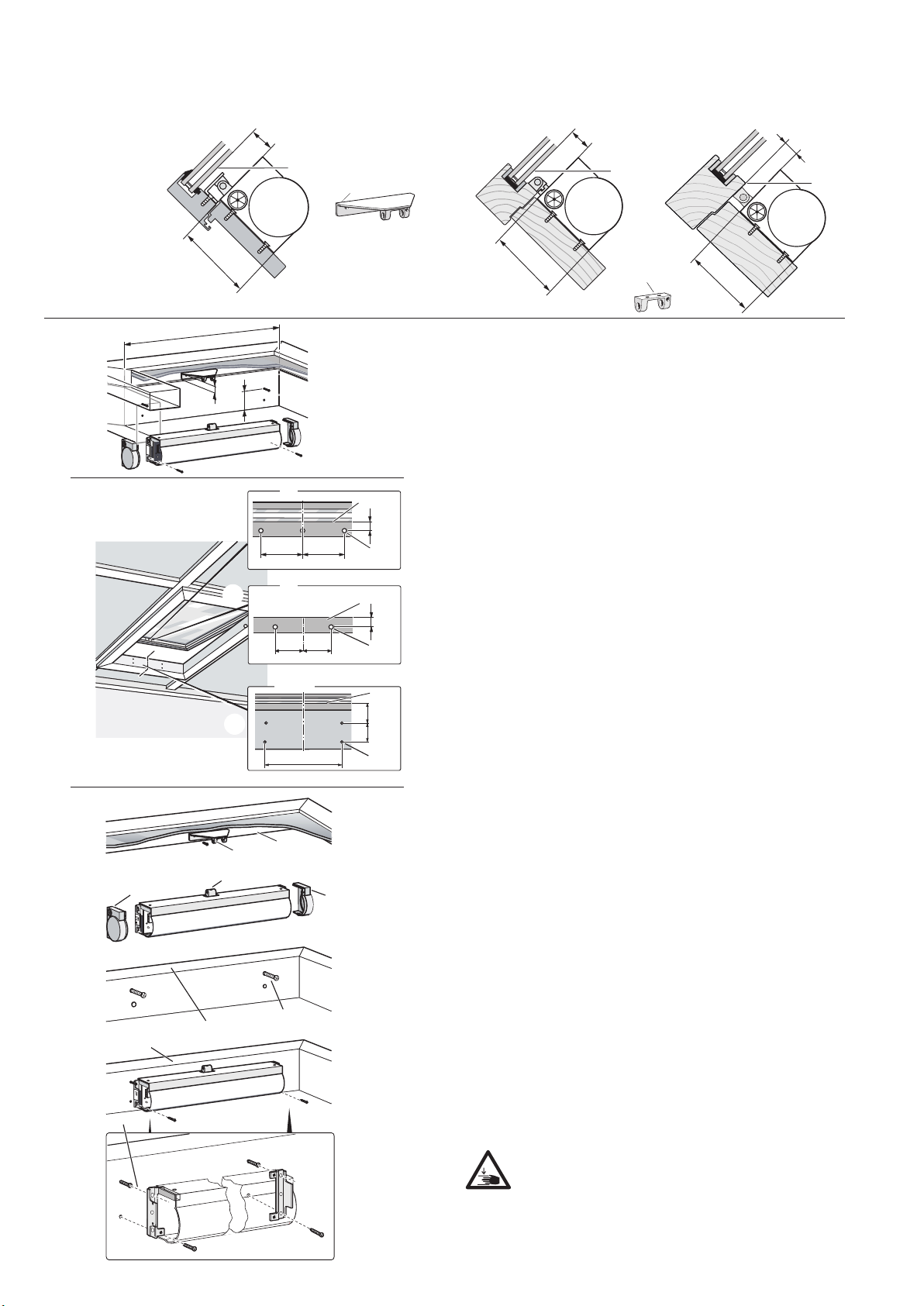
Stimmen Sie benötigtes Befestigungs-
material mit dem Baukörper und der
entsprechenden Belastung ab und ergänzen
Sie es, wenn nötig. Ein eventuell mitgelie-
fertes Befestigungs material entspricht nur
einem Teil der Erfordernisse.
The safety of personnel requires that
the following instructions be observed:
Declaration of Conformity/
state of the art
The drive has been constructed and tested
in conformity with all applicable European
directives. A corresponding declaration
of incorporation is available. You may not
operate the equipment unless a declaration of
conformity is available for the overall system.
The drive complies with the state of the
art and requires qualified personnel for
installation, maintenance, etc.
Personnel
The professional installation, maintenance,
repair and disassembly of the drive must be
entrusted to trained electricians as specified
in DIN VDE 1000-10!
Intended use
The motor is only suitable for the automatic
opening and closing of tilt, outward
opening, turn windows and skylights as well
as a smoke outlet and for ventilation.
Follow the technical specifications (in
particular, the opening cross section of
the window, the opening time and speed,
the temperature resistance of cables and
devices, and wind loads) as well as all
applicable regulations. Consult our factory
for any additional applications.
Select the required mounting material in
accordance with the structure and the
respective load and use additional mounting
material if necessary. Any included mounting
material will only correspond to parts of the
required material.
Certificates and declarations
HAUTAU declares that the drive is an incomplete machine in line
with the European Machinery Directive (2006/42/EC).
The Declaration of Incorporation is available via the QR code.
The following legislation have been applied:
- Machinery Directive 2006/42/EC
- EMC Directive 2014/30/EU
- RoHS Directive 2011/65/EU
HAUTAU erklärt, dass der Antrieb eine unvoll ständige
Maschine im Sinne der europäischen Maschinenrichtlinie
(2006/42/EG) ist.
Die Einbauerklärung ist über den QR-Code abrufbar.
Folgende Rechtsvorschriften wurden angewandt:
- Maschinenrichtlinie 2006/42/EG
- EMV-Richtlinie 2014/30/EU
- RoHS-Richtlinie 2011/65/EU
Zertifikate und Erklärungen

3
WARNUNG:
Wichtige Sicherheitsanweisungen! (Forts.)
WARNING:
Important safety instructions! (cont‘d)
Alle nicht dem bestimmungsgemäßen
Gebrauch entsprechenden Einsatzfälle oder
Änderungen am Antrieb sind ausdrücklich
verboten. Bei Nichteinhaltung übernimmt
HAUTAU keinerlei Haftung für Schäden an
Personen oder Material.
Aufbewahrung von Dokumenten/
Einweisung
Bewahren Sie diese Montageanleitung für
den späteren Gebrauch und die Wartung auf.
Händigen Sie die Bedienungsanleitung dem
Endanwender aus und nehmen Sie eine
Einweisung vor.
Installation und Bedienung
Vor der Montage: In der festverlegten
Installation ist eine Trennvorrichtung zur
Sicherstellung des allpoligen Abschaltens
vom Netz vorzusehen.
Fenster und Sicherheitselemente testen.
Die Unversehrtheit und Leichtgängigkeit des
Fensters sind sicherzustellen.
Vor dem Einbau des Antriebs muss der Instal-
lateur prüfen, ob der geltende Temperatur-
bereich auf die Umgebung abgestimmt ist.
Beim Betätigen eines Totmann-Schalters
dürfen sich keine weiteren Personen im
Umfeld des Antriebs aufhalten.
Bei RWA-Anlagen müssen beim Schließen
der Fenster Personen von den Fenstern
ferngehalten werden.
WARNUNG: Schließen Sie die Antriebe/
Bedienstellen nie an 230 V AC an!
Sie sind für 24 V gebaut! Der Antrieb
darf nur mit Sicherheitskleinspannung
(SELV) betrieben werden.
Andernfalls besteht Lebensgefahr!
ACHTUNG: Falls Sie die Arbeits-
schritte nicht beachten, führt dies zur
Zerstörung des Antriebs. Falsche
Handhabung gefährdet das Material.
Lassen Sie keine Flüssigkeit ins
Geräteinnere gelangen!
Any individual applications or modifications
of the drive which are not in compliance
with intended use are explicitly prohibited.
HAUTAU shall not be liable for any damage
to personnel or material resulting from
non-compliance with this provision.
Storing documents/instructions
Store these instructions for future reference
and maintenance. Make these installation
instructions available to the end user and
provide instructions.
Installation and operation
Prior to installation: A disconnecting device
must be provided in the fixed installation to
ensure mains disconnection at all poles.
Test window and safety elements.
The physical integrity and smooth operation
of the window must be ensured.
Before installing the drive, the installer must
verify that the drive‘s temperature range has
been adapted to its operating environment.
No other persons are allowed in the vicinity
of the drive when the deadman switch is
actuated.
Smoke and heat exhaust systems require
that people be kept away from the windows
when they are being closed.
WARNING: Never connect the
drives/control sections to 230 V AC
of voltage! They have been designed
to work with 24 V! The drive may only
be operated at safety extra low
voltage (SELV). Otherwise, there is
risk of death!
CAUTION: Failure to follow the work
steps will destroy the drive. Improper
handling endangers the material.
Do not allow any liquid to enter the
interior of the device!

4
WARNUNG: Der Antrieb öffnet und
schließt Fenster automatisch. Er stoppt
über eine Lastabschaltung.
Die Druckkraft reicht dennoch aus,
um bei Unachtsamkeit Finger zu
zerquetschen. Greifen Sie bei laufendem
Antrieb nicht in den Fensterfalz und nicht
in den Antrieb!
Quetsch- und Scherstellen zwischen
Fensterflügel und Rahmen, Lichtkup-
peln und Aufsetzkranz müssen bis zu
einer Höhe von 2,5 m durch Einrich-
tungen gesichert sein, die bei Berüh-
rung oder Unterbrechung durch eine
Person die Bewegung zum Stillstand
bringen (Richt linie für kraftbetätigte
Fenster, Türen und Tore der Berufs-
genossenschaften BGR 232).
Zur Vermeidung einer Fehlanwendung
ist am Einbauort eine Risikobeurteilung
nach Maschinenrichtlinie 2006/42/EG
erforder lich. Schutzmaßnahmen sind nach
EN 60335-2-103/2016-05 anzuwenden.
Hinweis:
Zum Betrieb des Antriebs ist ein
zusätzliches Bedien element (z. B.
Doppeltaster) notwendig.
Betreiben Sie die Antriebe nur mit
Steuerungen vom gleichen Hersteller.
Bei Verwendung von Fremdfabrikaten
keine Haftung, Gewähr- und Service-
leistungen.
Ein zuverlässiger Betrieb und das
Vermeiden von Schäden und Gefahren
sind nur bei sorgfältiger Montage/Einstel-
lung nach dieser Anleitung gegeben.
Benötigen oder wünschen Sie Ersatz-
teile oder Erweiterungen, verwenden
Sie ausschließlich Original -Ersatzteile.
WARNUNG:
Wichtige Sicherheitsanweisungen! (Forts.)
WARNING:
Important safety instructions! (cont‘d)
WARNING: The drive opens and
closes windows automatically.
It is stopped by overload cutoff.
However, the compressive force is
sufficient to crush fingers if you act
carelessly. Do not reach into the
window rebate or the drive while the
drive is running!
Crush and shear points between
window sashes and frames, light
domes, and metal curb must be
secured up to a height of 2.5 m by
devices that will stop the movement
by the touch or interruption of a
person (guideline BGR 232, issued
by the government safety organisa-
tion for power-controlled windows,
doors, and gates).
To avoid misuse, a risk assessment
acc. to Machinery Directive 2006/42/EC
is required at the installation site. Protective
measures are to be applied acc. to
EN 60335-2-103/2016-05.
Note:
Operation of the drive requires an
additional control (e. g. double
pushbutton).
Use the drives only in combination
with controls made by the same
manufacturer.
No liability will be accepted and no
guarantee nor service is granted
if products made by outside
manufacturers are used.
Reliable operation without any
damage and hazards requires that
installation/setup be made carefully in
accordance with these instructions.
If spare parts or extension compo-

5
Dieses Gerät kann von Kindern ab 8 Jahren
und darüber sowie von Personen mit
verringerten physischen, sensorischen
oder mentalen Fähigkeiten oder Mangel
an Erfahrung und Wissen benutzt werden,
wenn sie beaufsichtigt oder bezüglich des
sicheren Gebrauchs des Gerätes unter wiesen
wurden und die daraus resultierenden
Gefahren verstehen. Kinder dürfen nicht
mit dem Gerät spielen. Reinigung und
Benutzer-Wartung dürfen nicht von Kindern
ohne Beaufsichtigung durchgeführt werden.
Bei Anwendungen am Kippfenster
müssen Sie Kippfang-Sicherungsscheren
einbauen. Sie verhindern Schäden, die bei
unsachgemäßer Montage und Handhabung
auftreten können.
Bitte beachten Sie: die Kippfang-Sicherungs-
scheren müssen mit dem Öffnungshub des
Antriebes abgestimmt sein. Das heißt, die
Öffnungsweite der Kippfang-Sicherungs-
scheren muss, um eine Blockade zu vermei-
den, größer als der Antriebshub sein.
Prüfung
Überprüfen Sie nach der Installation und
nach jeder Veränderung der Anlage alle
Funktionen durch Probelauf.
Wartung/Instandhaltung
Die Stromzufuhr zum Gerät muss allpolig
unterbrochen werden, wenn Reinigungs-
oder andere Wartungsarbeiten durchgeführt
werden. Die Anlage ist gegen unbeabsichtig-
tes Wiedereinschalten abzusichern.
Die Fenster und Antriebe müssen regelmäßig
auf Unversehrtheit überprüft werden.
Bei Unwucht sowie Anzeichen von Verschleiß
oder Beschädigungen z. B. an Kabeln,
Splinten und dem gesamten Beschlag ist
der Antrieb nicht mehr zu verwenden, falls
Reparaturen oder Einstellungen erforderlich
sind.
Werden die Antriebe in Rauch- und Wärme-
abzugsanlagen (kurz RWA) eingesetzt,
müssen sie mindestens einmal jährlich
geprüft und gewartet werden. Bei reinen
Lüftungsanlagen ist dies auch zu empfehlen.
WARNUNG:
Wichtige Sicherheitsanweisungen! (Forts.)
WARNING:
Important safety instructions! (cont‘d)
nents are required or desired, use
only original spare parts.
This device may be used by children age 8
and older as well as all persons with limited
physical, sensory or mental abilities or lack
of experience and knowledge provided they
act under supervision or have received prior
instructions on the safe use of the device
and any hazards resulting from using the
device. Children are not allowed to play with
the device. Cleaning and user maintenance
must not be carried out by children without
supervision.
Applications on tilt windows require the
installation of scissor-type safety catches.
They prevent damage caused by incorrect
assembly and handling.
Please note: the scissor-type safety catches
must be adapted to the opening stroke
of the drive. This means that the opening
width of the scissor-type safety catches
must be larger than the drive stroke in order
to prevent blocking.
Testing
When installation is complete and after any
changes to the system, check all functions
by a trial run.
Maintenance/repair
The power supply to the device must be
interrupted at all poles for the duration of
any cleaning or other types of maintenance
operations. The system must be protected
against unintentional restarting.
Windows and drives must be checked for
physical integrity on a regular basis.
The drive must no longer be used in case
repairs or settings are needed if there is
unbalance or signs of wear or damage to
parts such as cables, split pins or the entire
hardware fitting.
If the equipment is employed in smoke and
heat exhaust systems (in short SHE), they
must be checked, serviced and, if required,
repaired at least once per year. This is also
recommended for pure ventilation systems.

6
Caution: Risk of crushing/trapping fingers! Do not
put fingers between sash and frame.
Hinweis bzgl. Befestigung Note concerning fixing
Vorsicht: Quetsch- u. Klemmgefahr! Finger
nicht zwischen Flügel und Rahmen halten.
Verwenden Sie stets die passenden Schrauben.
Schraubenauszugswerte gemäß Richtlinie TBDK:
Befestigung tragender Beschlagteile von Dreh- und
Drehkipp-Beschlägen. Internet: www.HAUTAU.de
Always use appropriate screws.
Screw pull-out values acc. to TBDK directive:
Attachment of supporting fitting components for turn-only
and tilt&turn fittings. Internet: www.HAUTAU.de
Die Geräte von Verunreinigungen befreien.
Befestigungs- und Klemmschrauben auf
festen Sitz prüfen.
Die Antriebe durch Probelauf testen.
Das Motorgetriebe ist wartungsfrei. Defekte
Antriebe dürfen nur in unserem Werk instand
gesetzt werden. Werden die Antriebe geöffnet,
führt dies zu Garantieverlust und Gewähr-
leistungsausschluss.
Es dürfen nur Original -Ersatzteile eingesetzt
werden. Die Betriebsbereitschaft ist regel-
mäßig zu prüfen.
Alle serienmäßig mit der RWA-Steuer zentrale
gelieferten Akkus bedürfen einer regelmäßi-
gen Kontrolle im Rahmen der Wartung und
sind nach der vorgeschriebenen Betriebszeit
(ca. 4 Jahre) auszutauschen.
WARNUNG:
Wichtige Sicherheitsanweisungen! (Forts.)
WARNING:
Important safety instructions! (cont‘d)
Pflege
Alle Geräte und Kabelanschlüsse auf äußere Beschädi-
gung und Verschmutzung prüfen. Rauchabzüge, Zentralen,
Feuertaster, Lüftungstaster usw. dürfen nicht in ihrer Funkti-
onstüchtigkeit,
z. B. durch bauliche Maßnahmen oder Lagergut, beein-
trächtigt werden.
Für die Reinigung der Gehäuseteile verwenden Sie ein
weiches, leicht befeuchtetes Tuch. Um eine Beschädigung
der Gehäuseoberfläche zu vermeiden, verwenden Sie für
die Reinigung keine ätzenden Chemikalien, aggressiven
Reingungslösungen oder lösungsmittelhaltigen Mittel.
Schützen Sie den Antrieb dauerhaft vor Wasser/Schmutz.
Gewährleistung
Für den Antrieb gelten die Allgemeinen Geschäftsbedingungen
(AGB) der Fa. HAUTAU (Internet: www.HAUTAU.de).
Entsorgung
Für Länder der Europäischen Union:
Führen Sie dieses Gerät nach der Verwendung
einer getrennten Müllsammlung zu. Entsorgen Sie
den Antrieb nicht über den unsortierten Hausmüll.
Care
Check all devices and cable connections for external
damage and dirt. The operability of smoke outlets, central
control units, fire pushbuttons, ventilation pushbuttons, etc.
must not be affected by, for example, structural measures
or stored goods.
Use a soft, slightly dampened cloth to clean the housing
components. To prevent damage to the housing surface,
do not use any caustic chemicals, abrasive cleaners or
agents containing solvents for cleaning. Provide the drive
with durable protection against water and dirt.
Warranty
The drive is subject to HAUTAU’s Terms and Conditions
(TC) (Internet: www.HAUTAU.de).
Disposal
For countries within the European Union:
When finished using the device, dispose of the
device by transferring it to separate waste collection.
Do not dispose of the drive along with unsorted
household waste.
Free the equipment from any contamination.
Check the tightness of fixing and clamping
screws.
Test the drives by trial run. The motor control
gear is maintenance free. Defective drives
must be repaired at our factory. Opening the
drives will result in loss of guarantee and
exclusion of liability claims.
You may only use original spare parts. The
readiness for operation has to be checked
regularly.
All batteries provided with the SHE control
panel need to be regularly checked as part
of the maintenance programme and have to
be replaced after their specified service life
(approx. 4 years).

7
Technische Daten Technical Data
Eingangs-/ 24 V DC (-10% / +25%)
Betriebsspannung
max. Stromaufnahme ca. 1,6 A (SKA 50-700: 1,2 A)
Druck-/Zugkraft SKA 50-500: max. 500 N
SKA 50-600: max. 500 N
SKA 50-700: max. 300 N
Zuhaltekraft 3000 N
Hublängen in mm SKA 50-500: 501 mm
SKA 50-600: 600 mm
SKA 50-700: 700 mm
elektrischer Anschluss 2-polige Steckschraubklemme
Abschaltung integrierte Endschalter AUF + ZU,
mit Sicherheitsüberlast-
abschaltung AUF + ZU
Laufzeit ca. 10 Sek. / 100 mm Hub
Einschaltdauer 60 Sek. (ED/ON)
180 Sek. (AD/OFF)
Schutzart IP 20 nach DIN 40050
Schutzklasse Klasse III nach DIN EN 61140
(VDE 0140-1)
Umgebungstemp. ca. -10 °C bis +60 °C
Ausstellmechanik Nirostahl-Doppelkette,
Reißverschlussprinzip
Gehäusematerial Aluminiumprofil
Farbe Silbergrau RAL 9006,
pulverbeschichtet
Sonderfarben Weiß RAL 9016 und auf Anfrage
nach RAL-Farbtafel
Endkappen Kunststoff, schwarz
Abmessungen (mm) SKA 50-500: 100,5 x 66 x 643
(B x H x L) SKA 50-600: 100,5 x 66 x 744
SKA 50-700: 100,5 x 66 x 846
Min. Flügelhöhe SKA 50-500: 800 (500*) mm
(* mit Kippkonsole) SKA 50-600: 1000 (600*) mm
SKA 50-700: 1100 (700*) mm
Lebensdauer 10.000 Zyklen Auf / Zu
Ein funktionssicherer Betrieb ist bei Anschluss an entsprechende
HAUTAU-Steuerungen gewährleistet. Bei Betrieb an Steuerungen von
Fremdherstellern ist eine Konformität auf Funktionssicherheit anzufragen.
Input/operating voltage 24 V DC (-10% / +25%)
power comsumption 1,6 A (SKA 50-700: 1,2 A)
Pressing/tractive force SKA 50-500: max. 500 N
SKA 50-600: max. 500 N
SKA 50-700: max. 300 N
Clamping force 3000 N
Stroke lengts in mm SKA 50-500: 501 mm
SKA 50-600: 600 mm
SKA 50-700: 700 mm
Electr. connection 2-pole plug-in screw terminal
Cut-off integrated limit switch “open”
and “closed” with safety overload
cut-off “open” and “closed”
Operating time approx. 10 sec. / 100 mm stroke
Start-up time 60 sec. (ED/ON)
180 sec. (AD/OFF)
Protective system IP 20 acc. to DIN 40050
Protective class Class III acc. to DIN EN 61140
(VDE 0140-1)
Range of temperatures approx. -10 °C to +60 °C
Hook-out machanics double chain according to the
zipper principle
Housing material aluminium profile
Colour silver grey RAL 9006,
powdercoated
Special colours white RAL 9016 and on request
to RAL-colour card
End caps plastic, black
Dimensions (mm) SKA 50-500: 100,5 x 66 x 643
(W x H x L) SKA 50-600: 100,5 x 66 x 744
SKA 50-700: 100,5 x 66 x 846
Min. sash height SKA 50-500: 800 (500*) mm
(* with tilt console) SKA 50-600: 1000 (600*) mm
SKA 50-700: 1100 (700*) mm
Lifespan 10.000 Open/Closed cycles
Trouble-free and safe operation is only warranted when used in con junc-
tion with an appropriate HAUTAU control unit. Request a technical
conformity declaration from the manufacturer of an alternative control
unit to ensure trouble-free and safe operation.
Besonderheiten
• automatisches Abschalten beim Erreichen der
Endposition (Auf und Zu)
• Überlastschutz
• mechanisch einstellbarer Dichtschluss
• Ausstellmechanik mit Doppelkette nach dem
Reißverschlussprinzip
• äußere Teile korrosionsfrei
• TÜV-Bauart geprüft
Features
• automatic switch off when end stop is reached
(Open and Closed)
• overload protection
• mechanical adjustable closing pressure
• opening mechanics with double chain according to the
zipper principle
• corrosion-free external elements
• TÜV type approved
34
5
7
6
2
2
1
B
A
A2
P1
B
C
Lieferumfang | Included in delivery
Lieferumfang included in delivery
1 Kettenantrieb chain drive
2 Klebestreifen self-adhesive pads for
(KF-Montage) bottom-hung open in
windows (KF mounting)
3 Befestigungsstift packer pin
4 Flügelbock hinge bracket
5 Gewindestift grub screw
6 Innensechskant- allen keys
schlüssel
Zubehör für DF-Montage (separate Bestellung):
Accessories for skylight mounting (please order in addition):
7 Flügelplatte coupling plate

8
A2
B
C
C
B
A1
A1 P1 A2 P1
A2
P1
B
C
A2
P1
B
C
3
3
4 **
1*
2
2
3
3
4 **
1*
Varianten
Options A1 Montage mit Flügelplatte
mounting with coupling plate
A2 Montage mit Flügelbock
mounting with hinge bracket
Montage am Dachfenster Mounting on skylight
5
4
6
7
6
89
9
8
A
B
C
1
1
2
3
4
5
6
7
37,5 37,5 Ø 3,6
17
P1
99
P1
17
38
50
P1
X
A1
A2
A1/A2
Ø 3,6
Ø 3,6
Mindestabstände beachten
Check minimum spacings
P1 = Bezugspunkt! Reference Point!
A = 700 mm (SKA 50-500)
A = 800 mm (SKA 50-600)
A = 910 mm (SKA 50-700)
B = 105 mm Auflagefläche des Antriebs
supporting surface drive
C = 25 mm Freiraum für Flügelbock
clearance for hinge bracket
Anreißen
Positioning
1 Mitte des Fensterflügels markieren, Löcher für
Flügel-platte A1 und Flügelbock A2 anreißen und
bohren. Mindestmaße beachten!
1 Mark the centre of the casement, mark and drill the
holes for the coupling plate A1 and hinge bracket A2.
Note minimum dimensions requirements!
2 Mitte des Rahmens markieren, Löcher für Antrieb
anreißen und bohren.
2 Mark centre of frame, mark and drill holes for drive.
X = 617 mm (SKA 50-500)
X = 718 mm (SKA 50-600)
X = 820 mm (SKA 50-700)
Anschrauben
Attaching
3 Flügelbock/-platte 4 an Fensterflügel 5 anschrauben.
3 Screw hinge bracket/coupling plate 4 on casement 5.
4 Endkappen 6 vom Antrieb entfernen und Ketten-
kuppler 7 anschrauben.
4 Remove end caps 6 from drive and screw on chain end
coupling 7.
5 + 6 Obere Schrauben 9 für den Antrieb
ein paar Umdrehungen in Fensterrahmen 8
einschrauben.
5 + 6 To attach the drive, first screw upper screws 9
a few turns into the window frame 8.
7 Antrieb an oberen Schrauben 9 einhängen und alle
vier Schrauben festziehen.
7 Suspend drive by upper screws 9, insert the two
remaining screws and then tighten all four screws.
Vorsicht: Verletzungsgefahr durch herunter-
schlagendes Fenster!
Caution: Risk of injury if the window falls down!
53

9
Montage am Kippfenster Mounting on bottom-hung open in window
B
A
D
B
D
12,5 Ø 5,2
X
Ø 3,6
9,5
18
1
2
1
2
3
4
+24V
GND
GND
+24V
auf
zu
5
4
6
+24V
GND
GND
+24V
auf
zu
7
+24V
GND
GND
+24V
auf
zu
4
1
3
2
4
5
6
7
8
9
D ≥ 6 mm und D < 18 mm: Unterlegplatte verwenden
D ≥6 mm and D < 18 mm: use packer
Mindestabstände beachten
Check minimum spacings
1 + 2
A = 700 mm (SKA 50-500)
A = 800 mm (SKA 50-600)
A = 910 mm (SKA 50-700)
B = 25 mm
D = 18 mm
Anreißen
Positioning
3 Mitte des Fensterflügels markieren, Löcher 1 für
Flügelbock anreißen und bohren.
3 Mark the centre of the casement, mark out and drill
hols 1 for hinge bracket.
4 Mitte des Rahmens markieren, Löcher 2 für Antrieb
anreißen und bohren. Abstand X kontrollieren.
4 Mark the centre of the frame, mark out and drill holes
2 for the drive. Check distance X.
X = 583 mm (SKA 50-500)
X = 684 mm (SKA 50-600)
X = 786 mm (SKA 50-700)
Anschrauben
Attaching
5 Flügelbock 2 an Fensterrahmen 1 anschrauben.
5 Screw hinge bracket 2 onto the window frame 1.
6 + 7 Endkappen 3 vom Antrieb 4 entfernen und
Kettenkuppler 5 anschrauben.
6 + 7 Remove end caps 3 from drive 4 and screw on
chain end coupling 5.
8 Antrieb 4 an Fensterflügel 6 anschrauben.
8 Screw drive 4 onto casement 6.
9 Klebestreifen 7 auf Antrieb 4 befestigen.
9 Fix self-adhesive pads 7 on drive 4.
Vorsicht: Verletzungsgefahr durch herunter-
schlagendes Fenster! Montieren Sie
Fangscheren, wenn keine vorhanden sind.
Caution: Risk of injury if the window falls down!
Fit a shear arm if not already fitted.

10
Montage mit Kippkonsole (am Kippfenster einwärts)
Mounting with tilt console (on bottom-hung open in window)
a
SKA 50-500: 624
SKA 50-600: 725
SKA 50-700: 827
18
Flügel
Sash
Flügel
Sash
Zwischenstück
Spacer
Zwischenstück
Spacer
107
min. 18
max. 90
max. 90
Blendrahmen
Frame
Blendrahmen
Frame
15
d
19
107
min. 18
15
d
19
a = 19,5
a = 28,5
19,5
28,5
Flügelhöhe SKA ... / sash height SKA ... a d
50-500 50-600 50-700
500 ... 649 600 ... 799 700 ... 899 28,5 41
650 ... 799 800 ... 999 900 ... 1099 19,5 32
Flügel / Sash
Flügel / Sash
Max. Profilstärke: 90 mm
Max. profile thickness: 90 mm
Zubehör (separate Bestellung):
Accessories (please order in addition):
1 Zwischenstück / spacer
2 Kippkonsole / tilt console
3 Zylinderschrauben M5 x 12
cylinder head screws M5 x 12
4 Mutter M5 (* nicht erforderlich bei a = 28,5)
nut M5 (* not required in case of a = 28,5)
Oberkante Flügel
Top edge sash
A2
B
C
C
B
A1
A1 P1 A2 P1
A2
P1
B
C
A2
P1
B
C
3
3
4
**
1*
2
2
3
3
4 **
1*
14*
4*
1

11
Fensterantrieb anschließen | Connecting window drive
5
X
34
6
7
3
1
2
3
A
B
L
N
1
1
2
3
4
+24V
GND
GND
+24 V Zu
Closed
1
Auf
Open
5
X
34
6
7
3
1
2
3
A
B
L
N
1
1
2
3
4
+24V
GND
GND
+24 V Zu
Closed
1
Auf
Open
Vorsicht: Verletzungs- oder Lebensgefahr
durch einen Stromschlag!
Caution: Risk of injury or death from electric
shock!
Vorsicht: Verletzungsgefahr durch Quetschen
von Hand oder Fingern!
Caution: Risk of injury by crushing hands or
fingers!
Achtung: Lassen Sie alle elektrischen
Anschlüsse von einer Elektrofachkraft durch-
führen!
Attention: Ensure that all connections are carried
out by a qualified electrician!
Achtung: 24 V - Anschluss.
Attention: 24 V - connection.
Anschließen
Connecting
1 2-adriges Anschlusskabel (2 x 1 mm² Querschnitt)
erforderlich. Oder mit Leitungsüberwachung ein
3-adriges Kabel. Dachfenster anheben/Kippfenster
sichern, Antrieb anschließen.
1 A two-core connection cable (cross-section 2 x 1 mm²)
is required, or if a line-monitor is fitted, a three-pole
cable. Lift up skylight / secure bottom-hung open in
window, connect drive.
Dichtschluss einstellen
Adjusting closing pressure
2 Fenster 5 schließen, Kette ganz einfahren und
Abstand X zwischen Kettenkuppler 4 und Flügel-
platte/-bock 3 messen.
2 Close window 5, retract chain completely and measure
distance X between chain and end coupling 4 and hinge
bracket 3.
3 Endabschaltung entsprechend des Wertes X
einstellen. Eine Umdrehung des Schlüssels 6
entspricht einem Millimeter.
3 Set limit switch according to value X. One turn of the
key 6 corresponds to one millimetre.
4 Kette 10 cm ausfahren, Kettenkuppler 7 mit Flügel-
bock 3 verbinden.
4 Extend chain by 10 cm, connect chain end coupling 7 to
hinge bracket 3.
Hinweis: Leuchtet die Leuchtdiode 1 beim Einfah-
ren der Kette auf (Abschaltung durch
Über last), so muss der Dichtschluss neu
eingestellt werden.
Note: If the LED 1 lights up when retracting the chain
(switch off due to overload) the closing pressure
schould be re-adjusted.

HAUTAU GmbH | Wilhelm-Hautau-Str. 2 | 31691 Helpsen | Germany | Tel +49 5724 393-0 | info@hautau.de | www.hautau.de
This manual suits for next models
2
Table of contents
Other Maco DC Drive manuals
Popular DC Drive manuals by other brands

HAUTAU
HAUTAU SKA 30 Mounting and operating instructions

Danfoss
Danfoss VLT AutomationDrive FC 360 Application guide

Danfoss
Danfoss VACON OPTEA operating guide

Rockwell Automation
Rockwell Automation Allen-Bradley PowerFlex 6000 Commissioning manual

Johnson Controls
Johnson Controls VSD Series user manual

Carotron
Carotron Elite Pro Series instruction manual