MacroAir Technologies AirEffect User manual

Operation Manual
AirEffect


Table of Contents
© 2020 MacroAir Technologies Toll Free: 866 668 3247 Fax: 909 890 2313 www.macroairfans.com
AirEffect Operation Manual 90-30017-00 Rev A-01 Date: 031920
1
Introduction
Installation
Information
Caution & Safety, Electrical Guidelines ..........................2
Installation, Safety & Service .........................................3
AirEffect Sensor Installation ......................................... 4
T-Splice Connection Method ....................................... 6
AirEffect Setup.............................................................. 8
AirEffect Screen ............................................................ 9
Zone Setup Screen........................................................ 11
Technical Support..................................................... 12

2 Introduction
© 2020 MacroAir Technologies Toll Free: 866 668 3247 Fax: 909 890 2313 www.macroairfans.com
AirEffect Operation Manual 90-30017-00 Rev A-01 Date: 031920
Caution and Safety
This appliance can be used by children aged from eight (8) years and above and persons with
reduced physical, sensory, or mental capabilities or lack of experience and knowledge if they
have been given supervision or instruction concerning use of the appliance in a safe way and
understand the hazards involved.
Children shall not play with the appliance. Cleaning and user maintenance shall not be made by
children without supervision.
⚠ATTENTION: Safety.
READ AND SAVE THE ENTIRE MANUAL BEFORE OPERATING THE FAN.
Ensure that all safety procedures and instructions are followed during the installation, operation
and servicing of the fan. Failure to apply these safety practices could result in death or serious
injury. If you do not understand the instructions, please call our Technical department for
guidance.
⚠CAUTION: Non-Compliance. The fan installation should follow the recommendations
outlined in its accompanying fan manual. MacroAir is not responsible for any injury or damage
to persons or property because of ‘not complying’ with the recommendations outlined in the
manual.
Electrical Guidelines
⚠WARNING: Electrical Damage. Improper electrical installation can cause damage to the fan
and interfere with other electronic equipment. In addition to standard electrical safety
considerations, please observe the following:
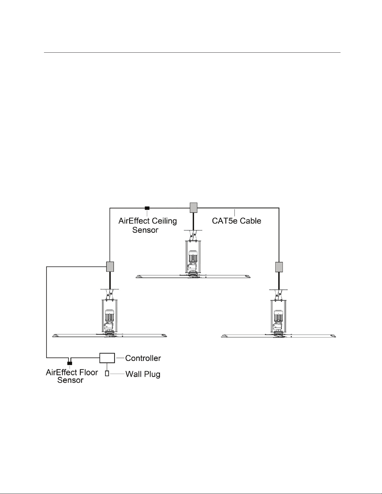
xMacroAir Cables. The wiring from the control panel to the fan MUST be MacroAir
supplied shielded cable. CAT5e to be MacroAir supplied twisted, stranded, and shielded
or greater.
xElectrical Interference. Separate incoming power and motor control cables by a
minimum of six (6) inches.
xRead. Please refer to the Controller 30 Manual for more information.
⚠ATTENTION: Qualified Technicians. All fan controls should only be installed by qualified
technicians familiar with the requirements of the National Electrical Code (NEC) and local codes.
Refer to appropriate portions of this manual for other important requirements. Failure to follow
these guidelines will void the manufacturer’s warranty.
⚠ATTENTION: Factory Configured. All electrical controls are configured at the factory and are
ready to use. No user adjustments are available. Follow the included wiring schematics and
installation instructions when installing this device to ensure proper operation. Do not make any
changes to any part of the motor control panel without first consulting MacroAir.

3 Introduction
© 2020 MacroAir Technologies Toll Free: 866 668 3247 Fax: 909 890 2313 www.macroairfans.com
AirEffect Operation Manual 90-30017-00 Rev A-01 Date: 031920
Electrical Guidelines, cont.
⚠ATTENTION: Read. Read and understand this manual before installing or operating AirEffect.
Installation, adjustment, repair, and maintenance must be performed by qualified personnel.
⚠ATTENTION: Code Compliance. The user is responsible for compliance with all international
and National Electrical Code requirements with respect to grounding of all equipment.
⚠WARNING: Covers. Install all covers before applying power.
Installation, Safety and Service
⚠WARNING: Damage. Do not operate or install any fans or fan accessories that appear to be
damaged.
⚠ATTENTION: Qualified Technicians. All electrical troubleshooting and repair must be done by
a qualified technician and meet all applicable codes.
⚠ATTENTION: Check Federal, State, and Local Codes. Check all relevant codes to make sure
that all product certifications, product listings, and building regulations are met. Code
compliance is the responsibility of the installer.
REFER TO FAN INSTALLATION MANUAL(S) FOR FURTHER MAINTENANCE INFORMATION.

4 Installation
© 2020 MacroAir Technologies Toll Free: 866 668 3247 Fax: 909 890 2313 www.macroairfans.com
AirEffect Operation Manual 90-30017-00 Rev A-01 Date: 031920
AirEffect Sensor Installation
⚠WARNING: Probe Mounting. Do not mount in such a manner that the temperature probe
rests on metal as it will then be reading the temperature of the metal rather than the air
temperature.
Note: Match the correct Zone “Floor” sensor with the correct Zone “Ceiling” sensor. Make sure
“Floor” is at the floor level (pg. 5, instruction 4) and “Ceiling” is at the ceiling level (pg. 4,
instruction 1).
Black (From Power Supply)........................Common
PINOUT: Black/White (From Power Supply) ...........24VDC+
Blue (From Cat5E) .......................................Net+
Blue/White (From Cat5E)...........................Net-
Mounting
1. Ceiling Mounting: Mount the ceiling temperature sensor at least 1ft [0.3 m] below the
ceiling in the same room where the fan/fans are placed. Use caution when placing the sensor
making sure not to place it where there is any contact with direct sunlight. Each sensor has
small mounting holes for attachment with screws.
2. Once the module has been placed it can be wired into the network. Use the provided
110/120V power supply to power the temperature sensor and the blue, blue/white, and
brown wires from the CAT5e cable for communication. If there is enough slack in the cable
you can run the wiring directly in and out at the same point on the sensor module.
3. Please refer to the wiring diagram. See pages 6-7 of this manual for proper stripping and bean
crimping of wires.

5 Installation
© 2020 MacroAir Technologies Toll Free: 866 668 3247 Fax: 909 890 2313 www.macroairfans.com
AirEffect Operation Manual 90-30017-00 Rev A-01 Date: 031920
AirEffect Sensor Installation cont.
4. Floor Mounting: Mount the floor temperature sensor within 6ft [1.8m] of the ground in the
room where the fan/fans are placed. Use caution when placing the sensor making sure not
to place it where there is any contact with direct sunlight. Each sensor has small mounting
holes for attachment with a screw.
5. Repeat steps 2-3 and refer to the wiring diagram.
6. If there is not enough wire to pull in and out of the sensor, splice a length of cable keeping
length to a minimum. Use the bean crimps supplied by Macro Air to wire the lead into the
network. Please refer to network wiring diagram. Note: The Brown/White wire is only used
to power a repeater. Do not terminate the Brown/White wire on the drive or t-splice
unless it is used to power one of these devices.
Proper sensor placement is shown below:

6 Installation
© 2020 MacroAir Technologies Toll Free: 866 668 3247 Fax: 909 890 2313 www.macroairfans.com
AirEffect Operation Manual 90-30017-00 Rev A-01 Date: 031920
Temp Sensor T-Splice Connection Method
1. Take the incoming CAT5e from the
network, the 15ft [4.57m] CAT5e whip
from the fan, and the CAT5e going to
the rest of the network. Give some slack
(no more than 2ft / 0.6m) on each
CAT5e to strip the wires and splice them
together. Run the slack up towards the
ceiling and back down in a horseshoe
shape.
DO NOT roll the excess slack into a circle or coil because this creates a place for the
network to pick up noise on the lines.
2. Strip jacketing off the three CAT5e
cables and separate each color wire
leaving approximately 2in [5cm] of each
wire exposed including the drain/shield
wire.
3. Strip approximately 1/2in [1.3 cm] off
each color wire leaving the bare copper
exposed.
4. Twist the 3 wires of same color from
each CAT5e together.

7 Installation
© 2020 MacroAir Technologies Toll Free: 866 668 3247 Fax: 909 890 2313 www.macroairfans.com
AirEffect Operation Manual 90-30017-00 Rev A-01 Date: 031920
Temp Sensor T-Splice Connection Method cont.
5. Place a gel filled bean crimp onto the end
of the 3 wires and use a small crimper or
pliers to crimp the bean tight on the
wires.
6. Double check that the 3 drain wire/bare
wires are also crimped together as this is
what continues the shielding throughout
the network. The shielding and drain wire
MUST be connected to Earth Ground at
only one point of the cable run.
7. Repeat steps 3-5 for all the wires EXCEPT
the Brown/White wire. The Brown/White
wire is only needed for wiring in a
repeater.
8. Once all the wires are crimped, carefully
twist the wires up. Then fold them back
and tape them up with electrical tape to
clean up your wiring.

8 Installation
© 2020 MacroAir Technologies Toll Free: 866 668 3247 Fax: 909 890 2313 www.macroairfans.com
AirEffect Operation Manual 90-30017-00 Rev A-01 Date: 031920
AirEffect Setup
In order for AirEffect to operate properly, some setup is required. Please follow the below steps
to ensure a smooth operation:
1. Ensure that the diameter is programmed on every fan’s Fan Configure Screen (Reference the
Controller 30 Manual).
2. Use the Zone Setup Screen to add or remove fans from the desired zone(s) (pg 11).
3. Once the zone is properly set up, input your minimum and maximum speeds for each fan.
Note that while all fans may be shown, you only need to input values for fans that are in the
zone.
4. Input the distance to the next fan or wall. If you have more than one distance, such as a fan
between two other fans, use the smaller value or an average of the distance. Check boxes
are available for you to specify whether the distance is to a fan or wall.
5. Input the roof height, fan height, and ground sensor height.
6. Under “Check Every”, specify the interval at which the system will rescan for changes to
temperature and humidity and make the appropriate adjustments.
7. Under “Desired Cool”, input the temperature at which you desire the fans to begin cooling
the space.
8. Under “Desired Heat”, input the temperature at which you desire the fans to begin warming
the space.
9. Under “Max Humidity”, input the percentage at which you desire the fans to circulate more
air, thereby lowering the humidity.
10. Once everything is set up, check the “Zone Enabled” box. This zone will now run according to
the parameters you specified.

9 Installation
© 2020 MacroAir Technologies Toll Free: 866 668 3247 Fax: 909 890 2313 www.macroairfans.com
AirEffect Operation Manual 90-30017-00 Rev A-01 Date: 031920
AirEffect Screen
If your network was ordered with the AirEffect option, the AirEffect control screen can be
accessed by tapping the “AirEffect” button. AirEffect allows your fans to run automatically based
on temperature, humidity, and user preferences, creating the most comfortable environment
possible.
1 Back - Takes you back to the previous screen.
2 Fan Name - Displays the name of the fan.
3 Minimum Speed (Default 0) - Sets the minimum speed the fan is allowed to operate at.
Useful if the fan is mounted high in the ceiling and effects cannot be felt below a certain speed.
4 Maximum Speed( Default 100) - Sets the maximum speed the fan is allowed to operate at.
Useful if running at high speeds causes undesired effects (ex. papers blowing or welding).
5 Distance to Nearest Fan/Wall - Specifies the distance from this fan to the next fan or a wall.
6 Zone Setup - Takes you to the zone setup screen.
7 Zone Settings - Allows you to select a zone to view/input data.
8 Zone Enabled - Checking this box enables AirEffect for the zone, unchecking this box
disables AirEffect for the zone and places the fans in manual mode.
9 Roof Height - Allows you to specify the distance between the floor and the roof of the zone.
10 Fan Height - Allows you to specify (or average) the height of the blades above the floor.
11 Sensor Height - Allows you to specify the height of the ground sensor (default 3ft [0.9m]
above floor).

10 Installation
© 2020 MacroAir Technologies Toll Free: 866 668 3247 Fax: 909 890 2313 www.macroairfans.com
AirEffect Operation Manual 90-30017-00 Rev A-01 Date: 031920
AirEffect Screen cont.
12 Check Every - Allows you to specify how often AirEffect will check for changes in the
environment and adjust accordingly.
13 Max Humidity - Allows you to set a desired maximum humidity as a condition for the fans
to run.
14 Roof Temp - Displays the temperature measured by the roof sensor.
15 Ground Temp - Displays the temperature measured by the ground sensor.
16 Ground Humid - Displays the humidity measured by the ground sensor.
17 Desired Cool - Allows you to set a temperature threshold that will cause AirEffect to cool
the environment.
18 Desired Heat - Allows you to set a temperature threshold that will cause AirEffect to warm
the environment.
19 Units are in ft and F - Displays the units currently being used on the screen. Press the
button to toggle between feet and Fahrenheit, or meters and Celsius.

11 Installation
© 2020 MacroAir Technologies Toll Free: 866 668 3247 Fax: 909 890 2313 www.macroairfans.com
AirEffect Operation Manual 90-30017-00 Rev A-01 Date: 031920
Zone Setup Screen
Pressing the “Zone Setup” button on the AirEffect screen will bring you to the zone setup page.
This page allows you to add or remove fans from zones. Multiple zones are useful if you have
fans in multiple rooms/environments that need to be run differently. Please note that two
sensors are required per zone.
1 Back - Takes you back to the AirEffect screen.
2 Zone Groups - Displays the zone groups.
3 Zone Members - Displays the fans when a zone group is selected. Check boxes to add fans
to the zone, uncheck boxes to remove them.
4 Accept - Saves any changes you made.
5 Cancel - Cancels any changes you made.

12 Information
© 2020 MacroAir Technologies Toll Free: 866 668 3247 Fax: 909 890 2313 www.macroairfans.com
AirEffect Operation Manual 90-30017-00 Rev A-01 Date: 031920
Technical Support
For installation assistance, application questions, technical support
& any other inquiries, please contact our Technical Support team at
(866) 668-3247 option 2.

794 South Allen Street
San Bernardino, CA 92408
(866) 668-3247
Macroairfans.com
Table of contents
Popular Accessories manuals by other brands

American Standard
American Standard FloWise Showerhead 1660.715 installation instructions

Sound Devices
Sound Devices USBPre 2 User guide and technical information

SGL
SGL LH-045MGR instruction manual

Leuze electronic
Leuze electronic IPS 248i Original operating instructions

Simrad
Simrad PI DEPTH Quick reference guide

ETC
ETC Echoflex Elaho installation guide

PCB Piezotronics
PCB Piezotronics WM106B Installation and operating manual

Victory
Victory VDW-24-4 manual

IFM Electronic
IFM Electronic efector300 SU9004 operating instructions

Evolution
Evolution PURE MINERALS LS70 Installation and operation manual

EVOline
EVOline FrameDock Customer's operating and assembly instructions

Smarteh
Smarteh LPC-2.SM7 user manual