MacuLogix AdaptDx Pro M-1 User manual

USER MANUAL
Model M-1
PRO-LBL-015 AdaptDx Pro User’s Manual Intl (Rev 2)
© 2020 MacuLogix, Inc.
PN: 10473 AdaptDx Pro User Manual, English-Intl

2 3
1. Introduction 3
2. Intended Use 3
3. Limitations of Use 3
4. Authorized European Representative 3
5. Essential Performance 3
6. Device Components and Operation 4
7. Cleaning 18
8. Troubleshooting 19
9. Customer Support 19
10. Repair 20
11. Disposal 22
12. Specications 22
13. Electrical Safety and EMC 24
14. Symbol ID 34
1. Introduction
Dark adaptation is the process of the eyes adjusting to low levels of illumination. During dark adaptation,
the sensitivity of the eye to light is increased. The two major components of dark adaptation are dilation
of the pupil and photochemical alterations of the retina.
The AdaptDx Pro™ device includes a headset that is worn over the eyes and a controller that is held
in the patient’s hand during a dark adaptation test. The patient dons the headset to create a complete
light seal and then is exposed to a bright ash followed by a dim adaptation stimulus. The intensity of the
adaptation stimulus is gradually extinguished. The just-detectable stimulus intensity and the time at which
it is detected are periodically recorded to generate a dark adaptation threshold curve. The speed of dark
adaption recovery is characterized by a proprietary parameter called the Rod Intercept,™ (RI™) which is
displayed as the result of the dark adaptation test.
2. Intended Use
The AdaptDx Pro is a battery-powered, head-mounted automated dark adaptometer intended
to evaluate the time for retinal adaptation after exposure to an adapting light. It is intended for use
as a diagnostic device to aid in the detection, monitoring, and management of age-related macular
degeneration (AMD) and for measurement of dark adaptation speed.
3. Limitations of Use
The AdaptDx Pro is not suitable for use with patients who are unable to follow simple instructions,
operate a response button, or maintain attention for the anticipated duration of the test. The AdaptDx
Pro is not suitable for use with patients who are unable to perform the Test Tutorial (See Section 6).
4. European Authorized Representative
Medspace Medical Devices BV +31 43 306 3320
Il Fiore Building B, 3rd Floor +31 43 306 3338
Avenue Ceramique 227
6221 KX Maastrich
The Netherlands
5. Essential Performance
When the AdaptDx Pro headset is properly connected to the handheld controller with the supplied
connection cable, the AdaptDx Pro has no features that would be deemed an unacceptable risk if it
malfunctions. Therefore, there is no essential performance associated with the AdaptDx Pro.
CONTENT
EC REP

4 5
6. Device Components and Operation
Familiarizing yourself with your AdaptDx Pro is the rst step in ensuring a smooth operation.
Here’s a road map:
Device Components and Accessories
• AdaptDx Pro Dark Adaptometer Headset
-Power Button
-Diopter Adjustment Knob
-Adjustable Overhead Strap
-Conforming Eyecups
-Activation Scanner for Comfort Guard™ hygienic eyecup covers
-Directional Speakers
• Handheld Controller with Rechargeable Battery (2)
• Wall Charger
• Controller Cable
• AdaptDx Pro Comfort Guard™ Hygienic Eyecup Covers (10 Pack)

6 7
Accessories and Reorder Part Numbers
• AdaptDx Pro Comfort Guard Hygienic Eyecup Covers (25 Pack) – Reorder # 10340
• AdaptDx Pro Comfort Guard Hygienic Eyecup Covers (10 Pack) – Reorder # 10339
• Adjustable Head Strap with Padded Liner – Reorder # 10384
• Padded Liner for Head Strap – Reorder # 10385
• Conforming Eyecups – Reorder # 10386
• Handheld Controller with Rechargeable Battery – Reorder # 10387
• Controller Cable – Reorder # 10388
• Wall Charger – Reorder # 10389
Operation
Your device comes inside this neatly packed box. Your accessories are located in a special blue drawer on
the bottom of the box. Look for the silver tab and pull to retrieve the accessories.
Make sure your device is fully charged prior to operation. Connect the handheld controller to the
USB-C wall charger and plug the charger into an electrical outlet. A solid green light will illuminate on
the handheld controller when the device is fully charged. Disconnect the handheld controller from the
charger. Plug the straight end of the USB-C cable into the handheld controller and the angled end of the
cable into the device. Lastly, you can start the device by holding down the AdaptDx Pro power button
until the green light turns on.
Get to Know Your Home Screen
First-time Use
You can enter your default settings when you turn on your AdaptDx Pro for the rst time. The device will
automatically default to the options selected the next time you turn on your device.
Via your handheld controller, select the “System Tools” icon on at the top of your screen. Use the
arrows on the left and right to scroll to the item you want to set or edit defaults.
Select language
Select the “System Tools” icon at the top of your screen. Scroll through setup options and choose “Select
Language.”

8 9
Use the arrows on the top or bottom of each item on the next screen to scroll through options
(up and down arrows) for user interface language and patient testing audio . Once you have
made your selections, navigate to the “System Tool” icon at the top of the screen to save
your settings.
Set up your wireless connection
Select the “System Tools” icon at the top of your screen. Scroll through setup options and choose “Select
Network.”
• If connectivity parameters have been completed, the connection will be shown on the screen.
• If no wireless connection has been established or to add a new connection
-Scroll through the available networks using the up and down arrows and choose the desired
network.
-Next, enter the network password by using the up and down arrows to select each character.
-Navigate to the “Enter” button to save the password.
Set date and time
Select the “System Tools” icon at the top of your screen. Scroll through setup options and choose “Set
Date/Time.”
• You can choose a time zone by scrolling through your options, using the up and down arrows.
Navigate to and choose the desired time zone.

10 11
• You can set the time by manually enter the time and date, by using the up and down arrows.
Select default eye and test
Click on the “System Tools” icon at the top of your screen. Scroll through setup options and choose the
“Edit Test Defaults” screen.
• Select the default test eye. The icon on the left side of the screen indicates the right eye and the
icon on the right side of the screen indicates the left eye.
• Set test type. The icon on the left side of the screen indicates the Rapid Test and the icon on the
right side of the screen indicates the Extended Test.
- The Rapid Test is a pass/fail protocol used to assess the patient’s dark adaptation function and
takes 2.5 to 6.5 minutes to complete. The Extended Test provides a detailed characterization
of the patient’s dark adaptation function and a benchmark for monitoring changes over time. The
Extended Test can take up to 20 minutes to complete, based on the severity of impairment.
For example, in this case:
- The default settings would be Left Eye, Rapid Test. You can change your default settings at any time
by selecting the “System Tools” on the home screen and repeating the process described above.
You can edit any of your default settings at any time. Simply select the “System Tools” icon at the top of
your screen and choose the item to be edited.

12 13
AdaptDx Pro in Action
The AdapDx Pro will run through a sequence of self-checks when you rst turn it on. Your screen will
display an error warning if corrective action is needed (e.g., connect the handheld controller to the
headset).
If an error is detected during self-check, you will be prompted to contact MacuLogix tech support and
supplied with reference data for your case.
Once the self-check has been completed, the AdaptDx Pro Home screen will be displayed, showing
your selected default settings. If you wish to proceed with these settings, select the blue button with the
white arrow at the bottom of the screen.
If you would like to use settings other than your defaults, select the “System Tools” icon at the top of
your screen and navigate to the item you would like to change. Use the left and right arrows to make
your selection. For example, if you wish to change the eye tested, navigate to the eye icon and use the
arrows on the left and right to scroll through your options.
Follow the same process to change test type if needed. (Click on the “timer” icon and use left and right
arrows to scroll through the options.)
Once you have selected the test eye and the test type, select the blue button with the white arrow at
the bottom of the screen.

14 15
Patient Preparation
Once the test eye and test type have been
selected, install a new pair of Comfort Guard
hygienic eyecup covers. Activate the eyecup covers
by holding the “L” tag to the symbol under the
headset for ve seconds (Figures 6.1– 6.2).
Once activated, place the Comfort Guard covers
over the eyecups, left and right side respectively
(Figure 6.3).
Once the system has veried that a new pair of Comfort Guard hygienic eyecup covers have been
installed, an animation will provide step-by-step instructions for how to t the headset on the patient and
how the diopter adjustment works.
Introduction
Theia™, the on-board technician, will introduce herself to the patient and will outline the basics of the
test. At the end of the introduction, the user will be given a brief tutorial in which the pupil xation will be
established and the pupil size will be measured.
Once the test starts, a progress bar will appear on the user interface to keep the technician abreast of
each step in the process.
Bleach Demonstration
Theia will ask the patient to look directly at the small red light in the center of their visual eld and will
instruct the patient to press the response button to verify when they see the a bright ash of light.
Stimulus Demonstration
Theia will ask the patient to look directly at the small red light in the center of their visual eld and instruct
the patient to press the button every time they see a spot of light in their peripheral vision. Once a
threshold has been detected, photobleaching will be initiated to begin measuring
dark adaptation.
Figure 6.2 Figure 6.3
Figure 6.1

16 17
Test Administration
Theia will inform the patient that the test is about to begin. The system will automatically nd and
measure the patient’s pupil, ash a bright light, and start the full test.
The threshold detection algorithm will initiate, and the display screen will indicate the test is underway.
Theia will automatically guide the patient through timed rest breaks. The progress bar will update after
each subsequent rest break occurs.
Upon test completion, the system will pause and display the “Test Complete” screen.
Loosen the adjustable headstrap using the dial and remove the headset from the patient’s head. Using
the handheld controller, the technician must now select the blue button with the white arrow on the
bottom of the screen to acknowledge test completion and move to the next step.
Results Review
• The Rod Intercept (RI) is the time in minutes at which the visual sensitivity recovery is complete.
• The Fixation Error is the percentage of times the patient generates invalid thresholds correlating to a
loss of focus on the xation light and an inappropriate response to the xation light.
• An invalid test will be generated if a patient blinks or averts their gaze during photobleaching,
resulting in dark adaptation that is faster than typically seen in properly bleached patients.
If powered down while on this screen, the unit will allow recovery of results upon reboot. The yellow
check denotes a forced view.

18 19
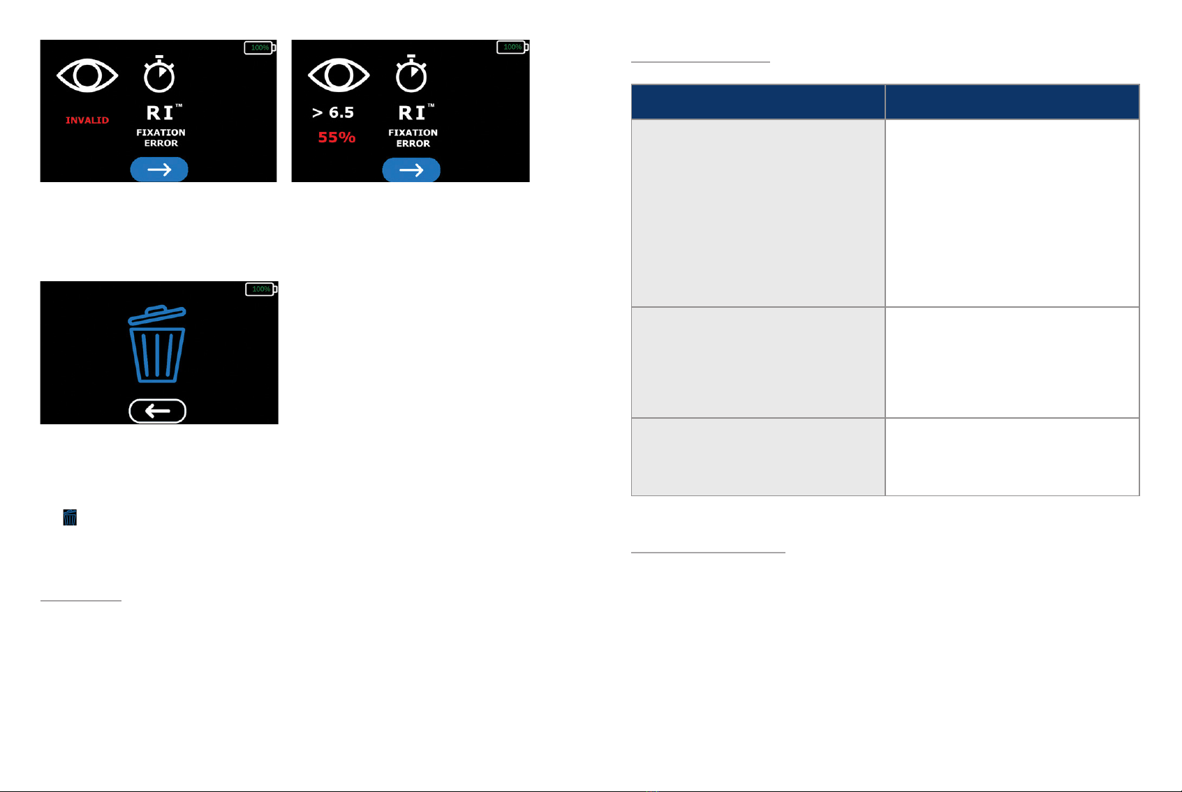
A warning will be generated if a bleaching error (INVALID) was detected or if the xation error is above
30%. A bleaching error or xation rate higher than 30% indicate the results are not valid and the patient
should be retested. After photobleaching, the test eye should not be retested for at least 30 minutes to
ensure a reliable test result.
The system will pause here until the technician has recorded the test results. If the system is powered
down while on this screen, it will automatically display the results the next time the system is booted. To
proceed to the conrmation screen, select the blue button with the white arrow at the bottom of the
screen. To return to the results screen, select the blue button with the white arrow under the “delete”
icon . To conrm the results have been successfully recorded, navigate to and select the “delete” icon.
The results must be deleted before proceeding to another test.
7. Cleaning
Never immerse the AdaptDx Pro in water or other uids, spray, pour or spill liquid onto the AdaptDx
Pro, its accessories, connections, or openings in the device. Dry any liquid on the surface of the device
immediately.
Required cleaning includes regular swabbing of the patient contact points and removal of debris from view
windows, plus periodic cleaning of the display screen. The patient contact points (rubber eyecups, padded
liner, adjustable headstrap, handheld controller) should be wiped between each patient. The use of isopropyl
wipes is recommended. View windows should be gently cleaned with a lens cloth and/or compressed air.
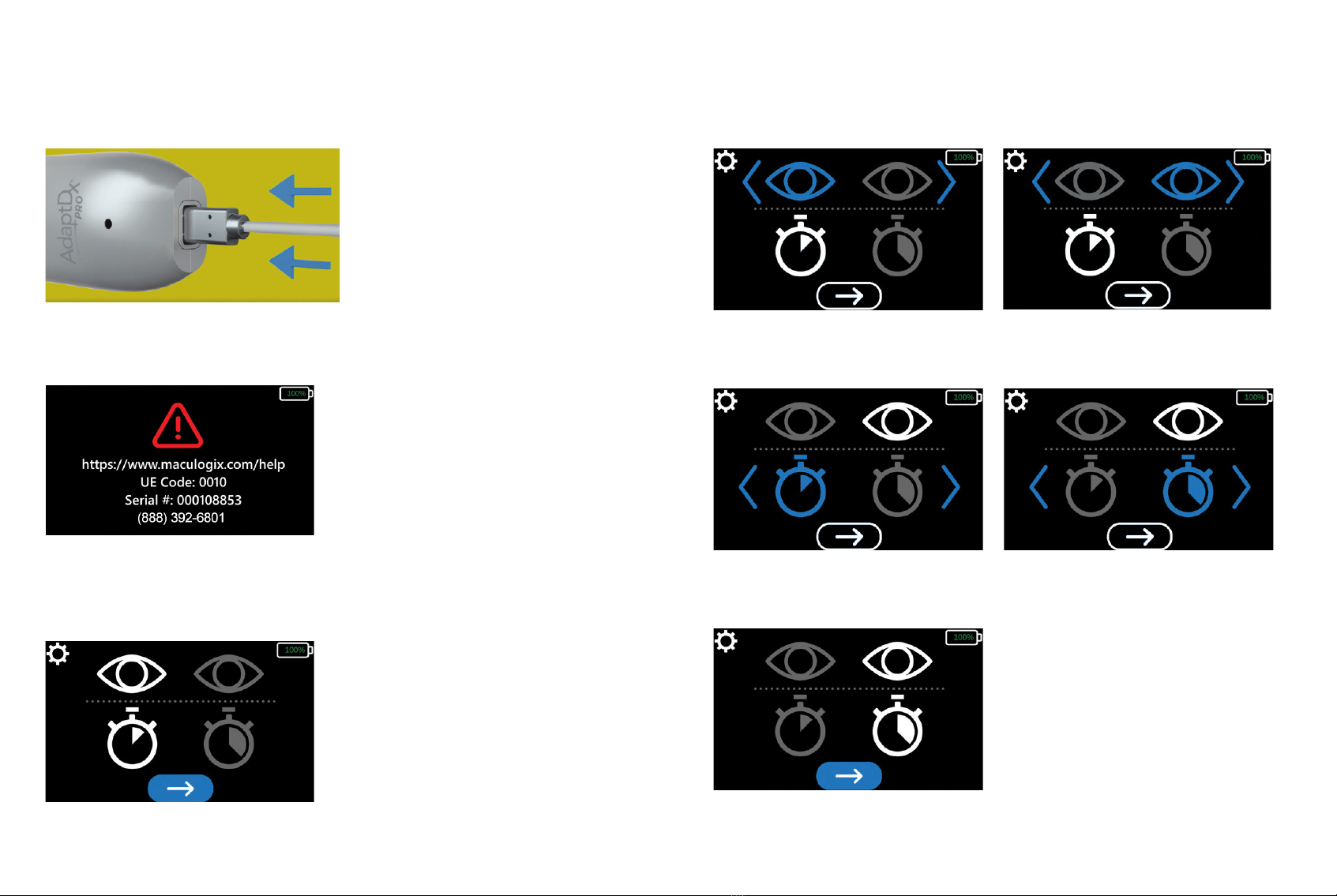
8. Troubleshooting
DESCRIPTION ACTIONS AND/OR SOLUTIONS
Unrecoverable Error (UE) Screen The user should call technical support using
the number on the screen and report UE
Code and Serial Number of the device to the
technical support representative for guidance.
The device will automatically power down
after 1 minute. To restart the device, press and
hold the power button until the power button
illuminates with a green light. The device will
return to the home screen.
Frozen Screen Power down the device by holding down
the power button until the green light on the
power button turns off. To restart the device,
press and hold the power button until the
power button illuminates with a green light.
Abort Test Press and hold the power button for 2
seconds. The device will abort the test and
return to the home screen.
9. Customer Support
For technical support or to order supplies and replacement parts, contact the device supplier. User
manuals are available for download in other languages at maculogix.com/manuals

20 21
10. Repair
MacuLogix provides return-to-factory service for the AdaptDx Pro. Contact MacuLogix at
1-888-392-6801, Monday through Friday between 9:00 AM and 5:00 PM US Eastern time if you
encounter any problems requiring maintenance.
The following components of the device can be replaced by the user.
Adjustable Head Strap – To replace the headstrap, disconnect the headstrap from the device
by depressing the buttons demonstrated in gure 10.1. To connect the new headstrap, align the
connections and press them into place as demonstrated in gure 10.2.
Figure 10.1
Figure 10.2
Figure 10.3
Figure 10.4
Padded Liner – To replace the padded liner, remove the padded liner from the velcro strips which
are fastened to the head strap. Align the new foam liner to the head strap and rmly press over the
velcro strips to ensure the foam liner is securely attached to the head strap. The proper alignment is
demonstrated in gure 10.3.
Eyecups – To replace the eyecups, remove each eyecup from the device by grasping and pulling the
outside corner of the rubber eyecup as demonstrated in gure 10.4. To connect the new eyecups, align
the eyecup tabs to the device notches and press them into place as demonstrated in gure 10.5.
USB-C Cable – To disconnect the USB cable from the device or the handheld controller, rmly grasp
the cable by the connector and disconnect it from the device. To connect the USB cable from the device
or the handheld controller, rmly grasp the cable by the connector and insert the cable connector into
the device connection port as demonstrated in gure 10.6 and 10.7.
Only MacuLogix supplied USB-C cables should be connected to the AdaptDx Pro device
and it’s components.
Figure 10.5
Figure 10.6 Figure 10.7

22 23
11. Disposal
The AdaptDx Pro includes electronics, display screens, batteries and other components that may release
toxic materials into the environment with improper disposal. Disposal of the AdaptDx Pro should be in
accordance with applicable state and local laws for the disposal of electronic equipment.
12. Specications
Photobleaching Subsystem
• Mechanism: ash
• Bleaching Wavelength: 505 nm
• Bleaching Intensity: 76% effective bleach
Stimulus Subsystem
• Stimulus Wavelength: 505 nm
• Stimulus Duration: 200 msec
• Stimulus Size: 2°-diameter
• Stimulus Location: 5° inferior to the xation light
• Maximum Stimulus Intensity: 20.9 scot mlx
• Dynamic Range of Stimulus: 4 log units
Fixation Subsystem
• Fixation Wavelength: 635 nm
• Fixation Intensity: 0.9 phot mlx
Operation
• Maximum Test Duration: Rapid Test is 6.5 minutes; Extended Test is 20 minutes
General
• Dimensions: 16.5 cm (height) x 22.3 cm (width) x 34.8cm (depth)
• Weight: 1.1 kg (AdaptDx Pro, AdaptDx Pro Controller and cable)
• AC Charger Specications: 100-240VAC, 50-60Hz, 0.6A

24 25
Environmental Requirements
• Operating Limits
-Temperature: 10° C to 35° C
-Humidity: 20% RH to 80% RH (non-condensing)
-Atmospheric Pressure: 700 hPa to 1,060hPa
• Transport and Storage Limits
-Temperature: -20° C to 65° C
-Humidity: 20% RH to 80% RH (non-condensing)
-Atmospheric Pressure: 500 hPa to 1,060 hPa
13. Electrical Safety and EMC
AdaptDx Pro IEC 60601-1 Classications
• AC Charger – Class II (type of protection against electrical shock)
• AdaptDx Pro – Class III (type of protection against electrical shock)
• Type B (degree of protection against electrical shock)
• Ordinary IP30 (degree of protection against solid particle and ingress of water)
• Not sterile
• Not suitable for use in the presence of a ammable anesthetics mixture with air or with oxygen or
with nitrous oxide
• Continuous mode of operation
Electrical Safety
The AdaptDx Pro and all its accessories are suitable for use in a patient environment. The AdaptDx Pro
Comfort Guards, foam liner, headstrap, and controller are applied parts that contact the patient.
WARNING: No modication of this equipment is allowed.
WARNING: Do not place any container holding liquid near the AdaptDx Pro.
Environmental Requirements
• Operating Limits
-Temperature: 10° C to 35° C
-Humidity: 20% RH to 80% RH (non-condensing)
-Atmospheric Pressure: 700 hPa to 1,060hPa
• Transport and Storage Limits
-Temperature: -20° C to 65° C
-Humidity: 20% RH to 80% RH (non-condensing)
-Atmospheric Pressure: 500 hPa to 1,060 hPa
13. Sécurité électrique et CEM
Classications CEI 60601-1 de l’AdaptDx Pro
• Chargeur CA – Classe II (type de protection contre les chocs électriques)
• AdaptDx Pro – Classe III (type de protection contre les chocs électriques)
• Type B (degré de protection contre les chocs électriques)
• IP30 ordinaire (degré de protection contre l’intrusion de particules solides et d’eau)
• Non stérile
• Ne convient pas à une utilisation en présence d’un mélange anesthésique inammable à l’air, à
l’oxygène ou à l’oxyde nitreux
• Fonctionnement en continu
Sécurité électrique
L’AdaptDx Pro et tous ses accessoires peuvent être utilisés dans un environnement de soins. Les
protections Comfort Guard, le rembourrage en mousse, la sangle et le contrôleur de l’AdaptDx Pro sont
des parties appliquées en contact avec le patient.
AVERTISSEMENT : la modication de cet appareil est interdite.
AVERTISSEMENT : ne pas placer de récipient contenant un liquide à proximité de
l’AdaptDx Pro.

26 27
AVERTISSEMENT : ne pas tenter de retirer les protections de l’AdaptDx Pro ou de
modier le système en aucune manière. Seul un technicien AdaptDx Pro agréé est autorisé à
effectuer les réparations ou apporter des modications au système. Le retrait des protections
ou la modication du système pourrait provoquer un choc électrique ou présenter d’autres
risques pour la sécurité.
Conseils concernant les câbles/la connectivité
Article Longueur maximale Commentaires
Chargeur de la batterie du contrôleur
de l’AdaptDx Pro à câble intégré
1,2 m Utiliser uniquement le câble
fourni par MacuLogix
Bouton de réponse du patient à câble
intégré
1,4 m Utiliser uniquement le câble
fourni par MacuLogix
AVERTISSEMENT : les appareils de communications RF portables (y compris les
périphériques, tels que les câbles d’antenne et les antennes externes) ne doivent pas être
utilisés à moins de 30 cm de toute pièce de l’AdaptDx Pro, y compris des câbles indiqués
par le fabricant. Une dégradation des performances de cet appareil pourrait sinon s’ensuivre.
Consulter la section ci-dessous concernant les distances de séparation recommandées.
AVERTISSEMENT : l’utilisation d’accessoires, de transducteurs ou de câbles autres que
ceux recommandés avec l’AdaptDx Pro peut entraîner une augmentation des émissions ou
une diminution de l’immunité de l’AdaptDx Pro.
Directives concernant les câbles/la connectivité
Respecter les directives suivantes concernant les câbles et la connectivité pour assurer la
conformité aux normes de compatibilité électromagnétique. Ne pas tenter de brancher des
câbles, hubs USB ou dispositifs autres que ceux recommandés sur l’AdaptDx Pro.
Compatibilité électromagnétique (CEM)
Des précautions particulières doivent être prises avec l’AdaptDx Pro quant à la CEM, et son installation et
sa mise en service doivent être effectuées conformément aux informations sur la CEM fournies dans ce
document.
WARNING: Do not attempt to remove any of the AdaptDx Pro covers or modify the
system in any way. Only an authorized AdaptDx Pro service technician should perform
repairs or make modications to the system. Removing covers or modifying the system
could result in electrical shock or other safety hazards.
Cable / Connectivity Guidance
Item Maximum Length Comments
AdaptDx Pro Controller
Battery Charger with
integrated cable
4 ft / 1.2 m Use only cable supplied by
MacuLogix
Patient Response button with
integrated cable
4.4 ft / 1.4 m Use only cable supplied by
MacuLogix
WARNING: Portable RF communications equipment (including peripherals such as
antenna cables and external antennas) should be used no closer than 30 cm (12 inches) to
any part of the AdaptDx Pro, including cables specied by the manufacturer. Otherwise,
degradation of the performance of this equipment could result. Please see section below
regarding recommended separation distances.
WARNING: The use of accessories, transducers, or cables with the AdaptDx Pro other
than those specied may result in increased emissions or decreased immunity of the
AdaptDx Pro.
Cables / Connectivity Guidelines
The following cable and connectivity guidelines must be followed to ensure compliance with the
electromagnetic compatibility. Do not attempt to connect cables, USB hubs or devices to the AdaptDx
Pro other than those listed.
Electromagnetic Compatibility (EMC)
The AdaptDx Pro needs special precautions regarding EMC and needs to be installed and put into service
according to the EMC information provided herein.

28 29
Guidance and manufacturer’s declaration – electromagnetic emissions
The AdaptDx Pro is intended for use in the electromagnetic environment specied below. The
customer or the user of the AdaptDx Pro should assure that it is used in such an environment.
Emissions test Compliance Electromagnetic environment – guidance
RF Emissions
CISPR 11
Group 1 The AdaptDx Pro uses RF energy only for its
internal function. Therefore, its RF emissions
are very low and are not likely to cause any
interference in nearby electronic equipment.
RF Emissions
CISPR 11
Class B The AdaptDx Pro is suitable for use in a typical
commercial or hospital environment connected
to the public low-voltage power supply
network.
Harmonic Emissions
IEC 61000-3-2
Class B
Voltage uctuations/ icker
emissions IEC 61000-3-3
Complies
AVERTISSEMENT : l’AdaptDx Pro ne doit pas être utilisé à proximité, ou posé sur ou
sous d’autres appareils. S’il est impossible de l’utiliser autrement, vérier que l’appareil ou le
système fonctionne normalement dans la conguration dans laquelle il sera utilisé
REMARQUE : l’AdaptDx Pro contient un module WiFi (ident. FCC : TFB 1004/IC : 5969A-1004) et
un module RFID (ident. FCC : QV5MERCURY6EN/IC : 5407A-MERCURY6EN) certiés. Ces modules
n’ont pas été testés dans le cadre de l’évaluation de la norme CEI 60601-1-2.
Le module WiFi est un émetteur de système de transmission numérique utilisant DSSS (DBPSK/DQPSK/
CCK) [802.11b]), OFDM (BPSK/QPSK/16QAM/64QAM/256QAM [802.11 a/g/n/ac]), à des fréquences
et une puissance aux États-Unis et au Canada de : 2412,0 - 2462,0 MHz à 0,14 W ERP 0,10747 W,
5180,0 - 5230,0 MHz à 0,038 W ERP 0,0582 W, 5260,0 5320,0 MHz à 0,024 W ERP 0,03676 W,
5500,0 - 5720,0 MHz à 0,082 W ERP 0,12559 W et 5745,0 - 5825,0 MHz à 0,038 W ERP 0,0582 W.
Le module RFID est un émetteur à spectre étalé utilisant la modulation PR-ASK (modulation d’amplitude
par inversion de phase), à des fréquences et une puissance aux États-Unis et au Canada de : 917,4 -
927,2 MHz à 0,512 W ERP 0,48353 W et 917,5 - 922,5 MHz à 0,454988 W ERP 0,42969 W.
Directives et déclaration du fabricant – Émissions électromagnétiques
L’AdaptDx Pro est destiné à être utilisé dans l’environnement électromagnétique spécié ci-dessous.
Le client ou l’utilisateur de l’AdaptDx Pro doit s’assurer de l’utiliser dans ces mêmes conditions.
Test d’émissions Conformité Environnement électromagnétique – Directives
Émissions RF
CISPR 11
Groupe 1 L’AdaptDx Pro utilise de l’énergie RF pour
son fonctionnement interne uniquement. Ses
émissions RF sont donc très faibles et ne risquent
pas de provoquer d’interférences avec les
équipements électroniques présents à proximité.
Émissions RF
CISPR 11
Classe B L’AdaptDx Pro convient à une utilisation dans
des établissements commerciaux ou hospitaliers
classiques reliés au réseau d’alimentation public
basse tension.
Émissions d’harmoniques
CEI 61000-3-2
Classe B
Variations de tension/émissions
de papillotement CEI 61000-3-3
Conforme
WARNING: The AdaptDx Pro should not be used adjacent to or stacked with other
equipment. If adjacent or stacked use is necessary, the equipment or system should be
observed to verify normal operation in the conguration in which it will be used.
NOTE: The AdaptDx Pro contains a certied WiFi module (FCCID: TFB-1004 / IC: 5969A-1004) and
RFID module (FCCID: QV5MERCURY6EN / IC: 5407A-MERCURY6EN). These modules were not
tested as part of the IEC 60601-1-2 evaluation.
The WiFi module is a digital transmission system transmitter utilizing DSSS (DBPSK / DQPSK / CCK)
[802.11b]), OFDM (BPSK / QPSK / 16QAM / 64QAM / 256QAM [802.11 a/g/n/ac]), with frequencies
and power for the USA and Canada of: 2412.0-2462.0 MHz @ 0.14 W ERP 0.10747 W, 5180.0-
5230.0 MHz @ 0.038 W ERP 0.0582 W, 5260.0-5320.0 MHz @ 0.024 W ERP 0.03676 W, 5500.0-
5720.0 MHz @ 0.082 W ERP 0.12559 W, and 5745.0-5825.0 MHz @ 0.038 W ERP 0.0582 W. The
RFID module is a spread spectrum transmitter utilizing PR-ASK (Phase Reversal - Amplitude Shift Keying),
with frequencies and power for USA and Canada of: 917.4-927.2 MHz @ 0.512 W ERP 0.48353 W and
917.5-922.5 MHz @ 0.454988 W ERP 0.42969 W.

30 31
Guidance and manufacturer’s declaration – electromagnetic immunity
The AdaptDx Pro is intended for use in the electromagnetic environment specied below. The
customer or the user of the AdaptDx Pro should assure that it is used in such an environment.
Immunity test IEC 60601
test level
Compliance level Electromagnetic
environment –
guidance
Electrostatic discharge
(ESD)
IEC 61000-4-2
±8 kV contact
±15 kV air
±8 kV contact
±15 kV air
Floors should be wood,
concrete or ceramic tile.
If oors are covered with
synthetic material, the
relative humidity should
be at least 30%.
Electrical fast transient/
burst
IEC 61000-4-4
±2 kV for power supply
lines
±1 kV for input/output lines
±2 kV for power supply
lines
±1 kV for input/output
lines
Mains power quality
should be that of a typical
commercial or hospital
environment.
Surge
IEC 61000-4-5
±1 kV differential mode
±2 kV common mode
±1 kV differential mode
±2 kV common mode
Mains power quality
should be that of a typical
commercial or hospital
environment.
Voltage dips, short
interruptions and voltage
variations on power
supply input lines
IEC 61000-4-11
<5% UT
(>95% dip in UT)
for 0,5 cycle at 0°, 45°, 90°,
135°, 180°, 225°, 270° and
315°.
70% UT
(30% dip in UT)
for 0.5 sec.
<5% UT
(>95% dip in UT)
for 5 sec.
<5% UT
(>95% dip in UT)
for 0,5 cycle at 0°, 45°,
90°, 135°, 180°, 225°,
270° and 315°.
70% UT
(30% dip in UT)
for 0.5 sec.
<5% UT
(>95% dip in UT)
for 5 sec.
Mains power quality
should be that of a
typical commercial or
hospital environment. If
the user of the AdaptDx
Pro charger requires
continued operation
during power mains
interruptions, it is
recommended that the
AdaptDx Pro be powered
from an uninterruptible
power supply.
Power frequency (50/60
Hz) magnetic eld
IEC 61000-4-8
30 A/m 30 A/m Power frequency
magnetic elds should be
at levels characteristic of a
typical location in a typical
commercial or hospital
environment.
NOTE: UT is the a.c. mains voltage prior to application of the test level.
Directives et déclaration du fabricant – Immunité électromagnétique
L’AdaptDx Pro est destiné à être utilisé dans l’environnement électromagnétique spécié ci-dessous.
Le client ou l’utilisateur de l’AdaptDx Pro doit s’assurer de l’utiliser dans ces mêmes conditions.
Test d’immunité CEI 60601 Niveau
de test
Niveau de
conformité
Environnement
électromagnétique – Directives
Décharge
électrostatique (DES)
CEI 61000-4-2
±8 kV au contact
±15 kV dans l’air
±8 kV au contact
±15 kV dans l’air
Floors should be wood, concrete
or ceramic tile. If oors are covered
with synthetic material, the relative
humidity should be at least 30%.
Salves/transitoires
électriques rapides
CEI 61000-4-4
± 2 kV pour les
lignes d’alimentation
électrique
± 1 kV pour les lignes
d’entrée/de sortie
± 2 kV pour les
lignes d’alimentation
électrique
± 1 kV pour les lignes
d’entrée/de sortie
La qualité de l’alimentation secteur
doit correspondre à celle d’un
environnement commercial ou
hospitalier type.
Surtension
CEI 61000-4-5
± 1 kV mode
différentiel
± 2 kV mode commun
± 1 kV mode
différentiel
± 2 kV mode commun
La qualité de l’alimentation secteur
doit correspondre à celle d’un
environnement commercial ou
hospitalier type.
Chutes de tension,
courtes interruptions et
variations de la tension
sur les lignes d’entrée
CEI 61000-4-11
< 5 % UT
(> 95 % de baisse
d’UT)
pour 0,5 cycle à 0°,
45°, 90°,
135°, 180°, 225°,
270° et
315°.
70 % UT
(30 % de baisse d’UT)
pour 0,5 s
< 5 % UT
(> 95 % de baisse
d’UT) pour 5 s.
< 5 % UT
(> 95 % de baisse
d’UT)
pour 0,5 cycle à 0°,
45°,
90°, 135°, 180°, 225°,
270° et 315°.
70 % UT
(30 % de baisse d’UT)
pour 0,5 s
< 5 % UT
(> 95 % de baisse
d’UT) pour 5 s.
La qualité de l’alimentation secteur
doit correspondre à celle d’un
environnement commercial ou
hospitalier type. Si l’utilisateur
de l’AdaptDx Pro nécessite une
utilisation continue même en cas de
coupure du courant secteur, il est
recommandé d’utiliser un onduleur
pour alimenter l’AdaptDx Pro
Champ magnétique à
la fréquence du réseau
(50/60 Hz)
CEI 61000-4-8
30 A/m 30 A/m Les champs magnétiques à la
fréquence du réseau doivent être
à des niveaux caractéristiques d’un
emplacement type d’environnement
commercial ou hospitalier standard.
REMARQUE : UT est la tension secteur c.a. avant application du niveau de test.

32 33
Recommended separation distances between portable and mobile RF
communication equipment and the AdaptDx Pro
The AdaptDx Pro is intended for use in an electromagnetic environment in which radiated RF
disturbances are controlled. The customer or the user of the AdaptDx Pro can help prevent
electromagnetic interference by maintaining a minimum distance between portable and mobile
RF communications equipment (transmitters) and the AdaptDx Pro as recommended below,
according to the maximum output power of the communications equipment.
Rated maximum
output power of
transmitter
W
Separation distance according to frequency of transmitter
m
150 kHz to 80 MHz
dd=1.17√PP
150 kHz to 80 MHz
dd=1.17√PP
150 kHz to 80 MHz
dd=2.33√PP
0,01 0.12 0.12 0.23
0,1 0.37 0.37 0.74
11.17 1.17 2.33
10 3.70 3.70 7.37
100 11.70 11.70 23.30
For transmitters rated at a maximum output power not listed above, the recommended
separation distance d in meters (m) can be estimated using the equation applicable to the
frequency of the transmitter, where P is the maximum output power rating of the transmitter in
watts (W) according to the transmitter manufacturer.
NOTE: 1 At 80 MHz and 800 MHz, the separation distance for the higher frequency range
applies.
NOTE: 2 These guidelines may not apply in all situations. Electromagnetic propagation is affected
by absorption and reection of structures, objects and people.
Distances de séparation recommandées entre les équipements de
communication RF portables et mobiles et l’AdaptDx Pro
L’AdaptDx Pro est conçu pour être utilisé dans un environnement électromagnétique où les
perturbations de RF rayonnée sont contrôlées. Le client ou l’utilisateur de l’AdaptDx Pro peut
faciliter la prévention des interférences électromagnétiques en maintenant une distance minimale
entre les équipements de communication RF portables et mobiles (émetteurs) et l’AdaptDx Pro,
comme recommandé ci-dessous, selon la puissance de sortie maximale de l’équipement de
communication.
Puissance de
sortie nominale
maximale de
l’émetteur
W
Distance de séparation selon la fréquence de l’émetteur
m
150 kHz à 80 MHz
dd=1,17√PP
150 kHz à 80 MHz
dd=1,17√PP
150 kHz à 80 MHz
dd=2,33√PP
0,01 0,12 0,12 0,23
0,1 0,37 0,37 0,74
11,17 1,17 2,33
10 3,70 3,70 7,37
100 11,70 11,70 23,30
Pour les émetteurs dont la puissance de sortie nominale maximale n’est pas répertoriée ci-dessus,
la distance de séparation recommandée d en mètres (m) peut être estimée à l’aide de l’équation
applicable à la fréquence de l’émetteur, où P correspond à la puissance de sortie nominale
maximale de l’émetteur en watts (W) selon le fabricant de l’émetteur.
REMARQUE 1 : à 80 MHz et 800 MHz, la distance de séparation pour la plage de fréquence la
plus élevée s’applique.
REMARQUE 2 : ces recommandations peuvent ne pas s’appliquer à toutes les situations. La
propagation électromagnétique est affectée par l’absorption et la réexion des structures, des
objets et des personnes.

34 35
14. Identication des symboles
1. Fabricant
2. Numéro de modèle
3. Numéro de série
4. Mode d’emploi
5. Rep. autorisé dans la CE
6. Dispositif médical
7. Marquage CE
8. Date de fabrication
REF
SN
EC REP
MD
9. Marquages électriques
-Courant continu
-Partie appliquée
10. Déchet d’équipements
électrique et électronique
11. Marquage ETL
12. Fragile
13. Maintenir au sec
14. Limite de température
MacuLogix, Inc.
1000 Kreider St, Ste 700
Middletown, PA 17057
Phone +1.888.392.6801
www.maculogix.com
Medspace Medical Devices BV
Il Fiore Building B, 3rd Floor
Avenue Ceramique 227
6221 KX Maastricht
The Netherlands
Australian Sponsor:
Optos Australia
10 Meyer Court
Beverley
South Australia, 5009
EC REP
15. Limite d’humidité
16. Limite de pression atmos
17. Étiquette d’avertissement
de batterie au lithium
18. Symbole Ne pas réutiliser
19. Bouton marche/arrêt
20. Rayonnement
électromagnétique non
ionisant
65 C
-20 C
1 888 392 6801
14. Symbol ID
1. Manufacturer
2. Model Number
3. Serial Number
4. IFU
5. EC Authorized Rep
6. Medical Device
7. CE mark
8. Date of Manufacture
REF
SN
EC REP
MD
9. Electrical markings
-DC Power
-Applied Part
10. Waste Electrical and
Electronic Equipment
11. ETL Listing
12. Fragile
13. Keep Dry
14. Temp Limit
MacuLogix, Inc.
1000 Kreider St, Ste 700
Middletown, PA 17057
Phone +1.888.392.6801
www.maculogix.com
Medspace Medical Devices BV
Il Fiore Building B, 3rd Floor
Avenue Ceramique 227
6221 KX Maastricht
The Netherlands
Australian Sponsor:
Optos Australia
10 Meyer Court
Beverley
South Australia, 5009
EC REP
15. Humidity Limit
16. Atmos Pressure Limit
17. Lithium Battery
Warning Label
18. Do Not Re-Use Symbol
19. Power Button
20. Non-ionizing
Electromagnetic Radiation
65 C
-20 C
1 888 392 6801
Table of contents
Popular Medical Equipment manuals by other brands

BLADDERSCAN
BLADDERSCAN BVI 9400 Operation & maintenance manual

bort medical
bort medical OmoXpress light quick guide

Genadyne
Genadyne UNO+ user manual

Aesculap
Aesculap GA346 Instructions for use/Technical description

Sirona
Sirona orthophos xg 3 installation instructions

Bioness
Bioness BITS Supplemental guide