Macurco AimSafety PM150-CO2 User manual

AimSafety™ PM150-CO2
Carbon Dioxide Gas Monitor
User Instructions

PM150-CO2 Portable Gas Monitor
REV – 1.0 [34-2900-0211-5] 2 |Page
1 General Information ....................................................................................................................................................... 4
2 Specifications .................................................................................................................................................................. 4
2.1 PM150-CO2 Specifications...................................................................................................................................... 4
2.2 Sensor Specification ................................................................................................................................................ 4
3 Product Overview............................................................................................................................................................ 5
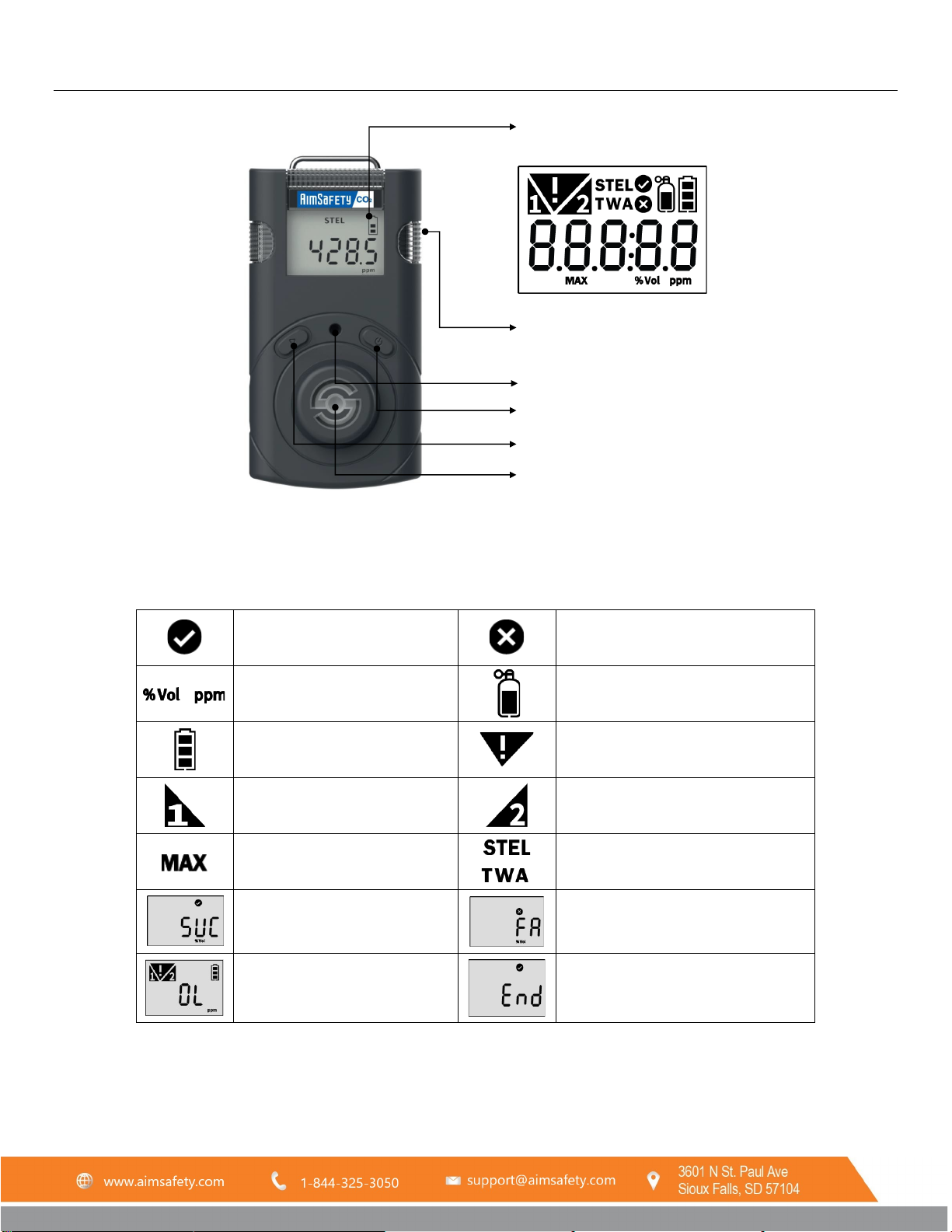
3.1 Monitor Overview................................................................................................................................................... 5
3.2 Display Overview..................................................................................................................................................... 5
4 Activation ........................................................................................................................................................................ 6
4.1 Activating the PM150-CO2...................................................................................................................................... 6
4.2 Error Messages........................................................................................................................................................ 6
4.3 Bump Test ............................................................................................................................................................... 7
5 Mode............................................................................................................................................................................... 8
5.1 Measuring Mode..................................................................................................................................................... 8
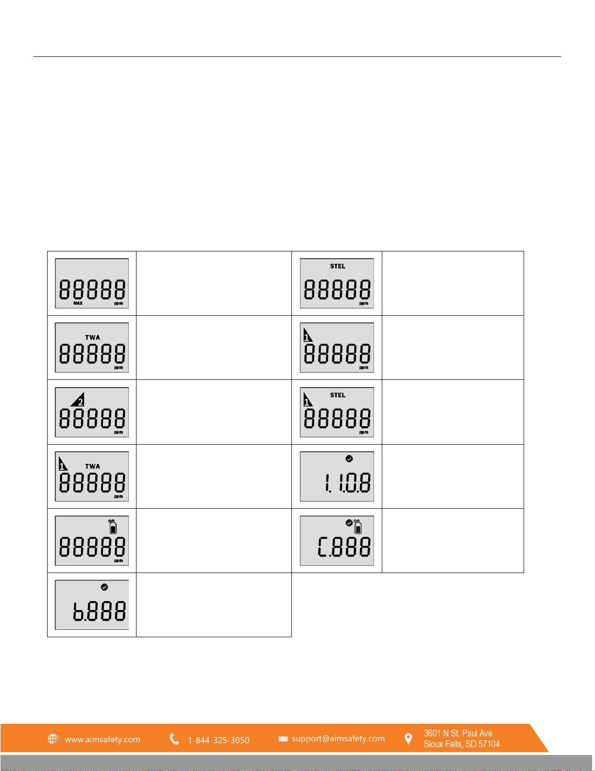
5.2 Display Mode .......................................................................................................................................................... 8
5.3 Settings Mode ......................................................................................................................................................... 9
5.4 Setting Mode Symbols............................................................................................................................................. 9
6 Setting Mode................................................................................................................................................................. 10
6.1 Alarm Activation.................................................................................................................................................... 10
6.2 Adjust alarm set points ......................................................................................................................................... 10
6.3 Data Log ................................................................................................................................................................ 10
7 Menu Screens................................................................................................................................................................ 11
7.1 Menu Flow Chart................................................................................................................................................... 11
7.2 Clear Max (Peak Values)........................................................................................................................................ 12
7.3 Clear STEL and TWA............................................................................................................................................... 12
7.4 Adjust Unit ............................................................................................................................................................ 12
7.5 Factory Reset......................................................................................................................................................... 12
7.6 Self-Test................................................................................................................................................................. 13
8 Calibration..................................................................................................................................................................... 14
8.1 Calibration Gas Values .......................................................................................................................................... 14
8.2 Zero (N2) Calibration............................................................................................................................................. 14
8.3 Span Calibration .................................................................................................................................................... 15
9 Software Manager ........................................................................................................................................................ 16
9.1 Software Overview................................................................................................................................................ 16
9.1.1 Read .............................................................................................................................................................. 17
9.1.2 Write ............................................................................................................................................................. 17
9.1.3 Calibration..................................................................................................................................................... 17
9.1.4 Log................................................................................................................................................................. 17
9.1.5 Firmware Upgrade ........................................................................................................................................ 17
9.2 Window menu....................................................................................................................................................... 18
9.2.1 Menu – File.................................................................................................................................................... 18
9.2.2 Menu – Tools................................................................................................................................................. 18
9.2.3 Menu – Device............................................................................................................................................... 18
10 Maintenance ............................................................................................................................................................. 19
10.1 Sensor Replacement ............................................................................................................................................. 20
10.2 Battery Replacement ............................................................................................................................................ 20
11 Battery Charging ....................................................................................................................................................... 21
11.1 To charge the battery:........................................................................................................................................... 21

PM150-CO2 Portable Gas Monitor
REV – 1.0 [34-2900-0211-5] 3 |Page
12 Appendix A – Table of Figures................................................................................................................................... 21
Product Limited Warranty ................................................................................................................................................... 22
Technical Support Contact Information ............................................................................................................................ 22
General Contact Information ............................................................................................................................................ 22
WARNING
Any unauthorized attempt to repair or modify the product, or any other cause of damage beyond the range
of the intended use, including damage by fire, lightening, or other hazard, voids liability of the manufacturer.
Only activate this product only if sensor, visual, detection, and audible cover are clear from contaminants such
as dirt and debris that could block the area where gas is to be detected.
Do not clean and rub the LCD screen of the products with a dry cloth or hands in hazardous environment to
prevent static electricity buildup.
If the CO2 concentration reaches 0 ppm, a calibration should be performed.
CAUTIONS
Before operating this device, please read and understand this manual.
This device is not an analyzer, but a gas detector.
Do not use the device if calibration and self-test continuously fail.
Clean device with a soft cloth. Do not use chemical substances for cleaning.
View a serial number on the label at the back side of the device. (ex. 2021.01.01)
1. The serial number indicates below.
ex: SL 01 01 001 2021(Year) 01(Months) 01(Day) 001(Manufacture Order)

PM150-CO2 Portable Gas Monitor
REV – 1.0 [34-2900-0211-5] 4 |Page
1General Information
The PM150-CO₂ is a portable single gas detector designed to detect the presence of carbon dioxide gas in ambient
environment. When activated, PM150-CO₂ continuously monitors ambient air for the presence of carbon dioxide gas
and alerts the user to potentially unsafe exposure with LED, vibrating, and audible alarms if gas concentration exceeds
alarm set points. The settings value can be adjusted manually or by connecting to the PC software.
2Specifications
2.1 PM150-CO2 Specifications
Model
PM150-CO2
Detector
Sensor Type
Nondispersive infrared (NDIR)
Measurement
Diffusion type
Display
LCD display
Audible
90dB at 10cm
Warning Lamp
Red Flashing LEDs
Vibration
Vibration Alarm
Battery
Rechargeable Li-ion (polymer) power supply unit (500mAh)
Charging Time 100 minutes from empty battery to fully charge based on power off
state and charging with adaptor
Temperature
-20ºC to +50ºC
Humidity
5% to 95% RH (Non-condensing)
Case
Rubber Enclosure
Accessories
Calibration Cap, Charging Cable (USB C-Type) and Adaptor
Calibration Flow Rate
Flow rate: 0.2 LPM (N
2
, CO
2
)
Size
2.13” (W) x 3.92” (H) x 1.53” (D) (54 mm x 99.5 mm x 38.8 mm)
Weight
4.76 oz (135 g)
Operating Life
14 days (Expected) (in measuring mode without alarm)
Event Log
Recent 30 alarms
Approval
EMC Directive (2014/30/EU), ROHS
2.2 Sensor Specification
Gas Measuring range Low Alarm High Alarm Resolution
CO20-5.0% vol
0-50,000 ppm
0.5% vol
5,000 ppm
1% vol
10,000 ppm
0.01% vol
100 ppm

PM150-CO2 Portable Gas Monitor
REV – 1.0 [34-2900-0211-5] 5 |Page
3Product Overview
3.1 Monitor Overview
Figure 3-1
3.2 Display Overview
Calibration / Setting Success
Calibration / Setting Failure
Measurement Unit
Standard Gas Calibration
Remaining Battery
Alarm Condition
1st Alarm Display
2nd Alarm Display
Max Value
Short Term Exposure Limit
Time Weighted Average
Test Success
Test Fail
Over Limit
End of Test
LCD display
Alarm LED
Buzzer
Power
Button
Function Key
Gas
sensor

PM150-CO2 Portable Gas Monitor
REV – 1.0 [34-2900-0211-5] 6 |Page
4Activation
4.1 Activating the PM150-CO2
Move the monitor to a fresh air environment, which is free of hazardous gas. Press and hold down the power button for
approximately two (2) seconds until the gas type (CO2) is displayed. Upon activation, gas type (CO2), firmware version, and
display appears, and thedetector performs the self-diagnostic test for 10 seconds. After self-test is successful, the detector
countdown is displayed for 10 seconds. Allow the detector to stabilize for 90 seconds until warm up message (---) is no
longerdisplayed. The detector will then display the current CO2concentration.
4.2 Error Messages
If stabilization has failed, Error mark is displayed and measuring mode will not be entered. In this case,contact
AimSafety for repair or return.
Err-1 Initial setting error
Err-2 Sensor error
Err-3 Memory error
L-bat
Low battery

PM150-CO2 Portable Gas Monitor
REV – 1.0 [34-2900-0211-5] 7 |Page
4.3 Bump Test
A bump test is used to test that the monitor is working properly. During a bump test, a known concentration of gas is
applied to the sensor to verify that the sensor responds to the gas, and the alarms activate. This is the only way to
effectively confirm that all characteristics of the monitor and the sensor are working correctly.
WARNING
A bump test should be conducted before each day’s use.
Ensure that you are in a clean environment before performing a Bump Test.
The monitor must be calibrated if it fails a Bump Test.
To perform the bump test:
•Prepare a gas cylinder with a CO2 concentration that exceeds the low and high alarm set points.
•Press and hold the Function key and power button for three seconds in the measurementmode. Press the Function
key until “TEST” is displayed and press the power button two (2) seconds to enter the mode.
•Press the Function key until “BTS is displayed and press the power button to activate it.
•After pressing the power button, apply a CO2gas over low and first alarm and the 30 seconds count down is
displayed.
•Once the test has passed, “SUC” (V) icon appears on the display. If test is failed, “FA” (X) mark appears on the display.

PM150-CO2 Portable Gas Monitor
REV – 1.0 [34-2900-0211-5] 8 |Page
5Mode
5.1 Measuring Mode
When activated, gas concentration is displayed in measuring mode
5.2 Display Mode
In the measuring mode, by pressing Function key, the following icons will appear in the following order.
Max value →STEL value →TWA value →1st alarm set point →2nd alarm set point →STEL alarm set point →
TWA alarm set point →Firmware version →Calibration concentration →Calibration interval remaining date →
Bump test interval remaining date.
• To move to the next menu, press the Function key.
• At the last step, press Function key or do not push any button for 10 seconds, the device will return to the
Measuring Mode.
Max Value
Measured STEL value
Measured TWA value
Low Alarm Value Setting
High Alarm Value Setting
STEL Alarm Value Setting
TWAAlarm Value Setting
Firmware version
Calibration Concentration
Calibration interval remaining
date
Bump test interval remaining date

PM150-CO2 Portable Gas Monitor
REV – 1.0 [34-2900-0211-5] 9 |Page
5.3 Settings Mode
In the settings mode, users can adjust set points, perform calibration, and reset previous values.
•To enter the setting mode, press and hold the Function key & power button simultaneously for three
seconds. The following menu ALr →CAL → CLr MAX → CLr and STEL, TWA →UnIt →InIt →tESt is
displayed.
•To move to the next menu, press the Function key.
•To enter the menu, press and hold down the power button.
5.4 Setting Mode Symbols
Setting
Submenu
LCD
Action
ALr 1st Alarm
2nd Alarm
1st Alarm concentration setting
2nd Alarm concentration setting
CAL
ZERO (N2) SPAN
(CO2)
Zero (N2) calibration Span (CO2)
calibration
CLr MAX
-
Delete maximum alarmConcentration
CLr STEL,
TWA
-
Delete STEL and TWAConcentration
Unit
%vol / ppm
Concentration unit conversion
Init
-
Reset
Test
Self
Bts
Self-test
Bump test

PM150-CO2 Portable Gas Monitor
REV – 1.0 [34-2900-0211-5] 10 |Page
6Setting Mode
6.1 Alarm Activation
When the gas concentration exceeds alarm set points, or
will be displayed and the device will vibrate,
flash (LED), and beep. To remove alarms, move to a clean air location. When a gas concentration is decreased
below the alarm set points, alarm will stop.
Low Alarm
•
Audible Alarm: Three (3) beeps per seconds
•
LED: Three (3) flashes per seconds
•
Vibration: One (1) vibration per second
High Alarm
•
Audible Alarm: Four (4) beeps per seconds
•
LED: Four (4) flashes per seconds
•
Vibration: One (1) vibration per second
STEL & TWA Alarm
•
Audible Alarm: Four (4) beeps per seconds
•
LED: Four (4) flashes per seconds
•
Vibration: One (1) vibration per second
6.2 Adjust alarm set points
• To enter the setting mode, press and hold the Function key and power button simultaneously
for two seconds.
• In the alarm setting icon, press and hold down the power button for two (2) seconds.
- Press the Function key to change the alarm set points.
- Press the power button to save the value and move to
the next step.
CAUTION
Ensure that the high alarm setpoint must be greater than low alarm setpoint. Alarm setpoints may vary by
a country, states, and company policy. Unless specified in your company’s safety instruction, use the preset
alarm setpoints. Before the alarm adjustment, check with your safety manager or authorized dealer.
Ensure Standard Factory alarm set points vary depending on countries, states, and companies.
Before changing alarm setpoints, ensure the alarm set points follow your local guidelines.
For safety, users are not allowed to set the 1st alarm value to zero. When attempting to set 1st alarm to zero,
the value will change to 400 ppm.
6.3 Data Log
The detector stores the last 30 event logs. If the data is filled, the new log event overwrites the oldest log events.
The data log is stored at one (1) minute intervals, and it stores about 64,000 data logs.
Data logs consisting of event log, bump, and calibrations are stored at one (1) minute intervals.
To transfer event logs and data log to a computer:
•Install the current AimSafety CO2USB link software found at www.macurco.com/downloads
•Connect the detector to a computer via the supplied USB-C cable.

PM150-CO2 Portable Gas Monitor
REV – 1.0 [34-2900-0211-5] 11 |Page
7Menu Screens
7.1 Menu Flow Chart
Figure 7-1

PM150-CO2 Portable Gas Monitor
REV – 1.0 [34-2900-0211-5] 12 |Page
7.2 Clear Max (Peak Values)
To delete the measured peak concentration in the detector, follow below steps.
1. Press the Function key & power button simultaneously and the Function key until CLr (max) is displayed.
2. Press the power button to clear the peak value.
3. After the successful activation, SUC (V) mark is displayed. If it fails, FA (X) mark is
displayed.
7.3 Clear STEL and TWA
To delete the measured STEL and TWA value in the detector, follow below steps:
1. Press the Function key until CLr (STEL & TWA) is displayed.
2. Press the power button to delete the TWA and STEL values
3. After the successful activation, SUC with (V) mark is displayed.
7.4 Adjust Unit
To change the unit (ppm or %Vol) in the detector, follow below steps:
1. Press the Function key until UnIt is displayed and power button to enter the mode.
2. Press the Function key to select a unit (ppm or %Vol) and power button to save it.
3. After the successful activation, SUC (V) mark is displayed. If it fails, FA (X) mark is displayed.
7.5 Factory Reset
To restore the factory setting, please follow below steps:
1. Press the Function key until “InIt” is displayed.
2. Press the power button to apply it.
3. After the successful activation, SUC (V) mark is
displayed. If it fails, FA (X) mark is displayed.

PM150-CO2 Portable Gas Monitor
REV – 1.0 [34-2900-0211-5] 13 |Page
7.6 Self-Test
To perform the self-diagnostic test, follow below steps.
1. Press the Function key until Test is displayed
2. Press the power button for three seconds. In the “SELF” display, press the power button for three
seconds to activate the self-test. While it is activated, the detector will test LED, beeping, vibration, flash
memory, and sensor. After the successful test, (V) mark is displayed. If the test fails, FA with (X) mark is
displayed.
3. If the self-test fails, the Error message appears.

PM150-CO2 Portable Gas Monitor
REV – 1.0 [34-2900-0211-5] 14 |Page
8Calibration
CAUTION
Initial calibration is performed on all devices prior to shipment.
The detector has the zero calibration (N2) and span calibration (CO2)
The frequency of calibration depends on the use case. More frequent calibrations may be required
depending on the frequency of use and personal risk. For instance, if you use the device daily, weekly or
monthly calibration may need to be performed, while the device is used a few times a year, monthly or
quarterly calibration may be required. Before calibration, check with your safety managers to ensure
calibration accessibility.
If calibration fails, attempt to perform a re-calibration. If the calibration continues to fail, contact an
authorized distributor or AimSafety.
8.1 Calibration Gas Values
Gas Type Zero (N₂) Span (CO₂)
Concentration 99.99% Vol 20,000 ppm, 2% Vol
8.2 Zero (N2) Calibration
1. Assemble the calibration equipment with zero gas cylinder. See
Figure 8-1
2. In the “CAL” mode, press the Function key to move to the “ZErO”
calibration.
3. Attach the calibration cap to the detector.
4. Press and hold the power button for three (3) seconds to start the zero
calibration. Once the countdown timer has started, open the valve on the
regulator to start the flow of gas.
5. After 90 seconds, when the zero calibration is successful, success
message (V) appears. If the zero calibration fails, FAIL message (X)
appears.
Note: Press the power button during the 90 second countdown to abort the zero calibration.
CAUTION
Use the regulator with a flow rate of 0.2 LPM (Liters per minute).
Figure 8-1

PM150-CO2 Portable Gas Monitor
REV – 1.0 [34-2900-0211-5] 15 |Page
8.3 Span Calibration
1. Assemble the calibration equipment with span gas cylinder. See Figure 8-1
2. In the “CAL” mode, press the Function key to move to the “SPAn” calibration.
3. Attach the calibration cap to the detector.
4. Press and hold the power button for three (3) seconds to start the span calibration. Once the countdown timer
has started, open the valve on the regulator to start the flow of gas.
5. After 90 seconds, when the span calibration is successful, success message (V) appears.
If span calibration fails, fail message (X) appears.
Note: Press the power button during the 90 second countdown to abort the span calibration.
CAUTION
Do not change the calibration concentration without a safety managers authorization.
Use the regulator with a flow rate of 0.2 LPM (Liters per minute).

PM150-CO2 Portable Gas Monitor
REV – 1.0 [34-2900-0211-5] 16 |Page
9Software Manager
9.1 Software Overview
Figure 9-1
• Sensor Type – The current sensor type in the device (CO₂, cannot be changed)
• Serial Number – PM150-CO2serial number
• Firmware Version – Current firmware version of the unit (can change by upgrading)
• User ID/Message – The User ID can be used to add a custom message
• Unit – Adjust measuring unit to ppm or %Vol
• Stealth – Disable the alarm, buzzer, and LED
• Calibration Use – Disable/Enable the calibration access
• Low Alarm & High Alarm – The 1st and 2nd alarm set points (Min/Max: 400 ppm (0.04% Vol)) - 49,999
capitalize (5% Vol)
• STEL Alarm & TWA Alarm – Short Term Exposure Limit and Time Weighted Average level of
concentration of CO₂ (Min/Max: 400 ppm (0.04% Vol) - 49,999 ppm (5% Vol)
• Gas Concentration – This allows a user to enter/amend correct concentration of the gas cylinder
(Min/Max: 400 ppm (0.04% Vol) - 49,999 ppm (5% Vol)
• Calibration Interval (day) – The calibration reminder can be adjusted from 0 (N/A) – 365 days (Default
setting is N/A)
• Bump Interval (Days) – The Bump test reminder can be adjusted from 0 (N/A) – 365 days (Default setting
is N/A)
• Self-Interval (Days) – The Self-test reminder can be adjusted from 0 (N/A) – 365 days (Default setting is
N/A)
Note:
- When the software is opened, the fields are grayed out and before it can be used, the “OPEN” button must
be clicked.
- Without clicking the “Write” button, configured and customized settings will not be applied, andneither be
saved.
- If the USB connection is successful, the “Success” icon appears. If the connection fails, reconnect
the USB cable or check the device manager to see the connection status.
Read
Write
Calibration
Log
Firmware

PM150-CO2 Portable Gas Monitor
REV – 1.0 [34-2900-0211-5] 17 |Page
9.1.1 Read
The “Read” button (upper-left side first icon) allows a user to retrieve the stored data.
9.1.2 Write
The “Write” button (upper-left side second icon) has one of the most important roles in this software interface.
All configurations and customized settings will be saved by clicking “Write” button. When a user configures the
instrument`s settings, “Write” button must be clicked and a message will pop-up. Click “Yes”.
9.1.3 Calibration
To perform the calibration using the software:
1. Connect the unit to the PC using instrument’s USB-C cable.
2. Attach the calibration cap and connect with zero (N2) or CO2
gas cylinder.
3. Open the software and click “Calibration” (middle-left side icon)
to open the calibration wizard.
4. Choose the calibration gas type and click “Start” and turn on
the cylinder valve.
5. The zero (N2) and span (CO2) calibrations each take 90
seconds.
9.1.4 Log
The most recent 30 logs will be stored in the device are
automatically erased one by one the earliest logs when new
events occur. There are two types of logs, “Event Log” and “Event
+ Data log”, available to download. Choose the log and click
“Download” button. The log files will be downloaded named with
the unit`s Serial number in a “.csv” format. Clicking the “Erase”
button will remove all the logs from the device’s memory and
cannot be recovered.
9.1.5 Firmware Upgrade
To upgrade the latest firmware version of PM150-CO:
1. Click “Browse” button and navigate to the firmware file
location
2. Select the new firmware file and click the “Open” button
3. Click “Write” to begin the firmware upgrade process
4. When upgrade is complete, power off the device and turn it
back on
5. The “F-UP” →“boot” message will be displayed up and the upgrade is complete.
Note:
Pressing “Cancel” button during the upgrading process will cancel and close the Firmware Upgrade Wizard.

PM150-CO2 Portable Gas Monitor
REV – 1.0 [34-2900-0211-5] 18 |Page
9.2 Window menu
9.2.1 Menu – File
9.2.2 Menu – Tools
9.2.3 Menu – Device
9.2.3.1 Menu – Device
• Load(L) – Load the installed settings
• Save(S) – Save the current settings
• Exit(X) – Finish the work and exit the
program
• Calibration(C) – Open the calibration
window to start calibration process
• Log Read(R) – Retrieve and save the log
events
• Log Erase(E) – Remove all the logs from the
device’s memory (erased logs cannot be
recovered)
• FW Upgrade(U) – Open the firmware upgrade
window to start upgrading process
• Self-Test(S) – Automatic self diagnostics of the
unit
Test order: LED →Beep →Vibration Motor →Flash
→ Sensor → End
• Factory Default(F) – Reset original settings and
specifications
• Time Write(T) – To set the local time
based on device settings
• Power OFF(P) – Turn off the device
• IAP Version Read(I)
• Now Time – When the “Now Time” button is
clicked, the PC time will be set in the device. The
initial time set in the instrument is based on the
factory time zone. The time will need to be updated
to reflect the current time zone that the instrument
will be used in.
• Time Write – Click the “Time Write” button to use
the customized time selected.

PM150-CO2 Portable Gas Monitor
REV – 1.0 [34-2900-0211-5] 19 |Page
Front cover
Sensor
PCB
Battery
Rear cover
Belt clip
10 Maintenance
Figure 10-1
Accessories
CAUTION
Power off the device before disassembly.
Replacement of components can impact product performance. Repairs should only be performed by
authorized personal.
Only use replacement parts supplied by AimSafety.
A full calibration is required after sensor replacement.
Replacement Sensor
70-2900-0540-6
Replacement Sensor Filter (pk. 20)
70-2900-0554-0
Replacement Battery
70-2900-0532-0
Replacement Front Cover
70-2900-0533-7
Mini USB Charger
70-2900-0533-8

PM150-CO2 Portable Gas Monitor
REV – 1.0 [34-2900-0211-5] 20 |Page
Figure 10-2
10.1 Sensor Replacement
1. Move to a fresh air environment and power off the detector.
2. Remove the back case by unscrewing the six (6) screws.
3. Remove the two (2) screws on the PCB.
4. Carefully replace with the new sensor provided by the authorized dealers or AimSafety. Ensure the
sensor pins match with the above image and the sensor is aligned with the PCB.
5. Re- assemble the detector and power up the device.
6. After power up is complete and the sensor readings have stabilized for at least three (3) minutes,
perform Zero (N2, 99.9%vol) calibration and Span (CO2) calibration.
Figure 10-3
10.2 Battery Replacement
1. Move to a fresh air environment and power off the detector.
2. Remove the back case by unscrewing the six (6) screws.
3. Remove the two (2) screws on the PCB.
4. Carefully unplug the battery from the PCB.
5. Place the new battery in the battery protection case
Battery Specification: Rechargeable Li-ion (polymer) power supply unit (500mAh)
6. Re-assemble the detector and power up the device.
7. Before use, allow the detector to stabilize for three (3) minutes.
Table of contents
Other Macurco Measuring Instrument manuals
Popular Measuring Instrument manuals by other brands

BURK Technology
BURK Technology Plus-X EM32 quick start guide

Greyline Instruments
Greyline Instruments A.1.1 Series user guide

YOKOGAWA
YOKOGAWA vigilantplant DM8 user manual

DAKOTA ULTRASONICS
DAKOTA ULTRASONICS MMX-6 Operation manual

Elcometer
Elcometer PG70 operating instructions

Hanna Instruments
Hanna Instruments HI97740 instruction manual