CONEXIONADO Y CONFIGURACIÓN
1.Instale el sistema de zonas: Ver manuales correspondientes.
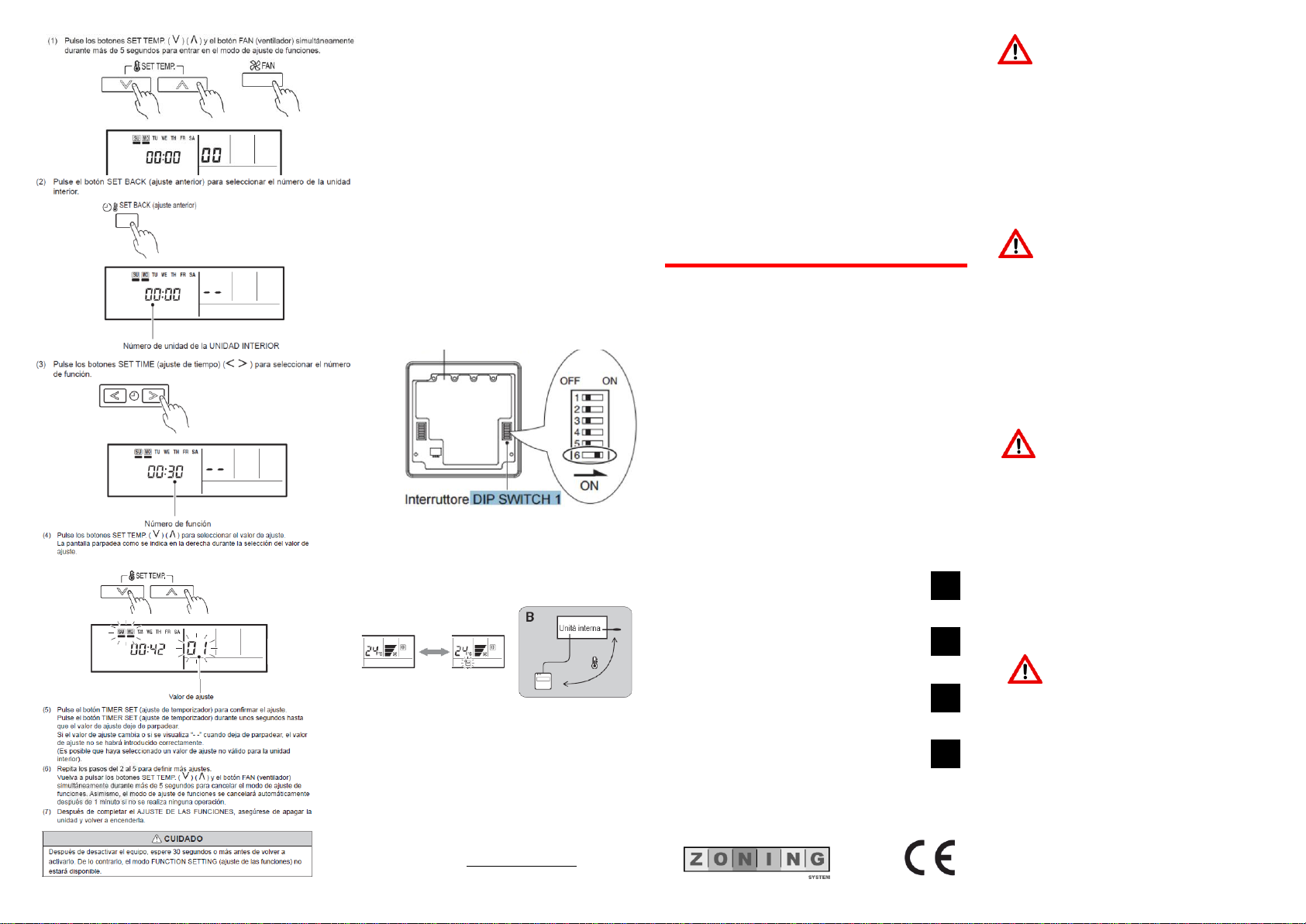
2.Importante: Conectar la sonda NTC de la central y ubicar en el retorno. En caso contrario el sistema no funcionará correctamente.
3.Conecte el interface con la central de control del Zoning. Salida Rs485 AB. Respetar la polaridad entre A y B.
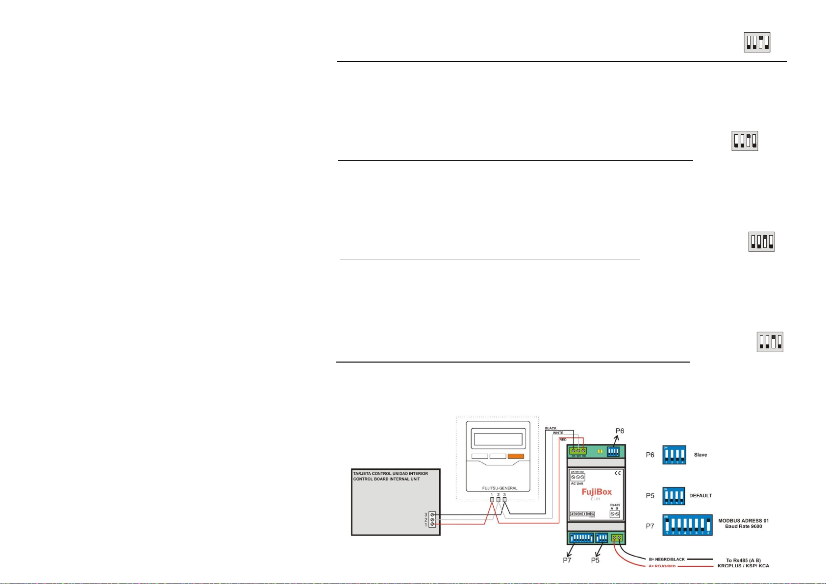
4.Configurar los switch del interface. P5, P6 y P7 según figura adjunta.
5.Conectar los bornes 1 2 3 del interface con el mando de la máquina FUJITSU-GENERAL y conectar el mando a los bornes 1 2 3 de la
placa de la unidad interior, según esquema adjunto.
6.Haga la puesta en marcha del sistema normalmente, el sistema debe empezar a funcionar.
KRCPLUS Seleccionar modo INTERFACE
KSP/KCA Posicionar SW1 de la central
WIRING AND SETTING
1.Install the Zoning system as usual. See corresponding manual.
2.Important: It is obligatory to install the NTC sensor of the central. Install it in the exhaust air of the unit.
3.Connect the intterface with the Zoning control panel. Output Rs 485 AB. Keep the same polarity between A and B
4.Set the micro-switches of the interface. P5 Set as the figure above. P6 leave as default.
5.Connect 1 2 3 terminals of upper-left connector of the interface to 1 2 3 terminal of the FUJITSU-GENERAL thermostat. Then connect it
to the control board of the internal unit. See attached figure.
6. Make the start-up of the zoning system as usual. The system should start working normally.
KRCPLUS Select INTERFACE mode
KSP/KCA Select Sw1 of the control panel as follows
INSTALACIÓN
Desconecte el aire acondicionado de la red eléctrica.
Fije el interfaz a la pared junto a la unidad interior del aire acondicionado
(respete las instrucciones de seguridad anteriores).
Conecte el interfaz y la unidad interior del aire acondicionado, siga las
instrucciones del diagrama de página siguiente.
Conecte el bus RS485 al conector RS485 del interfaz. Respete la polaridad.
Tape la unidad interior del aire acondicionado y vuelva a conectarlo a la red
eléctrica.
Siga las instrucciones de la página siguiente para configurar la interfaz a
través de los micros interruptores.
IMPORTANTE: El cable a usar para la conexión del Fujibox al bus 1 2 3 puede ser
cualquier cable de dos hilos, la distancia máxima para el bus P1 P2 es de 500 metros,
consulte el manual del aire acondicionado para más detalles..
INSTALLATION
Disconnect the Air Conditioner from Mains Power.
Fix the interface beside the AC indoor unit (wall mounting) (respect the safety
instructions given above).
Connect the interface and the AC indoor unit following the instructions of the
diagram below.
Connect the RS485 bus to the connector RS485 of the interface.
Close the AC indoor unit and reconnect it to Mains Power.
Follow the instructions of the next page to configure the interface through on-
board DIP-switches.
IMPORTANT: Any type of 2 wire-parallel cables can be used to connect the FujiBOX with
the 1 2 3 bus, the maximum distance for this bus it is 500 m. Please check the Air Handling
Unit manual for more information.
INSTALLATION
Déconnecter le climatiseur du réseau électrique.
Fixer la passerelle au mur, près de la unité intérieur du gainable.
Brancher la passerelle et l’unité intérieure Suivre les instructions du schéma ci-
joint.
Brancher le bus 485 au connecteur 485 de la passarelle. Respecter la polarité.
Fermer la unité interieur et brancher de nouveau au réseau électrique.
Suivre les instructions du schéma ci-joint pour la configuration de la passerelle et
des micro-switches.
IMPORTANT: On peut utiliser n’importe quel câble parallèle de 2 fils pour la connection du
FujiBOX et du bus 1 2 3, la distance maxime pour cet bus c’est de 500 m. Consulter la notice
d’installation du climatiseur pour plusieurs détails.
INSTALLAZIONE
Scollegare l’unità trattamento d’aria (UTA) dalla rete elettrica.
Fissare l’interfaccia vicino all’unità interna con delle viti (staffe poste sulretro)
o utilizzare una barra DIN (rispettare le istruzioni di sicurezza.)
Collegare l’unità interna e l’interfaccia, seguendo le istruzioni dello schema
allegato.
Collegare il bus RS485 al morsetto RS485 dell’interfaccia. Rispettare la
polarità.
Collegare l’UTA alla rete elettrica.
Seguire le istruzioni nella pagina successiva per la configurazione dei
microswitch dell’interfaccia.
IMPORTANTE: L’allungamento o accorciamento del cavo di connessione incluso nella
interfaccia può causare un funzionamento non corretto. Mantenere il cavo di connessione il
più lontano possibile dal cablaggio elettrico e dal cavo di messa a terra, Non avvolgere
insieme
BRANCHEMENT ET CONFIGURATION
1.Installer normalement le système de zones. Voir la notice correspondant:
2.Important : C’est obligatoire de brancher la sonde NTC de la centrale, et la placer dans la reprise d’air.
3.Brancher la passerelle avec la centrale Zoning correspondant. Sortie Rs485 AB. Respecter la polarité entre A et B.
4.Configurer les switch de la passerelle P5, P6 et P7 selon schéma ci-joint.
5.Brancher les bornes 1 2 3 de la passerelle à la télécommande du FUJITSU-GENERAL, et brancher cette télécommande aux bornes
1 2 3 de l’unité intérieur selon schéma ci-joint.
6.Faire la mise en route normalement, le système doit commencer à fonctionner.
KRCPLUS Choisir le mode INTERFACE
KSP/KCA Placez le SW1 de la centrale
CONNESSIONE È CONFIGURAZIONE
1. Installare il sistema a zone normalmente. Vedere i manuali corrispondenti.
2. Importante: È obligatiorio d’installare la sonda NTC della centralina nella ripresa d’aria.
3. Collegare l’interfaccia con la centralina di controllo Zoning. Uscita Rs485 AB. Rispettare la polarità tra A e B.
4. Configurare gli switch dell’interfaccia. P5, P6 e P7 secondo schema allegato.
5. Collegare il morsetto 1 2 3 della interfaccia con il comando di FUJITSU-GENERAL, e collegare questo comando con i morsetti
1 2 3 della scheda elettronica dell’unità interna.
6. Accendere normalmente. Il sistema deve funzionare correttamente.
KRCPLUS Scegliere il modo INTERFACE
KSP/KCA Scegliere nel Sw1 della centralina