Madel FOK-EIS-180-MF Series User manual

1
01/19
FOK-EIS-180 Fire dampers CE
EN 15650:2010
M A
D
E
L
â
European Test Standard, EN 1366-2
(Fire resistance tests for service installations –
Part 2: Fire dampers)
European Classification Standard, EN 13501-3
(Fire classification of construction products and building
elements –
Part 3: Classification using data from fire resistance tests on
products and elements used in building service installations:
fire resisting ducts and fire dampers)
European Standard for CE Marking, EN 15650
(Ventilation for buildings. Fire dampers)
European Test Standard, EN 60529:1991
(Degrees of protection provided by enclosures (IP Code))
European Test Standard EN 1751
(Ventilation for buildings –Air terminal devices –
Aerodynamic testing of dampers and valves)
International Test Standard ISO 10294-4
(Fire resistance tests –Fire dampers for air distribution systems
Part 4: Test of thermal release mechanism)
•The fire dampers FOK-EIS-180 work as a separator
between two sectors of fire and ensure the same fire
resistance that the structural elements of
compartmentalisation,which limits the risk of spreading
of fire by interior of the building.
•FOK-EIS-180 fire dampers are according with the
following standards:
•The casing is made of galvanised steel, and joined by
clinching system (cold forming the material).
•It incorporates a solid perimeter frame to facilitate the
sealing between the fire damper and support
construction.
•The housing is made from galvanized steel. It has a
symmetrical design that allows wall mounting
regardless of air flow.
•The blade is made of ceramic material resistantto
high temperaturesand abrasion.
•These dampers meet the conditionsrequired for the
symbol (S) to cold smoke seal.
•The airtightnessto the passage of cold smoke is
achieved through a joint between the perimeter of the
housing and the blade.
•For high temperatures,the damper is equipped with
an expanding intumescent seal, forming a paste that
prevents the passage of hot air and smoke from one
side of the damper to another.
•The operating devices of the dampers is automatic
shooting by means of a thermal fuse calibrated at 72°C
to activatethe closure when reaches that temperature.
Reset is manual except for motorized dampers.

DECLARATION OF PERFORMANCES
2
01/19
V01/19
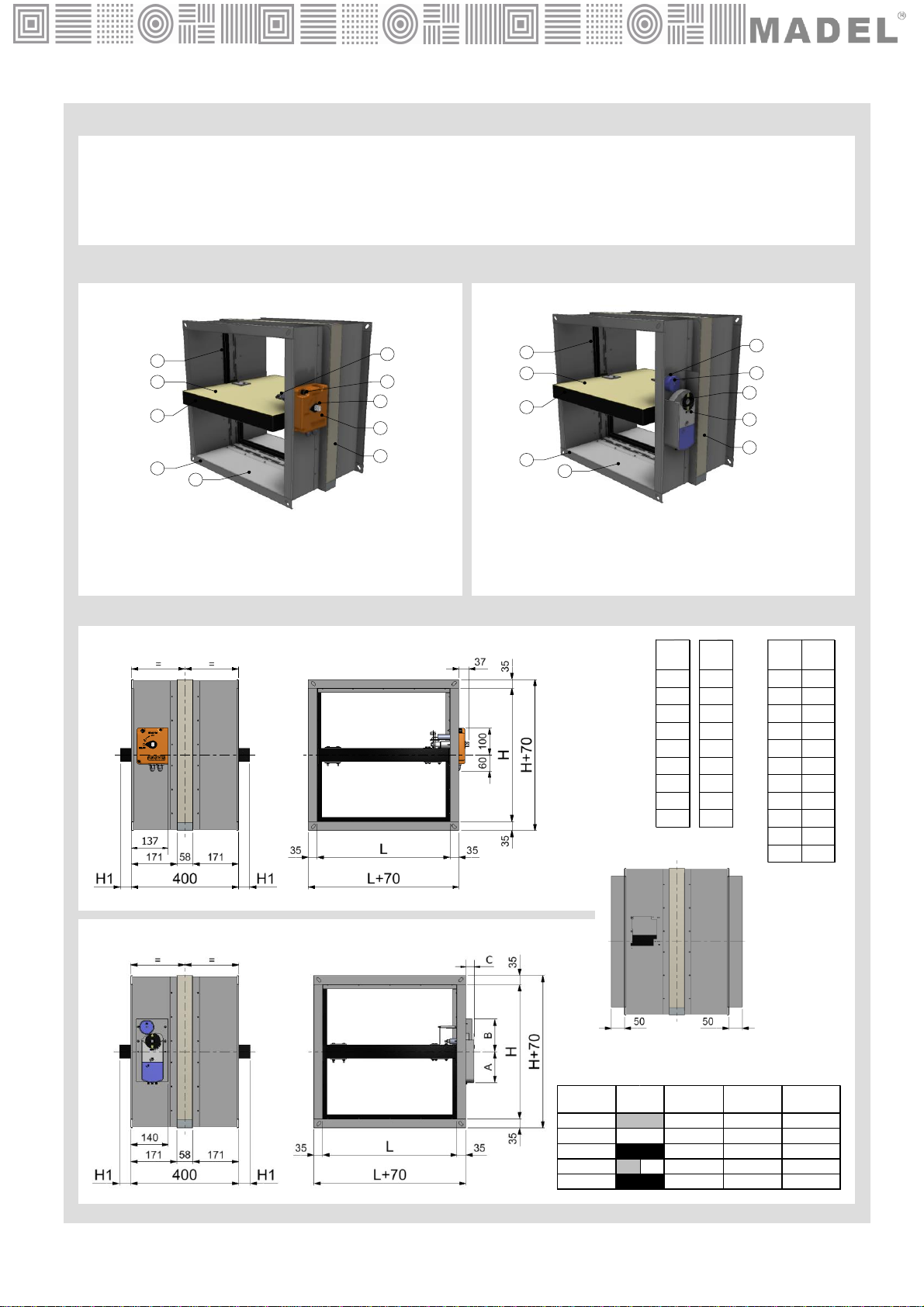
Fire damper “FOK-EIS-180”
Madel Air Technical Diffusion S.A,
C/ Pont de les Bruixes P-5, P.I. La Gavarra, 08540 CENTELLES (Barcelona)
To prevent fire and reduce smoke spreading from one fire compartment to
another through the air ductwork system which may penetrate fire separating
vertical compartments, according to Standard EN 15650:2010 (annex ZA.1).
System 1, according to Construction Products Regulation nº 305/2011
APPLUS - 0370
Performed tasks:
- Determination of the product type on the basis of type testing (including
sampling), type calculation,tabulated values or descriptive documentation of
the
product;
- Initial inspection of the manufacturing plant and of factory production control;
- Continuous surveillance, assessment and evaluation of factory production
control.
System 1
Certification number: 0370 –CPR –1392
Test report:
09/100022-20, 14/8629-947, 17/12815-16, 18/17552-1207
18/12815-700, 18/12815-2189
6. Performances (EN 15650 :2010):
Performances
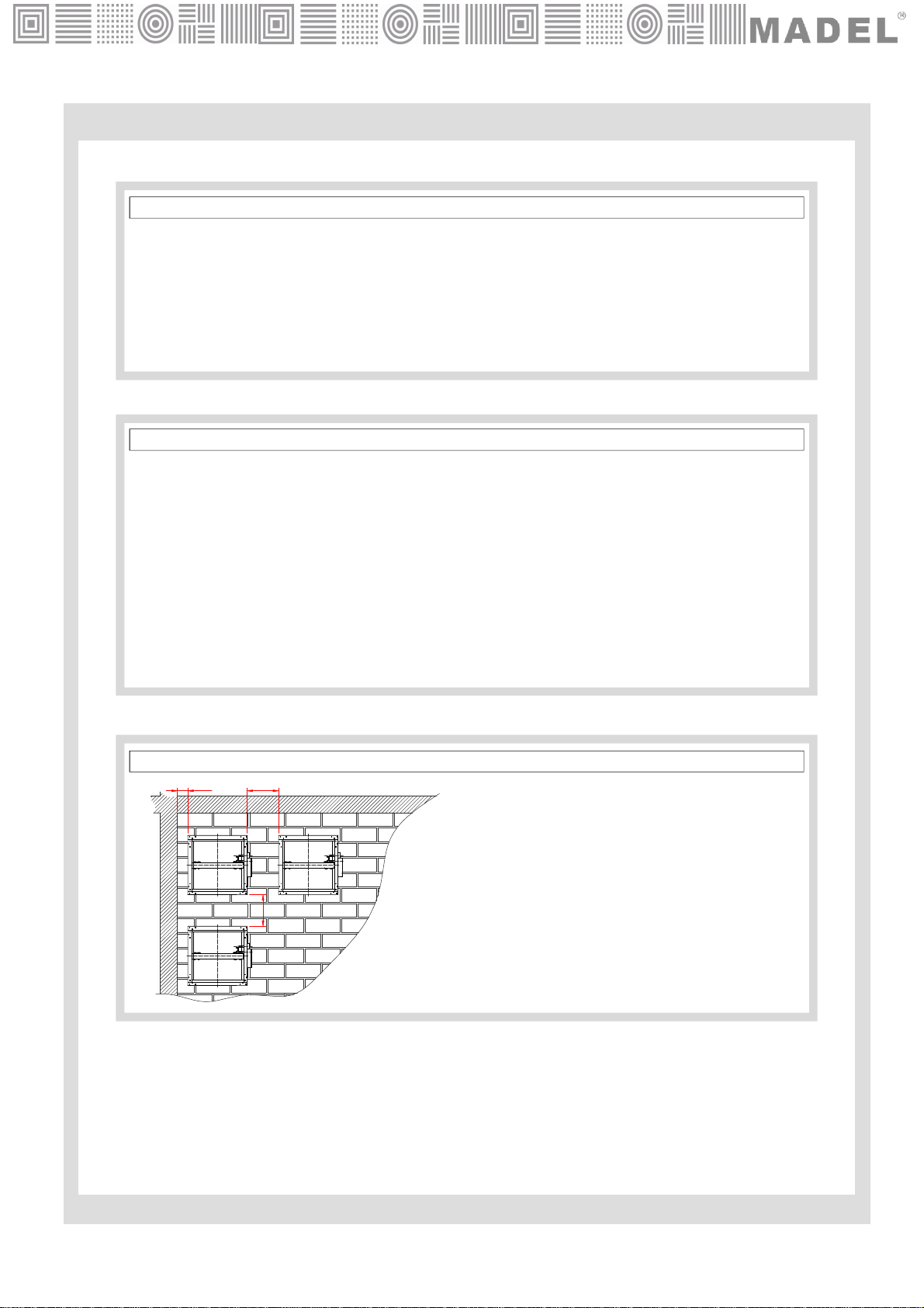
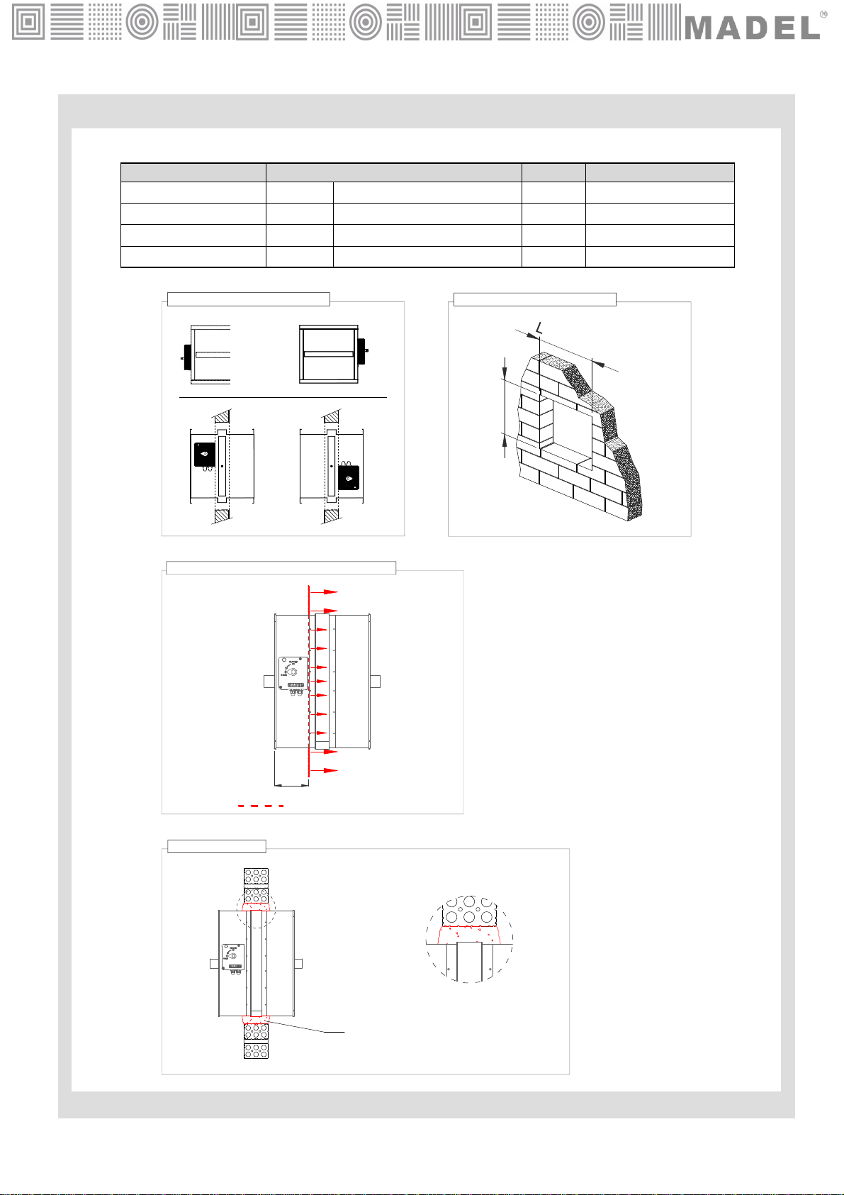
Dimensions Type Wall Type of
installation Mechanism
orientation Class
Rigid wall Brick wall/ Reinforced
concrete
≥150 mm Built-in 0-180º EI 180 (vei↔o) S (500Pa)
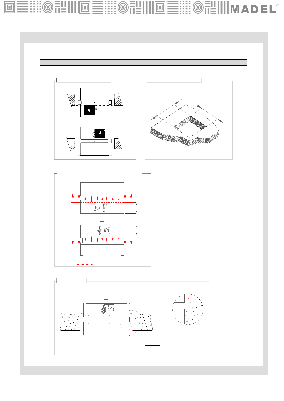
Rigid floor Hormigón armado
≥200 mm Built-in 0-360º EI 180 (vei↔o) S (300Pa)
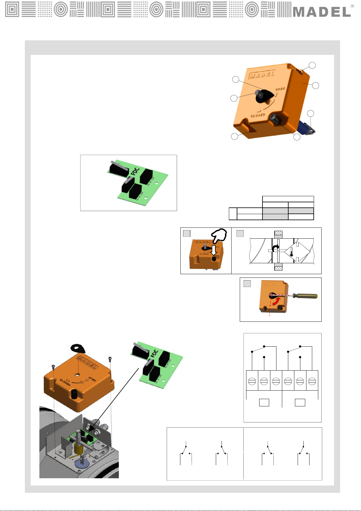
Sensing element load bearing capacity
Sensing element response temperature
Closure time
50 cycles
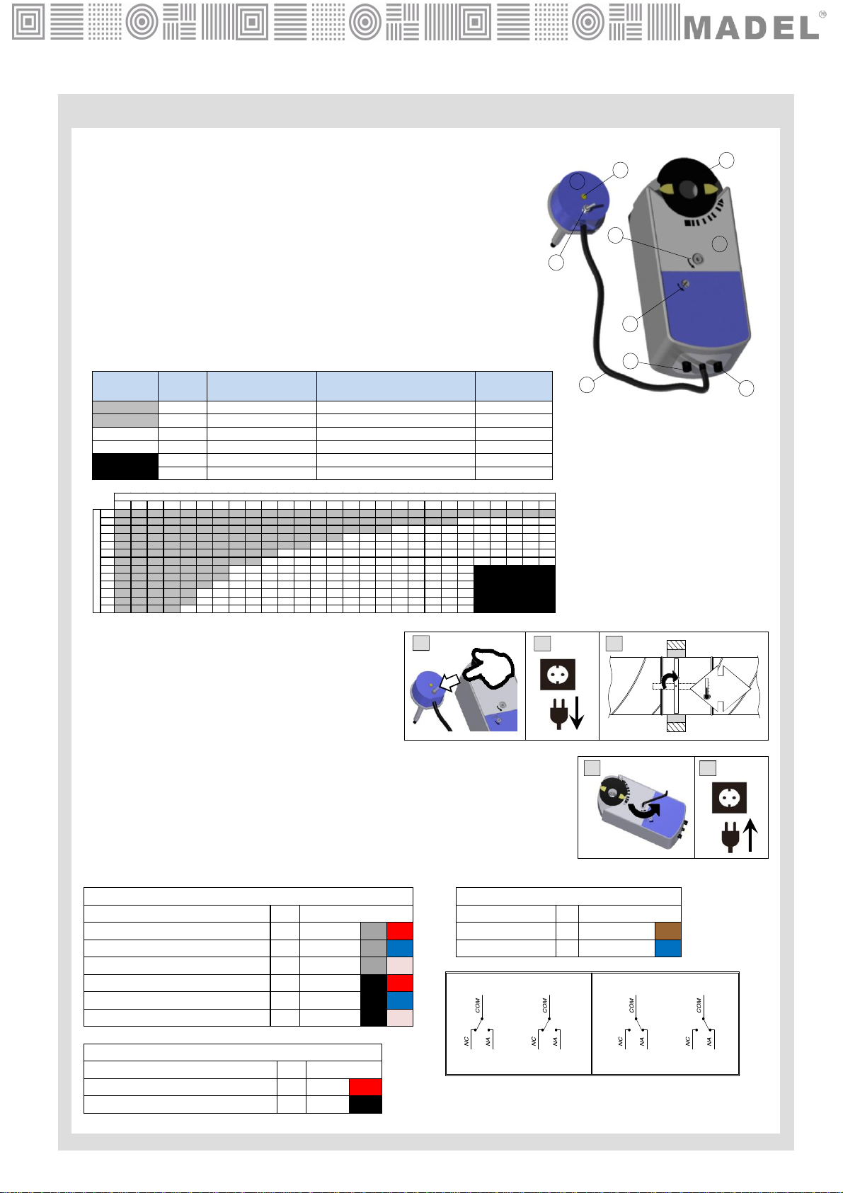
…- /MA/ - 300 cycles, …-/MAF/ - 300 cycles,
…- /MFS…V/ - 10.200 cycles, …- /MFB…V/ - 10.200 cycles
Sensing element response temperature and load bearing capacity
Opening and Closing cycle
DECLARATION OF PERFORMANCE (Nº 0370-CPR-1392)
Approved
Approved
Approved
Joan Arcarons Alibés
(Technical Director)
Durability of operationalreliability according to 15650:
7. The performances of the product identified in point 1, are inline with the declared performance in point 6.
This declarationof performance is issued under the responsibility of the
manufacturer listed in point 2.
Signed forand on behalf ofthe manufacturer:
Centelles, 10/01/19
Nominal activation conditions/ sensitivity:
Response delay according to EN 1366-2: Approved
Durability of response delay according to EN1366-2:
4. Assessment of conformity system:
Operational reliability according to EN 1366-2
3. Uses to:
2. Name and address of manufacturer:
1. Product and identificationname:
Essential characteristics
Cycling (opening and closing) on fire test.
Cycling (opening and closing) according to Standard for CE Marking
5. Certification body:
200 x 200
a
1500 x 800

CLASSIFICATION
PARTS
DIMENSIONS
6. Brida de conexión a 90º
7. Mecanismo /MA/
8. Indicador de posición
9. Pulsador de accionamiento
10. Fusible térmico a 72ºC
FOK-EIS-180-MA
FOK-EIS-180-MF…
3
01/19
L
200
250
300
350
400
450
500
550
600
700
800 200
250
300
350
400
450
500
550
600
700
800
(mm) H
(mm) H1
(mm)
-
-
-
-
-
25
50
75
100
150
200
900
1000
1100
1200
1300
1400
1500
L
(mm)
FOK-EIS-180 /CR …
FOK-EIS-180-MA
5
7
9
10
8
2
4
61
3
8
2
4
61
3
5
7
9
10
FOK-EIS-180-MF…
Ref. A
(mm)
B
(mm)
C
(mm)
MFS…115 121 32
MFS…115 121 32
MFS…191 121 40
MFB…150 121 25
MFB…160 121 32
S/ dim.
FOK-EIS-180 Rectangular damper 90º angled flange connection to the ducts.
…-MA Manual resetting damper. Is not necessary to open the box device.
…-MF…Damper operated by an actuator with switch off device at 24 or 230V.
1. Casing
2. Blade
3. Airtightness seal
4. Intumescent seal
5. Perimetral frame
6. 90º angled flange
7. Operating device /MA/
8. Position indicator
9. Test button
10. Thermal fuse 72ºC
1. Casing
2. Blade
3. Airtightness seal
4. Intumescent seal
5. Perimetral frame
6. 90º angled flange
7. Actuator /MF…/
8. Position indicator
9. Test switch
10. Thermoelectrical fuse 72ºC

OPERATING DEVICES
…-/MA/ Manual resetting damper. Automatic shooting by
means of a thermal fuse calibrated at 72 °C.
Standard:
- Thermal fuse 72ºC
- Manual test button
- Manual resetting
- Position indicator
- IP42 protection
Optional…- /PIF/ Closed switchesdevice
1
2
23
4
5
6
fig. MA
fig. PIF
Close (unlocking)
•Manual: Pressing the unlocking button (A)
•Automatic: The fusible link reaches 72ºC (B)
•Remote: -
Open (resetting)
•Manual: Turning counterclockwise 90º the manual resetting axe using a
tool with a smaller diameter than 8mm (C)
•Automatic: -
Electrical connection *Switches normally closed contacts
COMNFNO COMNFNO
FC DC
Closed damper
signal Open damper
signal
4
01/19
CONTACT "FC"
COM
NO NF
B. OPEN DAMPERA. CLOSED DAMPER
CONTACT "DC"
COM COM COM
NO NF NO NF NO NF
CONTACT "FC" CONTACT "DC”
72ºC
AB
C
0º
90º
1. Plastic command cover
2. Screws for cover attachment
3. Manual test button
4. Position indicator
5. Manual resetting axe.
6. Thermal fuse 72ºC
200…1000 1050…1500
200…550 - /MA/ - /MA/
600…800 - /MA/ -
L
H

1. Actuator
2. Position damper indicator
3. Manual resetting
4. Manual lock
5. Plug closed switches cable
6. Thermoelectrical fuse cable
7. Power supply cable
8. Thermoelectrical fuse 72ºC
9. Manual testswitch
10. LED status fusible indicator
2
1
8
4
3
5
7
6
10
9
fig. MFS…V
Close (unlocking)
•Manual: Pressing the manual test switch (A)
•Remote: By interrupting the power supply (B)
•Automatic: The fusible link reaches 72ºC (C)
Open (resetting)
•Manual: Turning counterclockwise the manual resetting with allen key (D)
To keep the blade open, lock by manual lock
•Automatic: By supplying the power supply (E)
Electrical connection
•Fixed switching points at 5º and 80º
•• Fixed switching point at 5º to contact “A”
•• Fixed switching point at 80º to contact “B”
S1
S2 S3
S4
S5 S6
S1
S2 S3
S4
S5 S6
A. CLOSED DAMPER
CONTACT “B”
CONTACT “A”
B. OPEN DAMPER
CONTACT “B”
CONTACT “A”
5
01/19
OPERATING DEVICES
…- /MFS…/Damper operated by remote control by means of an
actuatorwith switch off device at 24 or 230V or a
thermal fuse calibrated at 72 °C. .
Standard: - Internal and external thermoelectrical fuse 72ºC
- Automatic resetting
- Automatic closing by fuse 72ºC
- Remote closing by interruption of power supply
- Manual test switch
- LED status fusible indicator
- Position damper indicator
- Closed switches
- IP54 Protection
72ºC
AB C
DE
AUXILIARYSWITCHES CABLE
MEANING Nº COLOR
Switch "A" input S1 grey/ red
Switch "A" normally-closed contact S2 grey/ blue
Switch "A" normally-open contact S3 grey/ pink
Switch "B" input S4 black/ red
Switch "B" normally-closed contact S5 black/ blue
Switch "B" normally-open contact S6 black/ pink
ACTUATOR 24VCA/24…48VCC
MEANING Nº COLOR
Systempotential 24VCA/ 24…48VCC 1 red
Systemneutral 2 black
ACTUATOR 230VCA
MEANING Nº COLOR
Line 230VCA 3 Brown
Neutral 4 Blue
200 250 300 350 400 450 500 550 600 650 700 750 800 850 900 950 1000 1050 1100 1150 1200 1250 1300 1350 1400 1450 1500
200
250
300
350
400
450
500
550
600
650
700
750
800
L
H
Reference
a/size Torque Voltage Consumption Time
Open/ Close
MFS24V 4 Nm CA 24V, CC 24/48V 3,5W (running)/ 2W (stationary) 90s/ 15s
MFS230V 4 Nm CA 230V 4,5W (running)/ 3,5W (stationary) 90s/ 15s
MFS24V 7 Nm CA 24V, CC 24/48V 3,5W (running)/ 2W (stationary) 90s/ 15s
MFS230V 7 Nm CA 230V 4,5W (running)/ 3,5W (stationary) 90s/ 15s
MFS24V 18 Nm CA 24V, CC 24/48V 5W(running)/ 4W (stationary) 90s/ 15s
MFS230V 18 Nm CA 230V 6W (running)/ 4W (stationary) 90s/ 15s

OPERATING DEVICES
6
9
10
5
7
4
3
2
1
fig. MFB…V
6
01/19
72ºC
BCA
E
D
…- /MFB…/Damper operated by remote control by means of an
actuatorwith switch off device at 24 or 230V or a
thermal fuse calibrated at 72 °C. .
Standard: - Internal and external thermoelectrical fuse 72ºC
- Automatic resetting
- Automatic closing by fuse 72ºC
- Remote closing by interruption of power supply
- Manual test switch
- LED status fusible indicator
- Position damper indicator
- Closed switches
- IP54 Protection
1. Actuator
2. Position damper indicator
3. Manual resetting
4. Manual lock
5. Plug closed switches cable
6. Thermoelectrical fuse cable
7. Power supply cable
8. Thermoelectrical fuse 72ºC
9. Manual testbutton
10. LED status fusible indicator
Close (unlocking)
•Manual: Pressing the manual test switch (A)
•Remote: By interrupting the power supply (B)
•Automatic: The fusible link reaches 72ºC (C)
Open (resetting)
•Manual: Turning counterclockwise the manual resetting with allen key (D)
To keep the blade open, lock by manual lock
•Automatic: By supplying the power supply (E)
Electrical connection
•Fixed switching points at 5º and 80º
•• Fixed switching point at 5º to contact “A”
•• Fixed switching point at 80º to contact “B”
S1
S2 S3
S4
S5 S6
S1
S2 S3
S4
S5 S6
A. CLOSED DAMPER
CONTACT “B”CONTACT “A”
B. OPEN DAMPER
CONTACT “B”CONTACT “A”
MEANING Nº BFL/ BFN BF
Switch "A" input S1 Violet White
Switch "A" normally-closed contact S2 Red White
Switch "A" normally-open contact S3 White White
Switch "B" input S4 Orange White
Switch "B" normally-closed contact S5 Pink White
Switch "B" normally-open contact S6 Grey White
ACTUATOR 24VCA/24…48VCC
MEANING Nº COLOR
Neutral 1 Black
Systempotential 24VCA/ 24…48VCC 2 Red
ACTUATOR 230VCA
MEANING Nº COLOR
Neutral 1 Blue
Line 230VCA 2 Brown
200…1250 1300…1500
200…500
550…800
L
H
Reference
a/size Torque Voltage Consumption Time Open/
Close
MFB24V 9 Nm CA 24V/ CC 24/48V 4W (running)/ 1,4W (stationary) 60s/ 20s
MFB230V 9 Nm CA 230V 4,5W (running)/ 3,5W (stationary) 60s/ 20s
MFB24V 18 Nm CA 24V/ CC 24/48V 7W (running)/ 2W (stationary) 120s/ 16s
MFB230V 18 Nm CA 230V 8,5W (running)/ 3W (stationary) 120s/ 16s

GENERAL POINTS
•The minimum distance between fire dampers and
construction elements will be 75mm.
•The minimum distance between fire dampers will be
200mm.
MINIMAL DISTANCES (a/ European Standard EN 1366-2)
•The MADEL fire dampers are classified for the supporting constructions described in this manual or similar
supporting constructions with a same or superior fire resistance (more thickness/ density or number of
boards (according to EN 1366-2).
•Any variation in supporting construction as described in the previous point, different sealing or type of
installation regarding this document, the fire damper will not comply the classification.
•Install the fire damper with the blade closed and avoid excessive pressures in its casing.
•Avoid to project materials to the interior of the tunnel.
•Avoid vibrations in the installation.
•Check the opening and closing after the installation.
•The inner dimension of the air ducts can not be smaller than inside dimension of the damper.
SUPPORTING CONSTRUCTION AND INSTALLATION
•Avoid to store outdoor.
•Avoid the contact with liquids.
•Avoid impacts.
•Not to put loads on the blade.
•Not to use the fire damper for a different purpose to which it’s been designed.
•Use the operating device for open/ close the damper, never through the blade.
STORAGE AND HANDLING
7
01/19
200
75
200

INSTALLATION
1. Operating device position
- RIGID WALL
8
01/19
nominal + 150
H
nominal
+ 150
±20
±20
0º 180º
2. Support construction opening
4 .Sealing
Sealing: Mortar
DETAIL A
A
3. Starting plane of supporting construction
144
Starting plane of supporting construction/ sealing
Dimensions Supporting construction Sealing Classification
200 x 200 to 1000 x 600 Rigid wall Brick wall ≥110mm Mortar EI180 (vei↔o) S (300Pa)
200 x 200 to 1000 x 600 Rigid wall Reinforced concrete ≥110mm Mortar EI180 (vei↔o) S (300Pa)
>1000 x 600 to 1500 x 800 Rigid wall Brick wall ≥150mm Mortar EI180 (vei↔o) S (500Pa)
>1000 x 600 to 1500 x 800 Rigid wall Reinforced concrete ≥150mm Mortar EI180 (vei↔o) S (500Pa)

INSTALLATION
- RIGID FLOOR
9
01/19
3. Starting plane of supporting construction
4. Sealing
Sealing: Mortar
A
DETAIL A
144144
1. Operating device position 2. Support construction opening
Hnominal + 150±20
Lnominal + 150
±20
Starting plane of supporting construction/ sealing
Dimensions Supporting construction Sealing Classification
200 x 200 to 1500 x 800 Rigid floor Reinforced concrete ≥200mm Mortar EI180 (hoi↔o) S (300Pa)

SPECIFICATION TEXT
CODIFICATION
10
01/19
FOK-EIS-180 - /CR - H - MA - /PIF/ dim. L x H
1 2 3 4 5 6
(Manual)
Supply and mounting of rectangular fire damper
classedEIS-180 in accordance to the European
Standard EN 13501-3 and certified CE according to
EN 15650, series FOK-EIS-180-MA dim. 500 x 300
Operated by means of a manual operating device.
Built in galvanized steel and refractory material.
Thermal fusible link at 72ºC. An expanding joint
together an air-tightness joint, as much prevent the
propagationof smoke to high as to low temperature.
Manufacturer MADEL.
(Motorized)
Supply and mounting of rectangular fire damper
classedEIS-180 in accordance to the European
Standard EN 13501-3 and certified CE according to
EN 15650, series
FOK-EIS-180-MFS230V dim. 500 x 300
Operated by means of a motorized operating device.
Built in galvanized steel and refractory material.
Thermoelectricfusible at 72ºC. An expanding joint
together an air-tightness joint, as much prevent the
propagationof smoke to high as to low temperature.
Manufacturer MADEL.
1. Product
2. Operating device
- (90º angled frame) (by default)
- /CR/ (50mm straight flange)
3. Orientation
-H(Blade axe parallel to the smaller size) (by default)
-V(Blade axe parallel to the higher size)
4. Operating device -MA (Manual)
-MFS (Siemens actuator)
-MFB (Belimo actuator)
5. Accessories -/PIF/ (Open-closed switches device)
6. Dimensions (mm) -L(Length of the base)
-H(Height of the operating device side)

TECHNICAL DATA
FOK-EIS-180
FREE AREA FOR THE AIR PASS (m2) / CORRECTION VALUES FOR DPt, Lwa
11
01/19
100
1,070
-24
0,007
0,013
0,805
0,019
-18
0,025
-18
0,675
-16
0,735
0,655
-14,75
0,031
600 Kr
Lwa = Lwa1 + Kf
Kf
Afree
300
400
500
Kf
Afree
Kf
Kr
Afree
Kr
Afree
Kf
Kr
200
H
Kr
Kf
Afree
L
0,630 0,535 0,470 0,425 0,4 0,375 0,365 0,360 0,345
-0,25-10,25 -6,5 -3,5 -2,25 2
134
0,875
-11,75
0,065
0,121
0,625
0,177
-7,25
0,233
0,450
0,530
0,289
0,035 0,056 0,078 0,099
0,740
0,082
0,108
0,585
0,655
0,134
-14,5 -10,5
0,067
0,670
-11,75
0,083 -8,5
0,790
0,051
-17,25
0,715
-13
-9 -6,25
0,150
0,520
-6
0,186
0,191
0,485
-3,5
0,237
0,685
0,114
-10,5
0,595
0,645
0,145
-8,75
0,550
0,930
-17,5
200
1,075
-21,75
0,019
300
0,03
400
0,920
-15,5
0,042
500
0,895
-14
0,053
0,143 0,164 0,186 0,207
0,6
0,240
0,316
-2,25
0,415
-0,25
0,490
0,392
-4 -3,25
0,275
0,440
-0,75
0,341
-2
0,615
0,209
-6
0,525
-5
-1 -0,5
0,358
0,410
0,75
0,444
0,399
0,4
2,5
0,495
0,59
0,270
-3,75
0,480
0,58
0,303
-3
0,470
800
0,855
-9,5
0,088
700
0,865
-10,25
0,077
600
0,845
-8,75
0,1
900 1000
0,830
-8
0,111
Dpt(Pa)
0,33
4
0,22
-0,45
0,44
0,39
2,25
0,54
0,57
0,33
-2,75
0,46
1100
0,815
-7,5
0,12
0,32
4
0,25
-0,4
0,483
0,38
2
0,599
0,56
0,367
-2,5
0,450
1200
0,8
-7,25
0,13
0,302
4
0,26
-0,35
0,518
0,375
1,75
0,643
0,545
0,39
-2,25
0,445
1300
0,785
-7
0,14
0,029
4
0,28
-0,325
0,558
0,36
1,5
0,693
0,53
0,42
-2
0,43
1400
0,77
-6,75
0,155
0,27
4
0,31
-0,3
0,598
0,345
1,25
0,742
0,515
0,45
-1,75
0,415
1500
0,76
-6,5
0,166
0,635
-14,75
0,037
700 Kr
Kf
Afree 0,58 0,5 0,44 0,4 0,37 0,35 0,33 0,32 0,31
-0,25-10,25 -6,5 -3,5 -2,25 21 34
0,34
0,160,099 0,22 0,28 0,460,4 0,53 0,59 0,3
4
0,65 0,28
4
0,715 0,265
4
0,767 0,25
4
0,82 0,24
4
0,88
0,605
-14,75
0,043
800 Kr
Kf
Afree 0,56 0,49 0,42 0,38 0,35 0,32 0,31 0,3 0,29
-0,25
-10,25 -6,5 -3,5 -2,25 2
134
0,40,1860,115 0,25 0,32 0,54
0,47 0,61 0,68 0,27
4
0,75 0,26
4
0,83 0,245
4
0,88 0,23
4
0,95 0,22
4
1,02

TECHNICAL DATA
FOK-EIS-180
700
500
55
Vf (m/s)
2500
1800
Q (m3/h)
1.5 23
14000
17000
24000
12000
10000
4500
5500
3000
3500
6500
8000
4 5 6789
0,4
0,2
Kr
1
0,8
0,6
10
2
35 40 45 50
L wa1 = ( dB (A))
11
5
3
4
2
Vf (m/s)
1.5 2 3 45678910
0.15
0,02
DPt ( Pa )
30
15
20
10
100
60
80
40
0.06
0.05
0,03
0.04
0.08
0.1
0.8
A free(m )
0.3
0.2
0.6
0.4
0.5
1
1
1300
1600
400
200
300
1100
900
12
01/19
FREE VELOCITY, PRESSURE DROP AND SOUND POWER LEVEL
This manual suits for next models
7
Table of contents
Other Madel Fire And Smoke Damper manuals