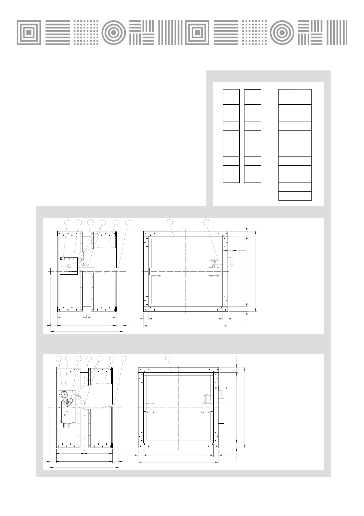
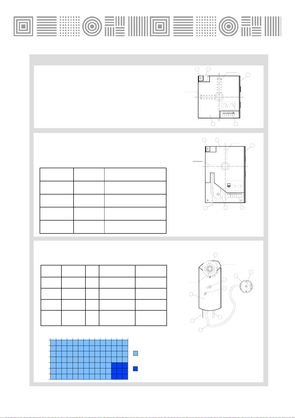
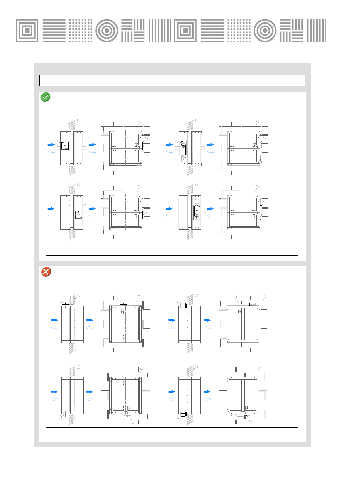
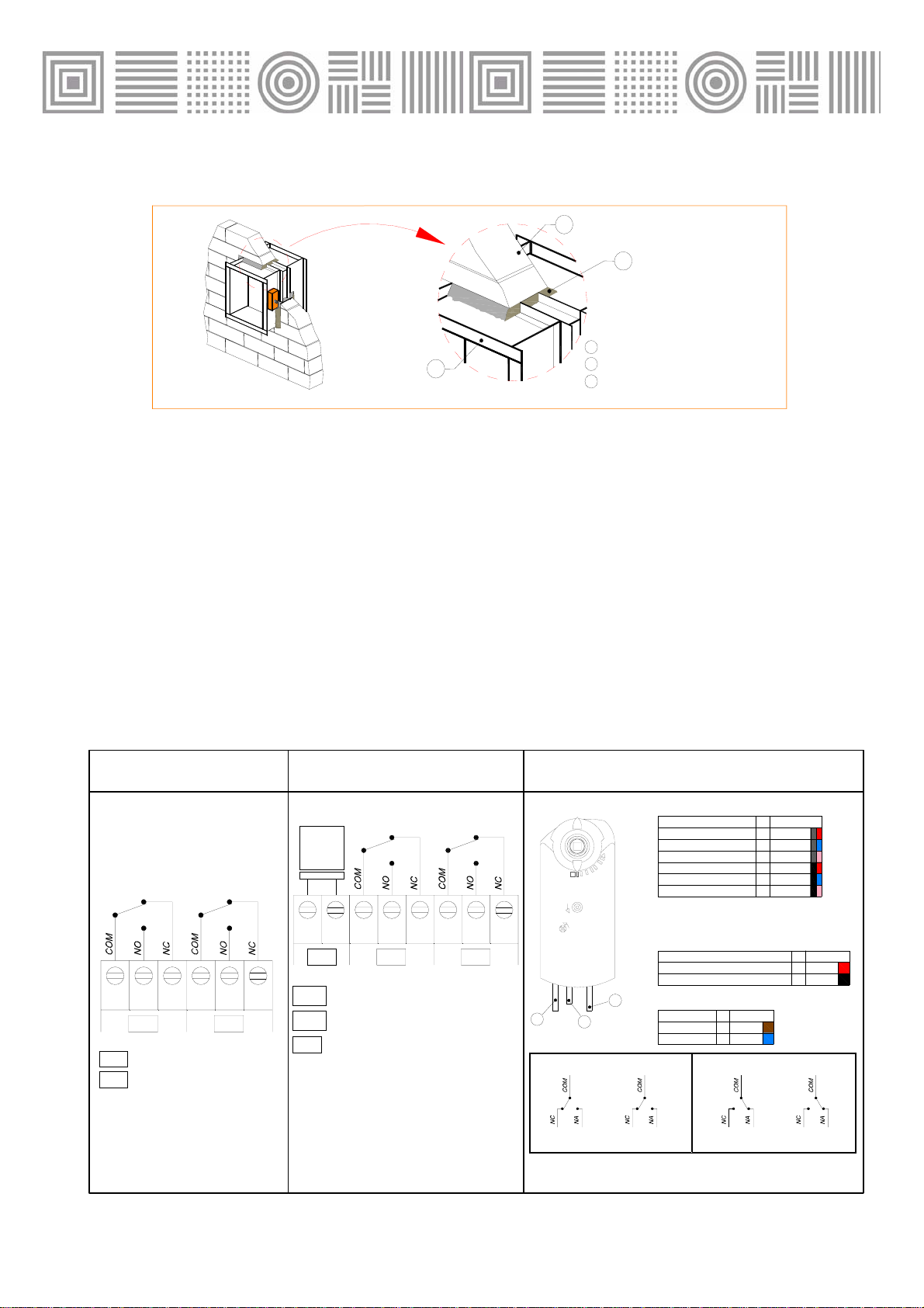
Madel FBK-EIS-120 Quick start guide

MADEL
®
14/11
FBK-EIS-120 fire dampers EIS-120
MADEL
®
Patented
The fire dampers FBK-EIS-120 work as a separator
between two sectors of fire and ensure the same
fire resistance that the structural elements of
compartmentalisation, which limits the risk of
spreading of fire by interior of the building.
These dampers can be installed in the wall *and are
classified as follows:
Testing European Standard EN 1366 -2
Classification European Standard EN 13501-3
Classified EI 120 ( ho i ↔o) S
(E) Integrity
(I) Insulation
120 minutes fire resistance
(ho) Air direction: horizontal
(i↔o) symmetrical
(S) airtightness
*(to install in the floor, see the FOK-EIS-180 series)
The housing is made from galvanised steel and the
assembly using clinch system. It has a symmetrical
design that allows wall mounting regardless of air flow.
The housing is reinforced, at the height of the blade
with longitudinal angles that give rigidity to the
damper. The blade is made of ceramic material
resistant to high temperatures and abrasion.
These dampers meet the conditions required for the
symbol (S) to cold smoke seal. In case of fire, smoke
poisoning is the leading cause of death.
The airtightness to the passage of cold smoke is
achieved through a joint between the perimeter of the
housing and the blade.
For high temperatures, the damper is equipped with
an expanding intumescent seal, forming a paste that
prevents the passage of hot air and smoke from one
side of the damper to another.
The operating devices of the dampers is automatic
shooting by means of a thermal fuse calibrated at 72 °
C to activate the closure when reaches that
temperature. Reset is manual except for motorized
dampers.

2
CLASSIFICATION
FBK-EIS-120-H Damper with angled flange
connection. Blade parallel to the large side.
FBK-EIS-120-V Damper with angled flange
connection. Blade parallel to the short side.
…-MA Manual resetting damper. Is not necessary to
open the box device.
…-M7F Damper operated by an actuator with switch
off device at 24 or 230v.
MADEL
®
FBK-EIS-120-H-MA
L
200
250
300
350
400
450
500
550
600
700
800 200
250
300
350
400
450
500
550
600
700
800
(mm) H
(mm) H1
(mm)
-
-
-
-
-
25
50
75
100
150
200
900
1000
1100
1200
1300
1400
1500
L
(mm)
FBK-EIS-120-H-M7F
SIZES
400
H
L
35 35
35 35
= =
L + 70
H + 70
H
26 4 1
5
73
H1 H1
-5º
45º
90º
STOP
8
40
35
2
64 15
738
H
L
35 35
35 35
L + 70
H + 70
400
= =
H
H1 H1
1.Housing
2. Blade
3. Airtightness seal
4. Thermal bridge
5. Transmission roads
6. Manual device
7. Driving switch
8. Thermal fuse
1.Housing
2. Blade
3. Airtightness seal
4. Thermal bridge
5. Transmission roads
6. Actuator
7. Test switch
8. Thermal fuse
4/11

3
MADEL
®
OPERATING DEVICES
…-MA Manual resetting damper. Automatic shooting by
means of a thermal fuse calibrated at 72 °C.
Is not necessary to open the box device to reset or to test
the damper.
…-MA /EL/ Manual resetting damper. Automatic shooting by
remote control by means of an elecromagnetement or a
thermal fuse calibrated at 72 °C.
Is not necessary to open the box device to reset or to test the
damper.
…-M7F Damper operated by remote control by means of an
actuator with switch off device at 24 or 230v or a thermal fuse
calibrated at 72 °C.
200
300
400
500
600
200
300
400
500
600
700
800
900
1000
1100
1200
1300
1400
1500
700
800
L(mm)
H (mm)
M7F230V
M16F230V
M7F24V
M16F24V
1. Command support
2. Command cover
3. Screw for cover attachment
4. Button to close rhe damper.
5. Terminal connection of open/closed switches device
1. Actuator
2. Position indicator
3. Manual operation
4. Position lock
5. Connection cable for auxiliary switches
6. Themal fuse cable
7. Power cable connection
8. Thermal fuse
9. Test button
4/11
S1 S2 S3 S4 S5 S6
CLOSED OPEN
S1 S2 S3 S4 S5 S6
OUVERT
FERMÉ
34
5
2
1
S1 S2 S3 S4 S5 S6V+ V-
S1 S2 S3 S4 S5 S6
CLOSED OPEN
V+ V-
FBC/ FBA
FEC/ FEA
3
56
1
2
4
-5º
45º
90º
STOP
7
1
8
2
3
4
5
6
9
4W/FEA/
1.6 W/FEC/
5.5 W/FBA/
3.5 W/FBC/
4W/FEA/
1.6 W/FEC/
5.5 W/FBA/
Closes by electric current.
(VCC 24V/ 48V)
3.5 W/FBC/
Consumption
REF.
ELECTROMAGNET
Closes by electric current.
(VAC 230V)
Closes when current stops.
(VCC 24V/ 48V)
Closes when current stops.
(VAC 230V)
Description
90s / 15s
VAC 5W
18Nm
CC 24V/ 48V
CA 24V
M16F24V
90s / 15s18NmCA 230VM16F230V
90s / 15s7Nm
CC 24V/ 48V
CA 24V
M7F24V
90s / 15s7NmCA 230VM7F230V
Time to
Open / Close
Voltage
90s / 15s
VDC 4W
18Nm
CC 24V/ 48V
CA 24V
M16F24V
90s / 15s
6W
18NmCA 230VM16F230V
90s / 15s
3.5W
7Nm
CC 24V/ 48V
CA 24V
M7F24V
90s / 15s
4.5W
7NmCA 230VM7F230V
Torque
Reférence Consumption
1. Command support
2. Command cover
3. Screw for cover attachment
4. Button to close rhe damper.
5. Electromagnet
OPEN
CLOSED
OPEN
CLOSED
OPEN

4
MADEL
®
MOUNTING PRECAUTIONS
POSITION LOCKING DEVICE
FBK-EIS-120-…-MA FBK-EIS-120-…-M7F
IMPROPER INSTALLATION
2 2
2 2
1
1
1
1
1
1
2
2
1
1
2
2
The dampers have never been installed with the device at the top or at the bottom.
Manual device at the top Motorised device at the top
FBK-EIS-120-…-MA
Manual device at 0º
Manual device at 180º
Motorised device at 0º
Motorised device at 180º
1. Wall
2. Actuator
PROPER INSTALLATION
FBK-EIS-120-…-M7F
The dampers must be installed with the device on the side.
Manual device at the bottom
-5º
45º
90º
STOP
-5º
45º
90º
STOP
1
2
1
2
2
1
2
1
1
2
1
1
2
1
2
2
Motorised device at the bottom
4/11
1. Wall
2. Actuator

5
MADEL
®
MOUNTING PRECAUTIONS
The design of the damper with
driving device shaft offset from the
blade, helps us the connection to the
wall.
To achieve the sectorization, the
damper will be placed with the axis
line of the blade in the work support
(wall).
1
2
3
The damper will not be placed with the axis line of the
blade off-site support (wall) because it would lose the
function of sectorization.
The locking device must be accessible and nothing
impede its work.
WALL MOUNTING
PROPER INSTALLATION
FBK-EIS-120-…-MA
FBK-EIS-120-…-M7F
1
2
3
FBK-EIS-120-…-MA
FBK-EIS-120-…-M7F
IMPROPER INSTALLATION
DISTRIBUTION BETWEEN DAMPER AND CONSTRUCTION ELEMENTS
-The distance between dampers and construction
elements will be 75mm.
-The distance between dampers shall be 200 mm.
20075
200
1. Wall
2. Locking device
3. Axis of the blade
4/11
NOT PROTECTED ZONE

6
MADEL
®
INSTALLATION AND COMMISSIONING
1. DAMPER RECEPTION
Unpack the damper and visually check that has not been damaged during transport.
Do a test at the damper (open / close) to verify that it works correctly .
3. DAMPER POSITION IN THE WALL
2. WALL OPENING
4/11
L
nominal
+70mm
Hnominal+ 70 mm
FBK (rectangular dampers)
Size of rectangular opening :
(Hnominal + 70 mm) x (Lnominal + 70mm)
A.WALL (maximum thickness 120 mm)
Placer le clapet à la moitié de l’ouverture (l’axe B. WALL (thickness exceeding 120 mm)
= =
[ES]FIJACIÓN: INICIO DE MURO
[GB]FIXING:W ALL SITUATION
[FR]FIXATION:DÉ BUT DE MUR
[IT] FISSAGIO: INIZIO DEL MURO
[ES] FIJACIÓN: INICIO DE MURO
[GB] FIXING: WALL SITUATION
[FR] FIXATION: DÉBUT DE MUR
[IT] FISSAGIO: INIZIO DE L MURO
MUR
145
Place the damper in the middle of the opening (the axis
rotation of the blade coincides with half the
opening) when the wall thickness is less
or equal to 120mm thick.
Place damper below the line indicated
in the adhesive of wall starting when the thickness of
was higher than 120mm.
C. TEST MEASUREMENTS
After placing the damper in the correct position (A or B)
we measure the diagonals of the front and make sure
they are equal. Now you can lock the damper.

7
MADEL
®
7. ELECTRICAL CONNECTION
4. DAMPERT-TO-WALL ASSEMBLY
• Set the damper filling with sand and cement mortar the space between the
and damper and the opening.
• Check that the damper blade is not trapped against the housing.
• Avoid projecting mortar moving parts of damper (blade, actuator, manual device).
• Once dry the damper-to-wall assembly, open and close the damper to
check for proper operation.
5. CONNECTION TO AIR DUCTS
•Take precautions to ensure that flow of air to get uniformly to the damper and prevent their
installation in the presence of vibrations.
• The inner dimension of the air ducts can not be smaller than inside dimension of the
damper.
• Observe the alignment of the damper before to connect to the air duct.
• Open and close the damper to check that the blade does not touch the duct.
FBK-EIS-….-M7F24V ò 230VFBK-EIS-….-MA-EL+PIFFBK-EIS-…-MA+PIF
FCC
FCA
S1 S2 S3 S4 S5 S6
FCC FCA
FCC
FCA
V+ V-
EL
EL
-5º
45º
90º
STOP
12
3
S1
S2 S3
S4
S5 S6
S1
S2 S3
S4
S5 S6
S1 S2 S3 S4 S5 S6
FCC FCA Nº
3
4
Nº
S1
S2
S3
S4
S5
S6
(SIEMENS GNA 326.1E, GGA 326.1E)
(SIEMENS GNA 126.1E, GGA 126.1E)
MOTOR 230V CA
MOTOR 24V CA/24...48V CC
Nº
1
2
4/11
1
2
3WALL
1SAND AND CEMENT MORTAR
2FBK DAMPER3
*SWITCHES NORMALLY
CLOSED CONTACTS
*SWITCHES NORMALLY
CLOSED CONTACTS
Open damper signal
Closed damper signal
Open damper signal
Electromagnet
/FBC/ closes by electric current (VCC 24V/ 48V)
/FBA/ closes by electric current (VAC 230V)
/FEC/ closes when current stops (VCC 24V/ 48V)
/FEA/ closes when current stops (VAC 230V)
MEANING COLOR
Switch A Input
Switch B Input
Switch A Normally closed
Switch A Normally open
Switch B Normally closed
Switch B Normally open
grey/ red
grey/ blue
grey/ pink
black/ red
black/ blue
black/ pink
MEANING COLOR
Potential system 24VAC/ 24…48VCC
Zero of the system black
red
blue
brown
COLOR
MEANING
Potentiel 230V
Neutral
1. Connection cable for auxiliary switches
2. Connection cable for thermal fuse
3. Connection cable for power
A. CLOSED DAMPER B. OPEN DAMPER
CONTACT “A” CONTACT “B” CONTACT “A” CONTACT “B”
•Fixed switching points at 5 º and 80 º:
•Contact A 5º •Contact B 80º

8
MADEL
®
SPECIFICATION TEXT
Supply and mounting of fire damper classed EIS-
120 in accordance to the European standard EN-
1366-2 series FBK-EIS-120-H-M7F230 LxH.
Operated by means of a servomotor at 230v
M7F230, start and end of course switches.
Dampers made from galvanised steel and non-
combustible board. Thermal fusible link at 72ºC.
An expanding joint together an air-tightness joint,
as much prevent the propagation of smoke to
high as to low temperature.
Manufacturer MADEL.
W
4/11

9
MADEL
®
FBK-EIS-120
TECHNICAL DATA
100
1,070
-24
0,007
0,013
0,805
0,019
-18
0,025
-18
0,675
-16
0,735
0,655
-14,75
0,031
600 Kr
Lwa = Lwa1 + Kf
Kf
Afree
300
400
500
Kf
Afree
Kf
Kr
Afree
Kr
Afree
Kf
Kr
200
H
Kr
Kf
Afree
L
0,630 0,535 0,470 0,425 0,4 0,375 0,365 0,360 0,345
-0,25-10,25 -6,5 -3,5 -2,25 2
134
0,875
-11,75
0,065
0,121
0,625
0,177
-7,25
0,233
0,450
0,530
0,289
0,035 0,056 0,078 0,099
0,740
0,082
0,108
0,585
0,655
0,134
-14,5 -10,5
0,067
0,670
-11,75
0,083 -8,5
0,790
0,051
-17,25
0,715
-13
-9 -6,25
0,150
0,520
-6
0,186
0,191
0,485
-3,5
0,237
0,685
0,114
-10,5
0,595
0,645
0,145
-8,75
0,550
0,930
-17,5
200
1,075
-21,75
0,019
300
0,03
400
0,920
-15,5
0,042
500
0,895
-14
0,053
0,143 0,164 0,186 0,207
0,6
0,240
0,316
-2,25
0,415
-0,25
0,490
0,392
-4 -3,25
0,275
0,440
-0,75
0,341
-2
0,615
0,209
-6
0,525
-5
-1 -0,5
0,358
0,410
0,75
0,444
0,399
0,4
2,5
0,495
0,59
0,270
-3,75
0,480
0,58
0,303
-3
0,470
800
0,855
-9,5
0,088
700
0,865
-10,25
0,077
600
0,845
-8,75
0,1
900 1000
0,830
-8
0,111
Dpt(Pa)
0,33
4
0,22
-0,45
0,44
0,39
2,25
0,54
0,57
0,33
-2,75
0,46
1100
0,815
-7,5
0,12
0,32
4
0,25
-0,4
0,483
0,38
2
0,599
0,56
0,367
-2,5
0,450
1200
0,8
-7,25
0,13
0,302
4
0,26
-0,35
0,518
0,375
1,75
0,643
0,545
0,39
-2,25
0,445
1300
0,785
-7
0,14
0,029
4
0,28
-0,325
0,558
0,36
1,5
0,693
0,53
0,42
-2
0,43
1400
0,77
-6,75
0,155
0,27
4
0,31
-0,3
0,598
0,345
1,25
0,742
0,515
0,45
-1,75
0,415
1500
0,76
-6,5
0,166
0,635
-14,75
0,037
700 Kr
Kf
Afree 0,58 0,5 0,44 0,4 0,37 0,35 0,33 0,32 0,31
-0,25-10,25 -6,5 -3,5 -2,25 21 34
0,34
0,16
0,099 0,22 0,28 0,460,4 0,53 0,59 0,3
4
0,65 0,28
4
0,715 0,265
4
0,767 0,25
4
0,82 0,24
4
0,88
0,605
-14,75
0,043
800 Kr
Kf
Afree 0,56 0,49 0,42 0,38 0,35 0,32 0,31 0,3 0,29
-0,25
-10,25 -6,5 -3,5 -2,25 2
134
0,40,1860,115 0,25 0,32 0,54
0,47 0,61 0,68 0,27
4
0,75 0,26
4
0,83 0,245
4
0,88 0,23
4
0,95 0,22
4
1,02
4/11
CORRECTION VALUES FOR DPt and Lwa1.
FREE AREA FOR THE AIR PASS (m2),

10
MADEL
®
FBK-EIS-120
TECHNICAL DATA
700
500
55
Vf (m/s)
2500
1800
Q(m3/h)
1.5 23
14000
17000
24000
12000
10000
4500
5500
3000
3500
6500
8000
456789
0,4
0,2
Kr
1
0,8
0,6
10
2
35404550
Lwa1=(dB(A))
11
5
3
4
2
Vf (m/s)
1.5 2345678910
0.15
0,02
DPt ( Pa )
30
15
20
10
100
60
80
40
0.06
0.05
0,03
0.04
0.08
0.1
0.8
A free(m )
0.3
0.2
0.6
0.4
0.5
1
1
1300
1600
400
200
300
1100
900
4/11
FREE VELOCITY, PRESSURE DROP AND SOUND POWER
LEVEL

11
MADEL
®
4/11
This manual suits for next models
6
Table of contents
Other Madel Fire And Smoke Damper manuals