MadLab Billy Bones User manual

Billy Bones
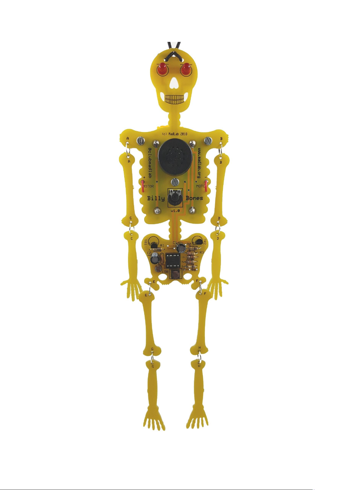
Billy Bones is a seasonal kit in the shape of an articulated skeleton suspended by an elastic cord that laughs
maniacally and ‘dances’ when triggered. It is sensitive to light and can be left in a darkened room for example
where it will be triggered by someone entering the room and turning the light on.
Construction
First separate the circuit board into its individual component parts (main board + smaller ‘backpack’ board + 8
limb bones). They can be snapped at the ‘mouse bites’ by hand or by using pliers. File or sand smooth the
remains of the mouse bites if desired.
Fit and solder the resistors (R1 to R6) to the main circuit board and trim their legs. Identify the resistors by the
coloured stripes on the body.
Next fit the chip socket (IC1) matching the notch in the socket against the notch in the symbol on the board.
Care should be taken when soldering this component to avoid solder bridges between the pins. It is not
recommended that the chip is soldered directly to the board.
Fit and solder the capacitors paying attention to the polarity of the electrolytics C1 and C2 (negative is marked
by the shorter leg and a stripe on the side of the body). The ceramic capacitor (C3) can be fitted either way
around. (Note that the remaining ceramic capacitor is soldered later to the motor.)
Solder the two LEDs to the skull matching the shorter leg (also flat on the rim) to the hole with the line.
Solder the pushbutton (S1), the variable resistor (VR1) and the speaker (SPEAKER).
Solder the light-dependent resistor (LDR) either way around. Be careful not to apply too much heat as it may
damage the component.
Solder the two transistors (TR1 and TR2) matching the shape to the symbol on the board. Note that the two
transistors are different from each other. They can be differentiated by the marking on the side.
Fit the two battery holders to the back of the main board paying attention to their polarity. The spring ends of
the battery holders are negative (–) and should be closer to the skull. Solder the leads to the front of the board.
Don't fit the chip into its socket until you have thoroughly checked your construction. Check that all the
components have been inserted correctly and that there are no dry joints and no solder bridges between pins.
Then match the small notch in the chip to the notch in its socket.
Push the spindle firmly into the variable resistor.
At this point it’s worth checking that the main board is working properly. Fit a pair of 1.5V AAA cells to the
battery holders observing the correct orientation. It is recommended that good quality alkaline cells are used. If
the board is functioning correctly the LEDs should flash twice and the speaker should beep. Remove the cells if
all is well.
The next stage is to assemble the motor backpack and attach it to the main board. Solder the two flexible wires
to the motor terminals along with the remaining capacitor using the sleeving to insulate the capacitor’s legs
(see photo below).

Attach the motor to the backpack board (it’s symmetrical so the side doesn’t matter) and secure it in place with
the cable ties. The spindle of the motor should point towards the broader end of the board (see photo below).
Feed the wires through the support holes on the backpack board then solder the wires to the two holes on the
main board marked MOTOR. There are support holes for the wires on the main board as well.
Insert the AAA cells into the battery holders again. The motor should briefly spin after the LEDs and speaker
have been tested. Remove the cells.
If the motor is working then the backpack can be attached to the main board. Use the three hex spacers and six
bolts to do this.
Fit the articulated limbs together using the jump rings, bending them apart slightly before feeding them
through the holes in the PCBs, then squeezing them shut again. The holes that match are marked with the
same letter. For example ‘A’ on the upper right arm connects to ‘A’ on the right shoulder. Make sure that the
limbs can move freely.
Feed the elastic cord through the holes in the skull and tie the ends together. The elastic is used to suspend
Billy Bones.
The off-centre or eccentric weight attaches to the motor spindle and the self-tapping screws and washers are
used to increases its eccentricity. You can either drill small pilot holes in the side of the weight or use the tip of
a soldering iron to briefly melt into the plastic. Then use a screwdriver to tap the screws into the plastic body
(see photo below). The washers are used to increase the weight. Make sure that the motor can rotate freely
after tightening the screws.
For testing purposes turn VR1 fully anti-clockwise. It will take some experimentation to find the optimal weight,
i.e. the number of screws and washers. If it’s too heavy then the motor won’t be able to rotate reliably, if it’s
too light then the eccentricity won’t be sufficient to make Billy Bones ‘dance’. The amount of weight
determines the character of the dance, how jerky and manic it is. The AAA cells need to be sufficiently ‘fresh’ to
power the motor with the added weight.
How to Use
The LDR reacts to changes in light level and acts as a simple light or motion sensor. The variable resistor sets its
sensitivity (clockwise = less sensitive).
When Billy Bones is triggered by, for example, a room light being switched on it flashes its eyes, plays a manic
laughing sound effect, spins the motor and dances.
The pushbutton sets the mode. Four modes are available indicated by the number of flashes on the LEDs. The
pushbutton steps though the modes in turn:
#1: default sound effect and motion
#2: longer sound effect and motion
#3: sound effect only
#4: motion only


Component List
Resistors
R1 100R (brown, black, brown, gold)
R2, R6 1R (brown, black, gold, gold)
R3 220R (red, red, brown, gold)
R4 1k (brown, black, red, gold)
R5 10k (brown, black, orange, gold)
VR1 47k variable resistor + spindle
Capacitors
C1, C2 100uF electrolytic (blue or black)
C3, C4 100nF ceramic (brown, marked ‘104’)
Semiconductors
TR1 BC547B transistor (black)
TR2 MPSA13 Darlington (black)
IC1 PIC12F1840 microcontroller + 8-pin socket
LED (red) x 2
Miscellaneous
LDR light-dependent resistor
S1 miniature tactile pushbutton
SPEAKER enclosed speaker
motor
off-centre weight (yellow)
battery holder x 2
hex spacer x 3
bolt x 6
cable tie x 3
jump ring x 8
self-tapping screw x 4
washer x 16
elastic cord, 50cm (black)
pre-cut wire x 2
sleeving (grey) x 2
PCB
Design and documentation © MadLab Ltd. 2019
Web: www.madlab.org
Twitter/Instagram: @clubmadlab
Table of contents
Other MadLab Toy manuals


