Mafell BS 18 V Guide

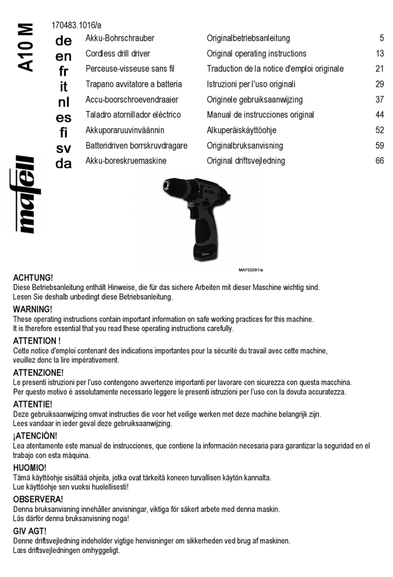
Akku - Bohrschrauber BS / 18 V + BS / 12 V
Betriebsanleitung und Ersatzteilliste
Cordless drill driver BS / 18 V + BS / 12 V
Operating instructions and spare parts list
Perceuse à accu BS / 18 V + BS / 12 V
Notice d´emploi et liste des pièces détachées
Trapano ed avvitatrice ad accumulatore
BS / 18 V + BS / 12 V
Istruzioni d’uso e lista ricambi
Accu-boormachine BS / 18 V + BS / 12 V
Gebruiksaanwijzing en lijst met reservedelen
Taladro atornillador akku BS / 18 V + BS / 12 V
Manual de instrucciones y lista de piezas de recambio
ACHTUNG !
Diese Betriebsanleitung enthält Hinweise, die für das sichere Arbeiten mit dieser Maschine wichtig sind.
Lesen Sie deshalb unbedingt diese Betriebsanleitung sorgfältig durch!
WARNING !
These operating instructions contain important notes on safe working practices with this machine.
It is therefore essential that you read these operating instructions carefully!
AVERTISSEMENT !
Cette notice d´emploi contient des indications importantes pour la sécurité du travail avec cette machine.
Veuillez la lire attentivement !
ATTENZIONE !
Le presenti istruzioni per l’uso contengono avvertenze importanti per lavorare con sicurezza con questa macchina.
Per questo motivo leggete assolutamente le presenti istruzioni per l’uso con la dovuta accuratezza!
ATTENTIE !
Deze gebruiksaanwijzing omvat instructies die voor het veilige werken met deze machine belangrijk zijn.
Leest u vandaar in ieder geval deze gebruiksaanwijzing zorgvuldig door!
¡ATENCIÓN!
Lea atentamente este manual de instrucciones, que contiene la información necesaria para garantizar la
seguridad en el trabajo con esta máquina.
170097.0 10/b6

-2-
Inhaltsverzeichnis
Abbildungen ...................................................... 3
EG Konformitätserklärung................................. 4
1 Erzeugnisangaben ............................................ 5
2 Sicherheitshinweise .......................................... 7
3 Rüsten / Einstellen ............................................8
4 Betrieb............................................................... 9
5 Wartung und Instandhaltung........................... 10
6 Störungsbeseitigung ....................................... 11
7 Sonderzubehör................................................ 11
Ersatzteilliste ............................................ 47 - 48
Garantie .......................................................... 50
Contents
Figures .............................................................. 3
EC Declaration of conformity ............................ 4
1 Product information......................................... 12
2 Safety instructions........................................... 14
3 Setting-up / Adjusting...................................... 15
4 Operation ........................................................ 15
5 Service and maintenance................................ 17
6 Troubleshooting .............................................. 18
7 Optional accessories....................................... 18
Spare parts list .......................................... 47- 48
Warranty.......................................................... 50
Table de matières
Figures .............................................................. 3
Déclaration CE de conformité ........................... 4
1 Données caractéristiques................................ 19
2 Consignes de sécurité..................................... 21
3 Équipement / Installation................................. 22
4 Fonctionnement .............................................. 23
5 Maintenance et nettoyage............................... 24
6 Dérangements................................................. 25
7 Accessoires supplémentaires ......................... 25
Liste des pièces détachées...................... 47 - 48
Garantie .......................................................... 50
Indice
Figure.................................................................3
Dichiarazione di conformità CEE.......................4
1 Informazioni di prodotto ...................................26
2 Avvertenze di sicurezza...................................28
3 Attrezzaggio / Regolazione..............................29
4 Esercizio ..........................................................30
5 Manutenzione e riparazione ............................31
6 Eliminazione dei disturbi..................................32
7 Accessori speciali ............................................32
Lista delle parti di ricambio .......................47 - 48
Garanzia ..........................................................50
Inhoud
Afbeeldingen......................................................3
EG conformiteitsverklaring.................................4
1 Gegevens met betrekking tot het product........33
2 Veiligheidsinstructies .......................................35
3 Voorbereiden / Instellen...................................36
4 Bedrijf...............................................................37
5 Onderhoud en reparatie...................................38
6 Verhelpen van storingen..................................39
7 Extra toebehoren .............................................39
Lijst met reservedelen...............................47 - 48
Garantie...........................................................50
Indice
Figuras...............................................................3
Declaraciòn de conformidad CE........................4
1 Datos del producto...........................................40
2 Instrucciones de seguridad..............................42
3 Preparación / Ajuste ........................................43
4 Funcionamiento ...............................................44
5 Mantenimiento y reparación ............................45
6 Eliminación de fallos técnicos..........................46
7 Accesorios especiales .....................................46
Lista de piezas de recambio.................... 47 - 48
Garantías.........................................................50
D
GB
F
I
NL
E

-3-
Abb. 1 (Fig. 1 ill. 1 afb. 1)

-4-
EG Konformitätserklärung
Wir bescheinigen hiermit, dass der Akku-Bohrschrauber BS/18V + BS/12V, Art.-Nr. 916601,
916610, 916621, 916641 folgenden EU-Richtlinien entspricht:
- EU- aschinenrichtlinie 98/ 7/EG
- EU-Richtlinie elektromagnetische Verträglichkeit 89/ 6/EWG
Bei Konstruktion und Bau wurden folgende Regelwerke angewendet:
EN 60745, EN 55014-1, EN 55014-2, EN 12100 T1, EN 12100 T2, EN 10 7
EC Declaration of conformity
We declare herewith, that the cordless drill driver BS/18V + BS/12V, Ref.-No. 916601, 916610,
916621, 916641 corresponds with the following EC-directives:
- EU-Directive achinery 98/ 7/ECC
- EU-Directive Electromagnetic Compatibility 89/ 6/ECC
Construction has been carried out in accordance with the following regulations:
EN 60745, EN 55014-1, EN 55014-2, EN 12100 T1, EN 12100 T2, EN 10 7
Déclaration CE de conformité
Nous déclarons par la présente, que la perceuse à accu BS/18V + BS/12V, Réference 916601,
916610, 916621, 916641 est conforme aux directives CE applicable comme suit:
- Directive CEE pour les machines 98/ 7/CEE
- Directive CEE sur la conformité électromagnétique 89/ 6/CEE
Lors de la construction les règlements suivants ont été utilisés:
EN 60745, EN 55014-1, EN 55014-2, EN 12100 T1, EN 12100 T2, EN 10 7
Dichiarazione di conformità CEE
Con la presente certifichiamo che la trapano ed avvitatrice ad accumulatore BS/18V + BS/12V,
n° art. 916601, 916610, 916621, 916641 è conforme alle seguenti direttive CE applicabili:
- Direttiva per macchine CE 98/ 7/CE
- Direttiva CE di compatibilità elettromagnetica 89/ 6/CEE
Nella progettazione e la costruzione sono state applicate le seguenti regolamentazioni:
EN 60745, EN 55014-1, EN 55014-2, EN 12100 T1, EN 12100 T2, EN 10 7
EG conformiteitsverklaring
Hiermede bevestigen wij, dat de accu-boormachine BS/18V + BS/12V, art.-nr. 916601, 916610,
916621, 916641 aan de volgende EU-richtlijnen voldoet:
- EU-machinerichtlijn 98/ 7/EG
- EU-richtlijn elektromagnetische verdraagzaamheid 89/ 6/EWG
Bij constructie en bouw werden de folgende voorschriften gehandhaafd:
EN 60745, EN 55014-1, EN 55014-2, EN 12100 T1, EN 12100 T2, EN 10 7
Declaración de conformidad CE
Declaramos por la presente que la taladro atornillador akku BS/18V + BS/12V, referencias
916601, 916610, 916621, 916641 cumple con las siguientes directivas de la UE:
- Directiva máquinas CE 98/ 7/CE
- Directiva CE compatibilidad electromagnética 89/ 6/CEE
La proyección y la construcción de la máquina cumplen con las siguientes normas:
EN 60745, EN 55014-1, EN 55014-2, EN 12100 T1, EN 12100 T2, EN 10 7
afell AG
D – 78727 Oberndorf, den 31.01.2006
. . . . . . . . . . . . . . . . . . . . . . . .
Krauss i. V. Dr. Lauckner

-5-
In dieser Betriebsanleitung finden Sie folgende Warnhinweise und Symbole:
1 Erzeugnisangaben
zu Maschinen mit Art.-Nr. 916 601, 916 610, 916 621, 916 641
1.1 Kennzeichnung der Maschine
Alle zur Identifizierung der Maschine erforderlichen Angaben sind auf dem am Motorgehäuse angebrachten
Leistungsschild vorhanden.
1.2 Technische Daten
Dieses Symbol steht an allen Stellen, wo Sie Hinweise zu Ihrer Sicherheit finden. Bei Nichtbe-
achten können schwerste Verletzungen die Folge sein.
Dieses Symbol kennzeichnet eine möglicherweise schädliche Situation. Wenn sie nicht gemieden
wird, kann das Produkt oder Gegenstände in seiner Umgebung beschädigt werden.
Dieses Symbol kennzeichnet Anwendertipps und andere nützliche Informationen.
³CE-Zeichen zur Dokumentation der Übereinstimmung mit den grundlegenden Sicherheits- und
Gesundheitsanforderungen gemäß Anhang I der Maschinenrichtlinie
³Nur für EU Länder
Werfen Sie Elektrowerkzeuge nicht in den Hausmüll!
Gemäss Europäischer Richtlinie 2002/96/EG über Elektro- und Elektronik- Altgeräte und
Umsetzung in nationales Recht müssen verbrauchte Elektrowerkzeuge getrennt gesammelt
und einer umweltgerechten Wiederverwertung zugeführt werden.
BS / 12 V BS / 18 V
³Bohr-in Stahl 13 mm 13 mm
³Bohr-in Holz 34 mm 38 mm
³Holzschrauben (ohne Vorbohren) 10 mm 12 mm
³Leerlaufdrehzahl
±1. Gang 0 - 420 / min-1 0 - 500 / min-1
±2. Gang 0 - 1300 / min-1 0 - 1600 / min-1
³Drehmoment
±in Weichholz max. *1 22 Nm 32 Nm
±in Stahl max. *2 50 Nm 71 Nm
³Schraubkapazität mit 1 Akkuladung 2,0 Ah 2,4 Ah 2,0 Ah 2,4 Ah
±5 x 40 in Weichholz *3 250 300 350 420
Deutsch
Meßwerte ermittelt entsprechend EN 60 745.
*1 Gerät flexibel eingespannt, Verschraubung gegen Federpaket
*2 Gerät fest eingespannt, Schraube M 12, Schraubweg 12 mm in Stahlplatte
*3 Die angegeben Werte sind Richtwerte. Die tatsächlichen Werte können je nach Material und Schraubengüte davon abweichen.

-6-
1.3 Angaben zur Geräuschemission
Die nach EN 60745 ermittelten Geräuschemissionswerte betragen:
Die Geräuschmessung wurde mit dem serienmäßig mitgelieferten Werkzeug durchgeführt.
Die angegebenen Werte berücksichtigen nicht eine mögliche Serienstreuung und sind nicht geeignet zur Fest-
stellung des Immissionsschalldruckpegels, da dieser in Abhängigkeit von der Einsatzzeit, der jeweiligen Bear-
beitung und den Umgebungseinflüssen schwankt. Der Immissionsschalldruckpegel kann deshalb nur beim
Maschinenanwender im Einzelfall ermittelt werden.
1.4 Angaben zur Vibration
Die typisch bewertete Beschleunigung im Hand-Arm Bereich ist kleiner als 2,5 m/s2.
1.5 Lieferumfang
1.6 Bestimmungsgemäße Verwendung
Jeder weitere, darüber hinausgehende Gebrauch
gilt als nicht bestimmungsgemäß. Für hieraus resul-
tierende Schäden jeder Art haftet der Hersteller
nicht, das Risiko trägt allein der Benutzer.
Ebenso ist diese Maschine nicht geeignet für den
Betrieb im Freien bei Regen oder in explosionsge-
fährdeten Räumen.
Zur bestimmungsgemäßen Verwendung gehört
auch die Einhaltung der von MAFELL vorgeschrie-
benen Betriebs-, Wartungs- und Instandsetzungsbe-
dingungen und die Befolgung der in der Betriebs-
anleitung enthaltenen Sicherheitshinweise.
Der Akku - Bohrschrauber BS / 12 V bzw. BS / 18 V
darf nur von Personen genutzt, gerüstet und gewar-
tet werden, die über 18 Jahre alt, mit der Maschine
vertraut und über die Gefahren unterrichtet sind.
Instandsetzungsarbeiten müssen durch die
MAFELL-Vertragshändler bzw. MAFELL-Kunden-
dienststellen durchgeführt werden.
Die im jeweiligen Verwenderland geltenden Sicher-
heitsbestimmungen, sowie die sonstigen allgemein
³Bohrkapazität mit 1 Akkuladung 2,0 Ah 2,4 Ah 2,0 Ah 2,4 Ah
±3 mm in Stahlblech 1,6 mm 290 350 350 420
±6 mm in Weichholz 20 mm 390 470 470 560
³Spannung Wechselakku 12 V 18 V
³Bohrfutterspannbereich 1,5 - 13 mm 1,5 - 13 mm
³Gewicht mit Wechselakku 2,2 kg 2,7 kg
BS / 12 V BS / 18 V
Typische A-bewertete Schallpegel:
Schalldruckpegel 70 dB (A) 70 dB (A)
Schallleistungpegel >85 dB (A) >85 dB (A)
Der Geräuschepegel beim Arbeiten kann 85 dB (A)
überschreiten.
Akku - Bohrschrauber komplett mit: BS / 12 V BS / 18 V
2 Wechselakkus 18 V 2,0 Ah X
2 Wechselakkus 12 V 2,0 Ah X
1 Zusatzhandgriff X
1 Bitbox X X
1 APS Akku - Power - Station X X
1 Transportkoffer „MAX“ X X
1 Betriebsanleitung BS / 12 V, BS / 18 V X X
1 Betriebsanleitung APS Akku - Power - Station X X
1 Heft „Sicherheitshinweise“ X X
Der Akku - Bohrschrauber BS / 12 V
bzw. BS / 18 V ist universell einsetz-
bar zum Bohren und Schrauben
unabhängig von einem Netzan-
schluss.

-7-
anerkannten arbeitsmedizinischen und sicherheits-
technischen Regeln sind einzuhalten.
Eigenmächtige Veränderungen an der Maschine
schließen eine Haftung des Herstellers für daraus
resultierende Schäden aus.
1.7 Restrisiken
³Berühren des Bohrers beim Bohren.
³Bruch des Bohrers.
³Beeinträchtigung des Gehörs bei länger andau-
ernden Arbeiten ohne Gehörschutz.
³Emission gesundheitsschädlicher Stäube bei
der Bearbeitung von Holz, asbesthaltigen Mate-
rialien und Gestein mit kristalliner Kieselsäure.
2 Sicherheitshinweise
Allgemeine Hinweise:
³Arbeiten Sie nie ohne die für den jeweiligen
Arbeitsgang vorgeschriebenen Schutzvorrich-
tungen und ändern Sie an der Maschine nichts,
was die Sicherheit beeinträchtigen könnte.
³Kinder und Jugendliche dürfen diese Maschine
nicht bedienen. Davon ausgenommen sind
Jugendliche über 16 Jahre unter Aufsicht eines
Fachkundigen zum Zwecke ihrer Ausbildung.
³Berücksichtigen Sie Umgebungseinflüsse. Set-
zen Sie die Maschine nicht dem Regen aus und
vermeiden Sie Arbeiten in feuchter oder nasser
Umgebung sowie in der Nähe von brennbaren
Flüssigkeiten oder Gasen.
³Späne oder Splitter dürfen bei laufender
Maschine nicht entfernt werden.
³Beim Arbeiten in Wand, Decke oder Fußboden
auf elektrische Kabel, Gas- und Wasserleitun-
gen achten.
³Staub der bei der Bearbeitung von asbesthalti-
gen Materialien und Gestein mit kristalliner Kie-
selsäure ensteht, ist gesundheitsschädlich.
Beachten Sie die Unfallverhütungsvorschriften
VBG 119 der Berufsgenossenschaft.
³Vor allen Arbeiten an der Maschine den Wech-
selakku herausnehmen.
³Verbrauchte Wechselakkus nicht ins Feuer oder
in den Hausmüll werfen. MAFELL bietet eine
umweltgerechte Alt - Wechselakku Entsorgung
an, bitte fragen Sie Ihren Fachhändler.
³Wechselakkus nicht zusammen mit Metallge-
genständen aufbewahren (Kurzschlußgefahr).
³MAFELL Wechselakkus nur mit MAFELL Lade-
geräten laden. Keine Akkus aus anderen Syste-
men laden.
³In den Wechselakku - Einschubschacht der
Ladegeräte dürfen keine Metallteile gelangen
(Kurzschlußgefahr).
³
Wechselakkus und Ladegeräte nicht öffnen und nur
in trockenen Räumen lagern. Vor Nässe schützen.
³Bewahren Sie die Maschine an trockenen, ver-
schlossenen Orten außerhalb der Reichweite
von Kindern auf.
Hinweise zur Verwendung persönlicher
Schutzausrüstungen:
³Beim Arbeiten mit der Maschine stets Schutz-
brille tragen. Festes und rutschsicheres Schuh-
werk und Schürze werden empfohlen.
³
Tragen Sie stets eng anliegende Arbeitskleidung
und legen Sie Ringe, Armbänder und Uhren ab.
Bei langen Haaren Haarschutz tragen.
³Der Schalldruckpegel am Ohr kann 85 dB (A)
übersteigen. Tragen Sie deshalb beim Arbeiten
einen Gehörschutz.
Hinweise zum Betrieb:
³Sorgen Sie für einen freien und rutschsicheren
Standplatz mit ausreichender Beleuchtung.
³Kontrollieren Sie vor dem Einschalten, dass das
Werkzeug richtig eingespannt ist.
³Bearbeiten Sie keine Werkstücke, die für die
Leistungsfähigkeit der Maschine zu klein oder
zu großsind.
Auch bei bestimmungsgemäßer
Verwendung können trotz Einhal-
tung aller einschlägigen Sicher-
heitsbestimmungen aufgrund der
durch den Verwendungszweck der
Maschine bedingten Konstruktion
noch Restrisiken auftreten, z. B.:
Maschinen können bei unsachge-
mäßen Gebrauch gefährlich sein.
Beachten Sie deshalb stets die in
diesem Kapitel zusammengefass-
ten Sicherheitshinweise und die
Unfallverhütungsvorschriften Ihrer
Berufsgenossenschaft bzw. die im
jeweiligen Land anzuwendenden
Sicherheitsbestimmungen!
-8-
³
Sichern Sie, wenn immer möglich, das Werkstück
gegen Wegrutschen und Umkippen, z. B. durch
Schraubzwingen.
³Kontrollieren Sie das Werkstück auf Fremdkör-
per.
³Greifen Sie während des Arbeitens nie unter
das Werkstück (Verletzungsgefahr!).
³Vor jeder Benutzung Gerät und Akku überprü-
fen. Werden Schäden festgestellt, Gerät nicht
weiter benutzen. Reparatur nur von einen Fach-
mann durchführen lassen. Gerät nie selbst öff-
nen.
³Vor Einsetzen des Akkus, zum Werkzeugwech-
sel, sowie bei Transport und Aufbewahrung den
Querumschaltschieber stets in Mittelstellung
bringen!
³Vorsicht beim Eindrehen langer Schrauben,
Abrutschgefahr.
³Beim Schrauben im 1. Gang bzw. mit kleiner
Drehzahl arbeiten.
³Passen Sie den Vorschub beim Bohren dem
Bohrer-und der Materialstärke an. Zu großer
Vorschub führt zu Überbelastung des Motors, zu
unsauberen Bohrlöchern und zu einem schnel-
leren Abstumpfen des Bohrers.
³Nie bei laufender Maschine an das Werkzeug
greifen.
Hinweise zur Wartung und Instandhaltung:
³Die regelmäßige Reinigung der Maschine, vor
allem des Bohrfutters, stellt einen wichtigen
Sicherheitsfaktor dar. Vor Beginn dieser Arbei-
ten ist der Akku aus der Maschine zu entneh-
men.
³Es dürfen nur original MAFELL-Ersatz- und
Zubehörteile verwendet werden. Es besteht
sonst kein Garantieanspruch und keine Haftung
des Herstellers.
3 Rüsten / Einstellen
3.1 Akku laden
Die Nennspannung des Akkus muss mit den Anga-
ben auf der Maschine übereinstimmen.
Akku und Ladegerät sind aufeinander abgestimmt.
Zum Laden darf nur ein MAFELL - Schnellladegerät
verwendet werden.
Bei einer neuen Maschine muss zuerst der Akku
aufgeladen werden. Ein neuer Akku bringt erst nach
ca. 5 Lade- und Entladezyklen seine volle Leistung.
Die Inbetriebnahme des Schnellladegerätes sowie die
Beschreibung des Ladevorgangs entnehmen Sie bitte
der beigelegten Anleitung „APS Akku - Power - Station“.
Der Akku ist mit einer Temperaturüberwachung aus-
gestattet, welche Ladung nur im Temperaturbereich
zwischen 5°C und 45°C zuläßt. Dadurch wird eine
hohe Akku Lebensdauer erreicht.
Eine wesentlich verkürzte Betriebszeit je Aufladung
zeigt an, daß der Akku verbraucht ist und ersetzt
werden muss.
Akku nicht auf Heizkörper ablegen oder längere Zeit
starker Sonneneinstrahlung aussetzen, Temperatu-
ren über 50°C schaden. Erwärmten Akku vor dem
Laden abkühlen lassen.
3.2 Werkzeugwechsel
Zum Werkzeugwechsel Schnellspannbohrfutter 1
(Seite 3) durch Drehen der Hülse in Richtung „Auf“
öffnen und Werkzeug einführen. Danach Schnell-
spannbohrfutter durch Drehen der Hülse in Richtung
„Zu“ kräftig spannen (Ratsche muss hörbar sein).
Akku vor Hitze und Feuer schützen:
Explosionsgefahr !
Akku nicht öffnen sowie vor Stoß
schützen. Akku trocken und frostsi-
cher aufbewahren.
Die Kontakte des Akkus bei Aufbe-
wahrung außerhalb des Ladegerä-
tes abdecken. Bei Kurzschluß durch
metallische Überbrückung besteht
Brand- und Explosionsgefahr.
Akku nicht mehrmals hintereinander
schnellladen. Nach kurzzeitigen
Beanspruchungen (z.B. 3 Minuten)
nicht erneut laden.
Hinweise zum Umweltschutz
beachten.
Vor dem Werkzeugwechsel unbe-
dingt Akku aus der Maschine ent-
nehmen (siehe Abschnitt 4.3).

-9-
4 Betrieb
4.1 Erst-Inbetriebnahme
Vor der erstmaligen Inbetriebnahme der Maschine
folgende Hinweise unbedingt beachten:
➤Diese Betriebsanleitung muss allen mit der
Bedienung der Maschine beauftragten Perso-
nen zur Kenntnis gegeben werden, wobei insbe-
sondere auf das Kapitel „Sicherheitshinweise“
aufmerksam zu machen ist.
➤Stellen Sie sicher, dass das Werkzeug korrekt
gespannt ist.
4.2 Akku einsetzen
Querumschaltschieber 2 auf Mitte stellen (Ein-
schaltsperre). Geladenen Akku auf den Griff auf-
schieben bis dieser spürbar einrastet.
Der Akku kann sowohl von vorne als auch von hin-
ten auf den Griff aufgeschoben werden.
4.3 Akku entnehmen
Den Akku durch beidseitigen Druck auf die geriffel-
ten Flächen 3 entriegeln und nach vorne bzw. hinten
vom Griff abziehen.
4.4 Ein- und Ausschalten
Querumschaltschieber 2 auf gewünschte Drehrich-
tung stellen (siehe Abschnitt 4.5).
•Einschalten: Ein-Aus-Schalter 4 drücken.
•
Ausschalten
:
Ein-Aus-Schalter 4 loslassen.
Stufenlose Drehzahlregulierung
Maschine läuft je nach Druck auf den Ein-Aus-
Schalter 4 mit variabler Drehzahl zwischen 0 und
Maximum.
Leichter Druck bewirkt eine kleine Drehzahl und
macht somit einen sanften, kontrollierten Anlauf
möglich.
Die Maschine nicht soweit belasten, dass sie zum
Stillstand kommt.
4.5 Umschalten der Drehrichtung
•Durch Drücken des Querumschaltschiebers 2
nach links wird der Rechtsaluf aktiviert.
•Durch Drücken des Querumschaltschiebers 2
nach rechts wird der Linkslauf aktiviert.
Der Linkslauf ermöglicht z. B. das Lösen von
Schrauben und Muttern.
Bei betätigten Ein - Aus - Schalter 4 ist der Querum-
schaltschieber 2 verriegelt.
4. Gangwahl, mechanisch
Mit dem Schalterschieber 5 können zwei Drehzahl-
bereiche vorgewählt werden:
•Gang I: Niedrige Drehzahl, große Kraft (Schalter-
schieber 5 nach vorne drücken).
•Gang II: Hohe Drehzahl, niedrige Kraft (Schalter-
schieber 5 nach hinten drücken).
4.7 Drehmoment einstellen
Am Schaltring 6 können 20 Einstellungen gewählt
werden.
•Schalterstellung 1: Schwache Einstellung z. B.
für kleine Schrauben, weiche Werkstoffe.
•
•
•
•Schalterstellung 20: Starke Einstellung z. B. für
große Schrauben, harte Werkstoffe.
Bei richtiger Einstellung öffnet die Überrastkupplung,
sobald die Schraube bündig in das Material einge-
dreht bzw. das eingestellte Drehmoment erreicht ist.
Beim Herausdrehen höhere Einstellung wählen,
bzw. auf Bohrersymbol stellen. Die richtige Einstel-
lung ist durch praktischen Versuch zu ermitteln.
Überzeugen Sie sich vor der Benut-
zung vom sicheren Sitz des Akkus
in der Maschine.
Keine Gewalt anwenden.
Drehrichtung nur bei Stillstand der
Maschine umschalten.
Gangwahl nur bei Stillstand der
Maschine umschalten.
Zum Bohren Schaltring 6 ganz nach links
drehen, um das größtmögliche Drehmo-
ment zu erzielen (Bohrersymbol).

-10-
4.8 Bohrfutterwechsel
Das Schnellspannbohrfutter 1 ist gegen Lösen von
der Bohrspindel mit einer Sicherungsschraube gesi-
chert. Schnellspannbohrfutter ganz öffnen und die
Sicherungsschraube vollständig herausschrauben.
Bei festsitzendem Schnellspannbohrfutter 1
Innensechskantschlüssel mit dem kurzen Schaft
voran in Schnellspannbohrfutter einspannen. Durch
einen leichten Schlag auf den langen Schaft des
Schlüssels das Schnellspannbohrfutter lösen und
abschrauben. Die Montage erfolgt sinngemäß,
Schnellspannbohrfutter 1 fest aufschrauben und
Sicherungsschraube eindrehen.
4.9 Montage des Zusatzhandgriffs
(Serienmäßig bei BS / 18 V)
Zusatzhandgriff 9 durch drehen am Handgriff öffnen
und über das Schnellspannbohrfutter 1 und den
Schaltring 6 bis zum Anschlag am Gehäuse schie-
ben. Danach den Zusatzhandgriff in die gewünschte
Arbeitsposition drehen und festspannen.
4.10 Bitgarage
Die Akku - Bohrschrauber BS / 12 V bzw. BS / 18 V
sind an der Vorderseite des Griffs mit einer Bitga-
rage 7 ausgestattet. Zur Entnahme des Bits, Bitga-
rage 7 durch Drücken auf die untere Querrippe öff-
nen. Bit entnehmen und Bitgarage 7 durch
Zuklappen wieder schließen.
4.11 Arbeitshinweise
➤Verwenden Sie nur zum Schraubenknopf pas-
sende Schraubklingen (Bits).
➤Beim Eindrehen größerer, längerer Schrauben
in harte Werkstoffe am besten vorbohren.
➤Beim Bohren in Metall nur einwandfreie
geschärfte HSS-Bohrer (HSS = Hochleistungs-
Schnell-Schnittstahl) verwenden.
5 Wartung und Instandhaltung
5.1 Maschine
Die Maschine muss regelmäßig von abgelagertem
Staub befreit werden. Dabei sollten die Lüftungsöff-
nungen am Motor ausgeblasen werden.
Der Aufbewahrungsort muss trocken und frostfrei sein.
Sollte das Gerät trotz sorgfältiger Herstell- und Prüf-
verfahren einmal ausfallen, ist die Reparatur von
einer autorisierten Kundendienststelle für MAFELL -
Elektrowerkzeuge ausführen zu lassen.
5.2 Austausch der Kohlebürsten
Nach längerer Betriebszeit der Maschine kann ein
Austausch der Kohlebürsten erforderlich sein.
Zum Wechsel der Kohlebürsten, Kohlebürstende-
ckel 8 abschrauben und die verbrauchte Kohle-
bürste aus Ihrer Halterung herausnehmen.
Zum Wechseln des Schnellspann-
bohrfutters 1 Schaltring 6 ganz nach
links drehen (Bohrersymbol) und
Schaltschieber 5 nach vorne drücken
(1. Gang).
Sicherungsschraube hat Linksge-
winde.
Aus Sicherheitsgründen muss beim
Arbeiten mit dem Akku - Bohrschrau-
ber BS / 18 V stets der Zusatzhand-
griff verwendet werden. Er ermöglicht
eine besonders sichere Führung der
Maschine.
Vor allen Arbeiten am Gerät unbe-
dingt Akku aus der Maschine entneh-
men (siehe Abschnitt 4.3).
Die Akku - Bohrschrauber BS / 12 V bzw.
BS / 18 V sind weitgehend wartungsarm
konstruiert. Die eingesetzten Kugellager
sind auf Lebenszeit geschmiert.
Nach längerer Betriebsdauer empfiehlt
MAFELL, die Maschine einer autorisier-
ten MAFELL-Kundendienstwerkstatt zur
Durchsicht zu geben.
Vor dem Austausch der Kohlebürs-
ten unbedingt Akku aus der
Maschine entnehmen (siehe
Abschnitt 4.3).

-11-
Neue Kohlebürste in die Halterung einsetzen und
Kohlebürstendeckel 8 wieder einschrauben. 5.3 Lagerung
Wird die Maschine längere Zeit nicht erwendet, ist
diese sorgfältig zu reinigen (siehe Kapitel 5.1).
Blanke Metallteile mit einem Rostschutzmittel ein-
sprühen.
Maschine nur in trockenen Räumen lagern und or
Witterungseinflüssen schützen.
6 Störungsbeseitigung
Im Folgenden sind einige der häufigsten Störungen und ihre Ursachen aufgeführt. Bei weiteren Störungen wen-
den Sie sich bitte an Ihren Händler oder direkt an den MAFELL-Kundendienst.
7 Sonderzubehör
³Zusatzhangriff (BS / 12 V) Best.-Nr. 094 416
³Wechselakku 12 V, 2,0 Ah (BS / 12 V) Best.-Nr. 094 404
³Wechselakku 18 V, 2,0 Ah (BS / 18 V) Best.-Nr. 094 402
Nur MAFELL-Zubehör und Ersatz-
teile erwenden. Bauteile deren Aus-
tausch nicht beschrieben wurde, bei
einer MAFELL Kundendienststelle
auswechseln lassen.
Die Ermittlung der Ursachen on orliegenden Störungen und deren Beseitigung erfordern stets
erhöhte Aufmerksamkeit und Vorsicht. Vorher unbedingt Akku aus der Maschine entnehmen
(siehe Abschnitt 4.3).
Störung Ursache Beseitigung
Maschine lässt sich nicht einschalten Akku leer Akku laden (siehe Abschnitt 3.1)
Kohlebürsten abgenützt Kohlebürsten austauschen
(siehe Abschnitt 5.2)
Querumschaltschieber in Mittelstellung
(Einschaltsperre) Querumschaltschieber nach links drü-
cken für Rechtslauf
Querumschaltschieber nach rechts
drücken für Linkslauf

-12-
You will find the following warnings and symbols in these operating instructions:
1 Product information
for machines with Art.-No. 916 601, 916 610, 916 621, 916 641
1.1 Machine identification
All data required for identification of the machine are stated on the rating plate which is attached to the motor
casing.
1.2 Technical data
This symbol indicates where you will find notes for your safety. If disregarded, this may result in
very serious injuries.
This symbol indicates a potentially hazardous situation. If it is disregarded, the product or objects
in its vicinity may be damaged.
This symbol indicates tips for the user and other useful information.
³CE-mark to declare conformity with the essential health and safety requirements according to
Annex I of the Machinery Directive
³Only for EU countries
Do not dispose of electric tools together with household waste material!
In observance of European Directive 2002/96/EC on waste electrical and electronic equipment
and its implementation in accordance with national law, electric tools that have reached the
end of their life must be collected separately and returned to an environmentally compatible
recycling facility.
BS / 12 V BS / 18 V
³Drilling in steel 13 mm (1/2 in.) 13 mm (1/2 in.)
³Drilling in wood 34 mm (1 21/64 in.) 38 mm (1 1/2 in.)
³Wooden screws (without predrilling) 10 mm (25/64 in.) 12 mm (15/32 in.)
³Speed at no load
±1st gear 0 - 420 / rpm 0 - 500 / rpm
±2nd gear 0 - 1300 / rpm 0 - 1600 / rpm
³Torque
±in softwood max. *1 22 Nm 32 Nm
±in steel max. *2 50 Nm 71 Nm
³Screw capacity with 1 battery load 2.0 Ah 2.4 Ah 2.0 Ah 2.4 Ah
±5 x 40 in softwood *3 250 300 350 420
English
Measuring values determined in accordance with EN 60 745.
*1 Device flexibly clamped, screwed against spring assembly
*2 Device firmly clamped, screw M 12, screw path 12 mm in steel plate
*3 The indicated values are guide values. The actual values may deviate in dependence of the material and the screw quality.

-13-
1.3 Noise emission
The noise emission values determined according to EN 60745 are as follows:
The noise measurement was carried out by means of the respective tool which is part of the standard scope of
delivery.
The specified values do not take a possible series scattering into account and are not suitable for determining
the immission sound pressure level as the latter varies in dependence of the respective operating time, the type
of operation and the environmental influences. The immission sound pressure level can therefore only be speci-
fied for individual cases at the machine user.
1.4 Vibration
The typical rated acceleration in the hand-arm area is smaller than 2.5 m/s2.
1.5 Delivery specification
1.6 Use according to intended purpose
Any other use beyond this scope is considered as
failure to comply with the intended purpose. The
manufacturer is not liable for any damage caused as
a result of this; the risk is borne solely by the user.
Furthermore, the machine is not suitable for opera-
tion outdoors in the rain or in areas subject to explo-
sion hazards.
Use according to the intended purpose also includes
compliance with the operating, maintenance and
repair conditions specified by MAFELL, and adher-
ence of the safety instructions contained in the oper-
ating manual.
The cordless drill drivers BS / 12 V and BS / 18 V
must be operated, tooled and maintained only by
persons above the age of 18 familiar with the
machine and instructed as to the risks. Repair work
must be carried out by authorized MAFELL dealers
or MAFELL customer service stations.
³Drilling capacity with 1 battery load 2.0 Ah 2.4 Ah 2.0 Ah 2.4 Ah
±3 mm in sheet steel 1.6 mm 290 350 350 420
±6 mm in softwood 20 mm 390 470 470 560
³Voltage interchangeable battery 12 V 18 V
³Chuck clamping range 1.5 - 13 mm (1/16 - 1/2 in.) 1.5 - 13 mm (1/16 in - 1/2 in.)
³Weight incl. interchangeable battery 2.2 kg (4.84 lbs) 2.7 kg (5.95 lbs)
BS / 12 V BS / 18 V
Typical A-rated sound levels:
Sound pressure level 70 dB (A) 70 dB (A)
Sound power level >85 dB (A) >85 dB (A)
During operation, the noise level may exceed 85 dB (A).
Cordless drill driver complete with: BS / 12 V BS / 18 V
2 interchangeable batteries 18 V 2.0 Ah X
2 interchangeable batteries 12 V 2.0 Ah X
1 additional handle X
1 bit box X X
1 APS Akku - Power - Station X X
1 "MAX" transport case X X
1 set of operating instructions for BS / 12 V, BS / 18 V X X
1 set of operating instructions for the APS
Akku - Power - Station
XX
1 folder "Safety instructions" X X
The cordless drill drivers BS / 12 V
and BS / 18 V are universally appli-
cable for drilling and screwing oper-
ations without the need for a supply
connection.

-14-
The relevant accident prevention regulations and
other generally recognized industrial, medical and
technical safety rules must be complied with.
Unauthorized modifications to the machine preclude
the liability of the manufacturer for any resultant
damage.
1.7 Residual risks
³Touching the bit during drilling operations.
³Bit breakage.
³Hearing can be impaired when working for long
periods without ear protectors.
³Emission of hazardous dust when working with
wood, asbestos-containing materials and stones
with crystalline sillicic acid.
2 Safety instructions
General instructions:
³Never work without the protective equipment
prescribed for the relevant operation and do not
make any modifications to the machine that
could undermine safety.
³Children and young persons must not operate
this machine. This rule does not apply to young
persons over the age of 16 years receiving train-
ing and being supervised by an expert.
³Always be aware of environmental influences.
Do not allow the machine to be exposed to the
rain and do not use the machine in a damp or
wet environment, or in the vicinity of inflamma-
ble liquids or gases.
³Chips or splinters must not be removed during
machine operation.
³Observe electrical wires, gas or water lines
when carrying out works on the wall, ceiling or
floor.
³Dust arising from the machining of asbestos-
containing materials and stones with crystalline
sillicic acid is hazardous to health. Adhere to the
accident prevention regulations VBG 119 of the
relevant liability insurance association.
³Prior to carrying out any works at the machine,
remove the interchangeable battery.
³Do not put used-up interchangeable batteries
into fire or domestic waste. MAFELL offers an
environmentally-friendly disposal of used-up
interchangeable batteries. Please ask your
dealer.
³Do not store interchangeable batteries together
with metal objects (risk of short-circuits).
³Charge MAFELL interchangeable batteries only
by means of MAFELL chargers. Do not charge
any batteries from other systems.
³No metal objects must enter the interchangea-
ble battery slide-in opening of the chargers (risk
of short-circuits).
³
Interchangeable batteries and chargers must not be
opened and only be stored in dry rooms. Protect
them against humidity.
³Store the machine in the dry under lock and key
and out of the reach of children.
Instructions on the use of personal safety
equipment:
³Always wear protective goggles when working
with the machine. As well as sturdy and anti-slip
footwear and the use of an apron are recom-
mendable.
³
Always wear close-fitting industrial clothing and
remove rings, bracelets and watches. With long
hair, a respective hair protection is required.
³The sound pressure level at the workplace may
exceed 85 dB (A). Users should therefore wear
ear protectors.
Instructions on operation:
³Provide an uncluttered, anti-slip location with
adequate illumination.
³Prior to switching on the machine, make sure
that the tool has been properly clamped.
Residual risks may also arise owing
to the design of the machine relat-
ing to its intended purpose even if
the machine is used properly and in
compliance with all relevant safety
regulations; e.g.:
If used incorrectly, machines can be
dangerous. For this reason, always
comply with the safety instructions
summarized in this chapter, the
accident prevention regulations of
the relevant liability insurance asso-
ciations or equivalent, and the
safety regulations applicable in the
country concerned!

-15-
³Never work with pieces which are too big or too
small for the machine´s capacity.
³
Whenever possible, secure the workpiece against
slipping and tipping over (e.g. with screw clamps).
³Examine the workpiece for foreign objects.
³Keep hands well away from the area under the
workpiece when drilling (risk of injury!).
³Examine both the device and the battery prior to
use. In case of any damage, do not use the
device. Repairs must be carried out by experts
only. Never open the device yourself.
³Prior to inserting the battery, for tool replace-
ment as well as for transport and storage, the
crosswise changeover slider must always be set
to the centre position!
³Be careful when screwing in long screws. Risk
of sliding down!
³For screwing operations, use the 1st gear and
work at low speed.
³
For drilling operations, match the feed rate to the
drill
and material thickness. Excessive feed
rates overload the motor, lead to poorly executed
drill holes and blunt the drill prematurely.
³Never touch the tool during machine operation.
Instructions on service and maintenance:
³Regular cleaning of the machine, especially the
chuck, is an important safety factor. Before
beginning this task, remove the battery from the
machine.
³Only original MAFELL spare parts and accesso-
ries must be used. Otherwise the manufacturer
does not offer any warranty and does not accept
any liability.
3 Setting-up / Adjusting
3.1 Charging the battery
The nominal voltage of the rechargeable battery
must conform to the specifications on the machine.
The battery and the charger are matched to each
other. For charging purposes, only a MAFELL rapid
charging device may be used.
If a new machine is used, the battery must be
charged first. A new battery only offers full power
after approx. 5 charging and discharging cycles.
For commissioning of the rapid charging device and for
a description of the charging process, please refer to
the enclosed "APS - Akku - Power - Station" manual.
The rechargeable battery has been equipped with a
temperature monitor which only allows for charging
in the temperature range between 5°C and 45°C.
This ensures a long service life of the battery.
If the operating times after the respective charging
processes considerably decrease, the battery is
used-up and must be replaced.
Do not put down the battery on a heater or expose it to
strong solar radiation over longer periods of time. Tem-
peratures exceeding 50°C are harmful. Cool down the
warmed battery prior to the charging process.
3.2 Tool replacement
For tool replacement, open the quick-action chuck 1
(page 3) by turning the sleeve in "Open" direction
and insert the tool. Then, firmly clamp the quick-
action chuck by turning the sleeve in "Close" direc-
tion (the ratchet must be audible).
Protect the battery against heat and
fire:
Risk of explosion !
Do not open the battery and protect
it against shocks. Store the battery
at a dry and frost-proof place.
Cover the contacts if the battery is
stored outside the charger. Short-
circuits due to metallic jumpering
bear the risk of fire and explosion.
Do not carry out rapid charging
processes consecutively. Do not re-
charge the battery after short opera-
tions (e.g. 3 minutes).
Observe the instructions on envi-
ronmental protection.
Prior to any tool replacement, it is
imperative to remove the battery from
the machine (refer to section 4.3).

-16-
4 Operation
4.1 Initial operation
Before using the machine for the first time, it is impe-
rative to observe the following notes:
³Personnel entrusted to work with the machine
must have read the operating instructions. Main
importance has to be attached to the chapter
„Safety instructions“.
³
Make sure that the tool has been properly clamped.
4.2 Inserting the battery
Set the crosswise changeover switch 2 to the centre
position (starting lock-off). Slide the charged battery
onto the handle until it noticeably locks into place.
The battery may be slid onto the handle either from
the front or back.
4.3 Removing the battery
Unlock the battery by exerting bilateral pressure on
the rippled surfaces 3 and slide it off the handle to
the front or back.
4.4 Switching on and off
Set the crosswise changeover switch 2 to the
desired direction of rotation (refer to section 4.5).
•Switching on: Press ON-OFF switch 4.
•
Switching off
:
Release ON-OFF switch 4.
Continuous speed adjustment
Depending on the pressure exerted on the ON-OFF
switch 4, the machine operates at a variable speed
between 0 and the maximum value.
Little pressure means small speed and therefore
enables a soft and controlled start-up.
Do not load the machine to such an extent that it
comes to a halt.
4.5 Changing over the direction of rotation
• By pressing the crosswise changeover slider 2 to
the left, clockwise rotation is activated.
• By pressing the crosswise changeover slider 2 to
the right, anti-clockwise rotation is activated.
Anti-clockwise rotation facilitates, e.g., the loosening
of screws and nuts.
When operating the ON-OFF switch 4, the crosswise
changeover slider 2 is locked.
4.6 Gear selection, mechanical
By means of the switch slider 5, two speed ranges
can be preselected:
•Gear I: Low speed, high power (press switch
slider 5 forwards).
•Gear II: High speed, low power (press switch
slider 5 backwards).
4.7 Adjusting the torque
At selector ring 6, 20 selections can be made.
•Switch position 1: Weak setting, e.g. for small
screws, soft materials.
•
•
•
•Switch position 20: Hard setting, e.g. for large
screws, hard materials.
With a correct setting, the overlatching clutch opens
as soon as the screw has been embedded in the
material or the set torque has been achieved. For
screwing out the screw, select a higher setting or set
the switch to the drill symbol. The correct setting
must be determined by means of a practical test.
Ensure a tight fit of the battery in the
machine prior to use.
Do not use force.
Only change the direction of rotation
when the machine has come to a
halt.
Only change the gear when the
machine has come to a halt.
For drilling operations, turn the selector
ring 6 completely to the left to attain the
maximum torque (drill symbol).

-17-
4.8 Chuck replacement
The quick-action chuck 1 is secured with a lock
screw to prevent it from disengagement from the drill
spindle. Completely open the quick-action chuck
and screw out the lock screw.
With a fixed quick-action chuck 1, clamp the Allen key
with the short shaft ahead into the quick-action chuck.
Loosen the quick-action chuck by a soft stroke onto
the long key shaft and unscrew it. The mounting is
carried out in the reverse order, firmly screw on quick-
action chuck 1 and screw in the lock screw.
4.9 Mounting of the additional handle
(included in the standard scope of delivery
BS / 18 V)
Open the additional handle 9 by turning the handle
and slide it over the quick-action chuck 1 and the
selector ring 6 to the limit stop at the casing. Subse-
quently, turn the additional handle to the desired
operating position and fix it.
4.10 Bit carrier
The cordless drill drivers BS / 12 V and BS / 18 V have
been equipped with a bit carrier 7 at the front side of
the handle. To remove the bits, open the bit carrier 7
by applying pressure onto the lower transverse rib.
Take out a bit and close the bit carrier 7 with a snap.
4.11 Operating instructions
³
Only use bits which are suitable for the screw head.
³Predrill a hole for screwing larger, longer screws
into hard materials.
³
For drilling metal, only use properly sharpened
SHSS-tipped drills (SHSS = super-high speed steel).
5 Service and maintenance
5.1 Machine
The machine must be regularly cleaned of dust, at
the same time blowing out the motor ventilation
apertures.
The depository must be dry and chill-free.
If, despite careful manufacturing and test proce-
dures, the device fails, the respective repair works
must be carried out by an authorized MAFELL cus-
tomer service station for electrical tools.
5.2 Replacement of carbon brushes
After long operating times of the machine, a replace-
ment of the carbon brushes may become necessary.
To replace the carbon brushes screw off the carbon
brush cover 8 and take the used-up carbon brush
out of its holder.
Insert a new carbon brush into the holder and screw
in the carbon brush cover 8.
To replace the quick-action chuck 1,
turn selector ring 6 completely to the
left (drill symbol) and press the
switch slider 5 forwards (1st gear).
The lock screw is equipped with a
left-hand thread.
For safety reasons, the additional
handle must always be used when
working with the cordless drill driver
BS / 18 V. It allows for a particular
safe machine guidance.
Prior to carrying out any works at the
device, it is imperative to remove the
battery from the machine (refer to
section 4.3).
The cordless drill drivers BS / 12 V and
BS / 18 V are designed with a low main-
tenance requirement. The ball bearings
used are greased for life.
After a prolonged period of operation,
users are recommended to have the
machine checked by an authorized
MAFELL customer service shop.
Prior to replacing the carbon
brushes, it is imperative to remove
the battery from the machine (refer to
section 4.3).
Only use MAFELL accessories and
spare parts. Components whose
replacement has not been described
here are to be replaced at a MAFELL
customer service station.

-18-
5.3 Storage
If the machine is not in use over a longer period of
time, it must be carefully cleaned (refer to chapter
5.1). Spray plain metal parts with an antirust agent.
Only store the machine in dry rooms and protect it
against atmospheric influences
6 Troubleshooting
Some of the most frequent defects and their causes are listed in the following chart. In case of other defects,
contact your dealer or the MAFELL customer service.
7 Optional accessories
³Additional handle (BS / 12 V) Ref. No. 094 416
³Interchangeable batterie 12 V 2.0 Ah (BS / 12 V) Ref. No. 094 404
³Interchangeable batterie 18 V 2.0 Ah (BS / 18 V) Ref. No. 094 402
The determination of the causes of existing defects and their eliminations always require
increased attention and caution. It is imperative to remove the battery from the machine before
carrying out any troubleshooting (refer to section 4.3).
Defect Cause Elimination
Machine cannot be switched on Empty battery Charge battery (refer to section 3.1)
Carbon brushes are used up Replace the carbon brushes
(refer to section 5.2)
Crosswise changeover slider in centre
position (starting lock-off)
Press the crosswise changeover slider
to the left for clockwise rotation
Press the crosswise changeover slider
to the right for anti-clockwise rotation

-19-
Vous trouverez dans la présente notice les symboles et mises en garde suivants :
1 Données caractéristiques
pour les machines ayant l'art. n° 916 601, 916 610, 916 621, 916 641
1.1 Identification de la machine
Toutes les indications pour l'identification de la machine sont présentes sur la plaque signalétique fixée sur le
carter du moteur.
1.2 Caractéristiques techniques
Ce symbole figure partout où vous trouverez des consignes concernant votre sécurité. Leur non
respect peut entraîner des blessures très graves.
Ce symbole signale une situation potentiellement dommageable. Si elle n'est pas évitée, le pro-
duit ou les objets situés à proximité peuvent être endommagés.
Ce symbole signale des astuces d'utilisation et autres informations utiles.
³Marque CE pour documenter la conformité avec les exigences fondamentales de sécurité et
de santé suivant appendice I de la directive pour les machines
³Pour les pays européens uniquement
Ne pas jeter les appareils électriques dans les ordures ménagères !
Conformément à la directive européenne 2002/96/EG relative aux déchets d'équipements
électriques ou électroniques (DEEE), et à sa transposition dans la législation nationale, les
appareils électriques doivent être collectés à part et être soumis à un recyclage respectueux
de I'environnement.
BS / 12 V BS / 18 V
³de perçage dans l'acier 13 mm 13 mm
³de perçage dans le bois 34 mm 38 mm
³Vis à bois (sans avant-trou) 10 mm 12 mm
³Vitesse de rotation à vide
±1ère vitesse 0 - 420 min-1 0 - 500 min-1
±2ème vitesse 0 - 1300 min-1 0 - 1600 min-1
³Couple de rotation
±dans du bois doux, maxi *1 22 Nm 32 Nm
±dans de l'acier, maxi *2 50 Nm 71 Nm
³Capacité de vissage avec 1 charge d'accu 2,0 Ah 2,4 Ah 2,0 Ah 2,4 Ah
±5 x 40 dans du bois doux *3 250 300 350 420
Français
Valeurs mesurées conformément à EN 60 745.
*1 Appareil bridé de façon flexible, vissage contre paquet de ressorts
*2 Appareil bridé de façon fixe, vis M 12, course de vis de 12 mm dans plaque d'acier
*3 Les valeurs indiquées sont des valeurs approximatives. Les valeurs réelles peuvent diverger suivant le matériau et la qualité des vis.

-20-
1.3 Niveau sonore
Valeurs d'émission sonore déterminées sui ant la norme EN 60745 :
La mesure d'émission sonore a été effectuée a ec l'outil de série li ré.
Les aleurs données ici ne tiennent pas compte d'une possible dispersion et ne peu ent pas être prises en
compte pour la détermination du ni eau d'émission de pression acoustique, car ce dernier arie en fonction de la
durée d'utilisation, du type de tra ail et des conditions en ironnantes. Le ni eau d'émission de pression acou-
stique ne peut donc être établi que chez l'utilisateur de la machine et cas par cas.
1.4 Vibration
La ibration typique main-bras ne dépasse pas 2,5 m/s2.
1.5 Équipement standard
1.6 Utilisation conforme
Toute utilisation en dehors de ces limites n'est pas
considérée comme autorisée et le constructeur n'est
pas tenu responsable des dommages de tous ordres
qui pourraient en résulter ; seul l'utilisateur en
endosse le risque.
Cette machine n'est pas utilisable en plein air et par
temps de pluie, ni dans des enceintes où règne un
danger d'explosion.
La prise en compte des consignes d'utilisation,
d'entretien et de maintenance prescrites par
MAFELL, de même que les consignes de sécurité
figurant dans la notice d'emploi sont à rattacher à
l'utilisation conforme.
La perceuse à accu BS / 12 V ou BS / 18 V ne doit
être utilisée, équipée et entretenue que pas des per-
sonnes âgées de plus de 18 ans, familiarisées a ec
ces opérations et a erties des dangers. Les tra aux
de réparation doi ent être exécutés par les déposi-
taires agréés MAFELL ou par une station ser ice
après- ente MAFELL.
Les consignes officielles de pré ention des acci-
dents de même que toutes les prescriptions généra-
les de la médecine du tra ail et des règles générales
de sécurité sont à prendre en considération.
³Capacité de perçage a ec 1 charge d'accu 2,0 Ah 2,4 Ah 2,0 Ah 2,4 Ah
±3 mm dans tôle d'acier de 1,6 mm 290 350 350 420
±6 mm dans bois doux de 20 mm 390 470 470 560
³Tension de l'accu de rechange 12 V 18 V
³Plage de serrage du mandrin de perceuse 1,5 - 13 mm 1,5 - 13 mm
³Poids a ec accu de rechange 2,2 kg 2,7 kg
BS / 12 V BS / 18 V
Ni eau sonore typique rele é sui ant :
Ni eau de pression acoustique 70 dB (A) 70 dB (A)
Ni eau de puissance acoustique >85 dB (A) >85 dB (A)
Le ni eau sonore pendant le tra ail peut dépasser 85 dB (A).
Perceuse à accu complète a ec : BS / 12 V BS / 18 V
2 accus de rechange 18 V 2,0 Ah X
2 accus de rechange 12 V 2,0 Ah X
1 poignée supplémentaire X
1 boîte de mèches X X
1 APS Akku - Power - Station X X
1 coffret transportable «MAX» X X
1 notice d'instructions BS / 12 V, BS / 18 V X X
1 notice d'instructions APS Akku - Power - Station X X
1 carnet «Consignes de sécurité» X X
La perceuse à accu BS / 12 V ou
BS / 18 V est utilisable de façon uni-
erselle pour le perçage et le is-
sage, indépendamment d'une ali-
mentation sur secteur.
This manual suits for next models
1
Table of contents
Languages:
Other Mafell Drill manuals

Mafell
Mafell A18 M bl User manual

Mafell
Mafell BST 650S Quick guide

Mafell
Mafell A10 M User manual

Mafell
Mafell ZB 100 ES User manual

Mafell
Mafell A18 M bl User manual

Mafell
Mafell A12 Quick guide

Mafell
Mafell A18 Quick guide

Mafell
Mafell HB 2 E Guide

Mafell
Mafell ZB 400E User manual

Mafell
Mafell A18 M bl Quick guide