Mafell ZB 400E User manual

070923.0515/m
(+ 070911)
Zimmerei-Bohrmaschine ZB 400 / 600 E
Originalbetriebsanleitung
Carpentry Drilling Machine ZB 400 / 600 E
Original operating instructions
Perceuse pour charpente ZB 400 / 600 E
Traduction de la notice d'emploi originale
Trapano per carpenteria ZB 400 / 600 E
Istruzioni per l'uso originali
Timmermans-Boormachine ZB 400 / 600 E
Originele gebruiksaanwijzing
Taladradora de carpintero ZB 400 / 600 E
Manual de instrucciones original
ACHTUNG !
Diese Betriebsanleitung enthält Hinweise, die für das sichere Arbeiten mit dieser Maschine wichtig sind.
Lesen Sie deshalb unbedingt diese Betriebsanleitung sorgfältig durch!
WARNING !
These operating instructions contain important notes on safe working practices with this machine.
It is therefore essential that you read these operating instructions carefully!
AVERTISSEMENT !
Cette notice d´emploi contient des indications importantes pour la sécurité du travail avec cette machine.
Veuillez la lire attentivement !
ATTENZIONE !
Le presenti istruzioni per l’uso contengono avvertenze importanti per lavorare con sicurezza con questa macchina.
Per questo motivo leggete assolutamente le presenti istruzioni per l’uso con la dovuta accuratezza!
ATTENTIE !
Deze gebruiksaanwijzing omvat instructies die voor het veilige werken met deze machine belangrijk zijn.
Leest u vandaar in ieder geval deze gebruiksaanwijzing zorgvuldig door!
¡ATENCIÓN!
Lea atentamente este manual de instrucciones, que contiene la información necesaria para garantizar la
seguridad en el trabajo con esta máquina.

-2-
Inhaltsverzeichnis
Abbildungen...................................................... 3
EG Konformitätserklärung................................. 4
1 Erzeugnisangaben............................................ 5
2 Sicherheitshinweise .......................................... 7
3 Rüsten / Einstellen............................................ 8
4 Betrieb............................................................... 8
5 Wartung und Instandhaltung............................. 9
6 Störungsbeseitigung ....................................... 10
7 Sonderzubehör................................................10
8 Explosionszeichnung und Ersatzteilliste.........10
Garantie..........................................................46
Contents
Figures.............................................................. 3
EC Declaration of conformity ............................ 4
1 Product information.........................................11
2 Safety instructions...........................................13
3 Setting up / Adjusting...................................... 14
4 Operation........................................................14
5 Service and maintenance................................ 15
6 Troubleshooting..............................................16
7 Optional accessories....................................... 16
8 Exploded drawing and spare parts list............ 16
Warranty..........................................................46
Table de matières
Figures.............................................................. 3
Déclaration CE de conformité........................... 4
1 Données caractéristiques................................ 17
2 Consignes de sécurité..................................... 19
3 Equipement / Installation................................. 20
4 Fonctionnement ..............................................20
5 Maintenance et nettoyage............................... 21
6 Dérangements.................................................22
7 Accessoire supplémentaire............................. 22
8 Schéma éclaté et liste de pièces de rechange22
Garantie..........................................................46
Indice
Figure.................................................................3
Dichiarazione di conformità CEE.......................4
1 Informazioni di prodotto...................................23
2 Avvertenze di sicurezza...................................25
3 Attrezzaggio / Regolazione..............................26
4 Esercizio..........................................................27
5 Manutenzione e riparazione............................27
6 Eliminazione dei disturbi..................................28
7 Accessori speciali............................................28
8 Disegno esploso e distinta dei ricambi ............28
Garanzia..........................................................46
Inhoud
Afbeeldingen......................................................3
EG conformiteitsverklaring.................................4
1 Gegevens van de fabrikant..............................29
2 Veiligheidsinstructies.......................................31
3 Voorbereiden / Instellen...................................32
4 Bedrijf...............................................................32
5 Onderhoud en reparatie...................................33
6 Verhelpen van storingen..................................34
7 Extra toebehoren.............................................34
8 Explosietekening en onderdelenlijst ................34
Garantie...........................................................46
Indice
Figuras...............................................................3
Declaraciòn de conformidad CE........................4
1 Datos del producto...........................................35
2 Instrucciones de seguridad..............................37
3 Preparación / Ajuste ........................................38
4 Funcionamiento...............................................39
5 Mantenimiento y reparación ............................39
6 Eliminación de fallos técnicos..........................40
7 Accesorios especiales.....................................40
8 Dibujo de explosión y lista de piezas de recambio... 40
Garantía...........................................................46

-3-
Abb. 1 (Fig. 1 ill. 1 afb. 1)
Abb. 3 (Fig. 3 ill. 3 afb. 3)
Abb. 5 (Fig. 5 ill. 5 afb. 5)
Abb. 4 (Fig. 4 ill. 4 afb. 4)
Abb. 2 (Fig. 2 ill. 2 afb. 2)
Drehzahleinstellung
Cutting speed adjustment
Réglage de la vitesse de coupe
Regolazione del numero di giri
Instelling van het toerental
Ajuste de la velocidad
Abb. 7 (Fig. 7 ill. 7 afb. 7)Abb. 6 (Fig. 6 ill. 6 afb. 6)


-5-
In dieser Betriebsanleitung finden Sie folgende Warnhinweise und Symbole:
1 Erzeugnisangaben
1.1 Angaben zum Hersteller
MAFELL AG
Postfach 1180, D-78720 Oberndorf/Neckar
Telefon (07423) 812-0, Fax (07423) 812-218
1.2 Kennzeichnung der Maschine
Alle zur Identifizierung der Maschine erforderlichen Angaben sind auf dem am Motorgehäuse angebrachten
Leistungsschild vorhanden.
1.3 Technische Daten
Dieses Symbol steht an allen Stellen, wo Sie Hinweise zu Ihrer Sicherheit finden. Bei Nichtbe-
achten können schwerste Verletzungen die Folge sein.
Dieses Symbol kennzeichnet eine möglicherweise schädliche Situation. Wenn sie nicht gemieden
wird, kann das Produkt oder Gegenstände in seiner Umgebung beschädigt werden.
Dieses Symbol kennzeichnet Anwendertipps und andere nützliche Informationen.
zu Maschinen mit Art.-Nr. 922 901, 922 905 oder 922 920 (ZB 400 E)
923 301 oder 923 320 (ZB 600 E)
Schutzklasse II
CE-Zeichen zur Dokumentation der Übereinstimmung mit den grundlegenden Sicherheits- und
Gesundheitsanforderungen gemäß Anhang I der Maschinenrichtlinie
Nur für EU Länder
Werfen Sie Elektrowerkzeuge nicht in den Hausmüll !
Gemäss Europäischer Richtlinie 2002/96/EG über Elektro- und Elektronik- Altgeräte und
Umsetzung in nationales Recht müssen verbrauchte Elektrowerkzeuge getrennt gesammelt
und einer umweltgerechten Wiederverwertung zugeführt werden.
Deutsch
Bohrtiefe mit Bohrerführung ZB 400 E 350 mm
ZB 600 E 475 mm
Bohrtiefe ohne Bohrerführung ZB 400 E 380 mm
ZB 600 E 505 mm
Schwenkbar bis 45°
Bohrer - ZB 400 E 10 – 30 mm
ZB 600 E 12 – 30 mm
Bohrerlänge ZB 400 E 650 mm
ZB 600 E 820 mm
Spannhals 63 mm

-6-
Universalmotor funk- und fernsehentstört 230 V~, 50 Hz
Aufnahmeleistung Dauerbetrieb 1200 W
Abgabeleistung 760 W
1.4 Angaben zur Geräuschemission
Die nach EN 60745-1 und 60745-2-1 ermittelten Geräuschemissionswerte betragen:
Die Geräuschmessung wurde mit dem serienmäßig mitgelieferten Bohrer durchgeführt.
Die angegebenen Werte berücksichtigen nicht eine mögliche Serienstreuung und sind nicht geeignet zur Fest-
stellung des Immissionsschalldruckpegels, da dieser in Abhängigkeit von der Einsatzzeit, der jeweiligen Bear-
beitung und den Umgebungseinflüssen schwankt. Der Immissionsschalldruckpegel kann deshalb nur beim
Maschinenanwender im Einzelfall ermittelt werden.
1.5 Angaben zur Vibration
Die typische Hand-Arm-Schwingung ist kleiner als 2,5 m/s2.
1.6 Lieferumfang
Zimmerei-Bohrmaschine ZB 400 E oder ZB 600 E komplett mit:
1 Bohrgestell kpl.
1 Bohrerführung
1 Holzbohrer 18 mm
1 Adapter MK2, Art.-Nr. 039 139
1 Betriebsanleitung
1 Heft «Sicherheitshinweise»
1.7 Bestimmungsgemäße Verwendung
Die MAFELL Zimmerei-Bohrmaschine ZB 400 E /
600 E ist ausschließlich zum Bohren von Massivholz
unter Verwendung von Holzbohrern vorgesehen.
Die Länge der Holzbohrer muss bei der ZB 400 E
650 mm und bei der ZB 600 E 820 mm betragen.
Ein Bohrer - 10 bis 30 mm wird empfohlen.
In Verbindung mit dem Sonderbohrgestell 039 160
(Sonderzubehör) ist die Zimmerei-Bohrmaschine
ZB 400 E / 600 E zum Senken mit Dübel-, Kopfsen-
kern und Ringdübelwerkzeugen vorgesehen, die als
Sonderzubehör von der Fa. MAFELL angeboten
werden.
Jeder weitere, darüber hinausgehende Gebrauch
gilt als nicht bestimmungsgemäß. Für hieraus resul-
tierende Schäden jeder Art haftet der Hersteller
nicht; das Risiko trägt allein der Benutzer.
Ebenso ist diese Maschine nicht geeignet für den
Betrieb im Freien bei Regen oder in explosionsge-
fährdeten Räumen.
Zur bestimmungsgemäßen Verwendung gehört
auch die Einhaltung der von MAFELL vorgeschrie-
benen Betriebs-, Wartungs- und Instandsetzungsbe-
dingungen und die Befolgung der in der Betriebs-
anleitung enthaltenen Sicherheitshinweise.
Bohrer-Leerlaufdrehzahl 340 – 1450 min-1
2-stufiges mechanisches Getriebe
Elektronische Drehzahlregelung stabilisiert unter Last
Rechts – Linkslauf
Gewicht ohne Netzkabel - mit Gestell ZB 400 E 9,4 kg
ZB 600 E 9,4 kg
Schall-Leistungspegel arbeitsplatzbezogener
Emissionswert
Leerlauf 100 dB (A) 89 dB (A)
Bearbeitung 101 dB (A) 90 dB (A)

-7-
Die Zimmerei-Bohrmaschine ZB 400 E / 600 E darf
nur von Personen benutzt, gerüstet und gewartet
werden, die über 18 Jahre alt, mit der Maschine ver-
traut und über die Gefahren unterrichtet sind.
Instandsetzungsarbeiten müssen durch die
MAFELL-Vertragshändler bzw. MAFELL-Kunden-
dienststellen durchgeführt werden.
Die im jeweiligen Verwenderland geltenden Sicher-
heitsbestimmungen sowie die sonstigen allgemein
anerkannten arbeitsmedizinischen und sicherheit-
stechnischen Regeln sind einzuhalten.
Eigenmächtige Veränderungen an der Maschine
schließen eine Haftung des Herstellers für daraus
resultierende Schäden aus.
1.8 Restrisiken
Berühren des Bohrers oder der Bohrerauf-
nahme beim Bohren.
Bruch des Bohrers.
Berühren spannungsführender Teile bei geöff-
netem Gehäuse und nicht gezogenem Netzste-
cker.
Beeinträchtigung des Gehörs bei länger andau-
ernden Arbeiten ohne Gehörschutz.
Emission gesundheitsgefährdender Holzstäube
bei länger andauerndem Betrieb ohne Absau-
gung.
2 Sicherheitshinweise
Allgemeine Hinweise:
Arbeiten Sie nie ohne die für den jeweiligen
Arbeitsgang vorgeschriebenen Schutzvorrich-
tungen und ändern Sie an der Maschine nichts,
was die Sicherheit beeinträchtigen könnte.
Kinder und Jugendliche dürfen diese Maschine
nicht bedienen. Davon ausgenommen sind
Jugendliche unter Aufsicht eines Fachkundigen
zum Zwecke ihrer Ausbildung.
Prüfen Sie vor jeder Arbeit, ob die Schutz- und
Arbeitsvorrichtungen sicher befestigt, nicht
beschädigt sind und einwandfrei arbeiten.
Berücksichtigen Sie Umgebungseinflüsse. Set-
zen Sie die Maschine nicht dem Regen aus und
vermeiden Sie Arbeiten in feuchter oder nasser
Umgebung sowie in der Nähe von brennbaren
Flüssigkeiten oder Gasen.
Beim Einsatz der Maschine im Freien wird die
Verwendung eines Fehlerstromschutzschalters
empfohlen.
Tragen Sie die Maschine nicht am Kabel und
ziehen Sie den Stecker nicht am Kabel aus der
Steckdose.
Achten Sie darauf, dass das Kabel vor Öl und
Hitze geschützt ist und nicht über scharfe Kan-
ten gezogen wird.
Beschädigte Kabel oder Stecker müssen sofort
ausgetauscht werden.
Scharfe Knicke am Kabel verhindern. Speziell
beim Transport und Lagern der Maschine das
Kabel nicht um die Maschine wickeln.
Verwenden Sie nur Holzbohrer mit den in dieser
Betriebsanleitung angegebenen Kenndaten.
Nicht verwendet werden dürfen:
Beschädigte Werkzeuge.
Stumpfe Werkzeuge.
Bewahren Sie die Maschine an trockenen, ver-
schlossenen Orten außerhalb der Reichweite
von Kindern auf.
Hinweise zur Verwendung persönlicher Schutz-
ausrüstungen:
Tragen Sie stets eng anliegende Arbeitsklei-
dung und legen Sie Ringe, Armbänder und
Uhren ab.
Der Schalldruckpegel am Ohr übersteigt
85 dB (A). Tragen Sie deshalb beim Arbeiten
einen Gehörschutz.
Auch bei bestimmungsgemäßer
Verwendung können trotz Einhal-
tung aller einschlägigen Sicher-
heitsbestimmungen aufgrund der
durch den Verwendungszweck der
Maschine bedingten Konstruktion
noch Restrisiken auftreten, z. B.:
Holzbearbeitungsmaschinen kön-
nen bei Gebrauch gefährlich sein.
Beachten Sie deshalb stets die in
diesem Kapitel zusammengefass-
ten Sicherheitshinweise und die im
jeweiligen Verwenderland gelten-
den Sicherheitsbestimmungen!

-8-
Hinweise zum Betrieb:
Sorgen Sie für einen freien und rutschsicheren
Standplatz mit ausreichender Beleuchtung.
Vor dem Werkzeugwechsel, Einstellarbeiten
und vor dem Beseitigen von Störungen ist der
Netzstecker zu ziehen.
Bearbeiten Sie keine Werkstücke, die für die
Leistungsfähigkeit der Maschine zu klein oder
zu groß sind.
Dünne, lange Bohrer (> 300 mm) bei hoher
Drehzahl nur mit Bohrerführung einsetzen.
Maschine nur ausgeschaltet an das Netz
anschließen.
Kontrollieren Sie vor dem Einschalten, ob der
Bohrer festgezogen ist und der Spannschlüssel
entfernt ist.
Sichern Sie, wenn immer möglich, das Werk-
stück gegen Wegrutschen und Umkippen, z. B.
durch Spannzwingen.
Beginnen Sie mit dem Bohren des Werkstücks erst,
wenn der Bohrer seine volle Drehzahl erreicht hat.
Kontrollieren Sie das Werkstück auf Fremdkör-
per. Nicht in Metallteile, z. B. Nägel, bohren.
Greifen Sie während des Bohrens nie unter das
Werkstück (Verletzungsgefahr!).
Beim Bohren das Anschlusskabel immer nach
hinten von der Maschine wegführen.
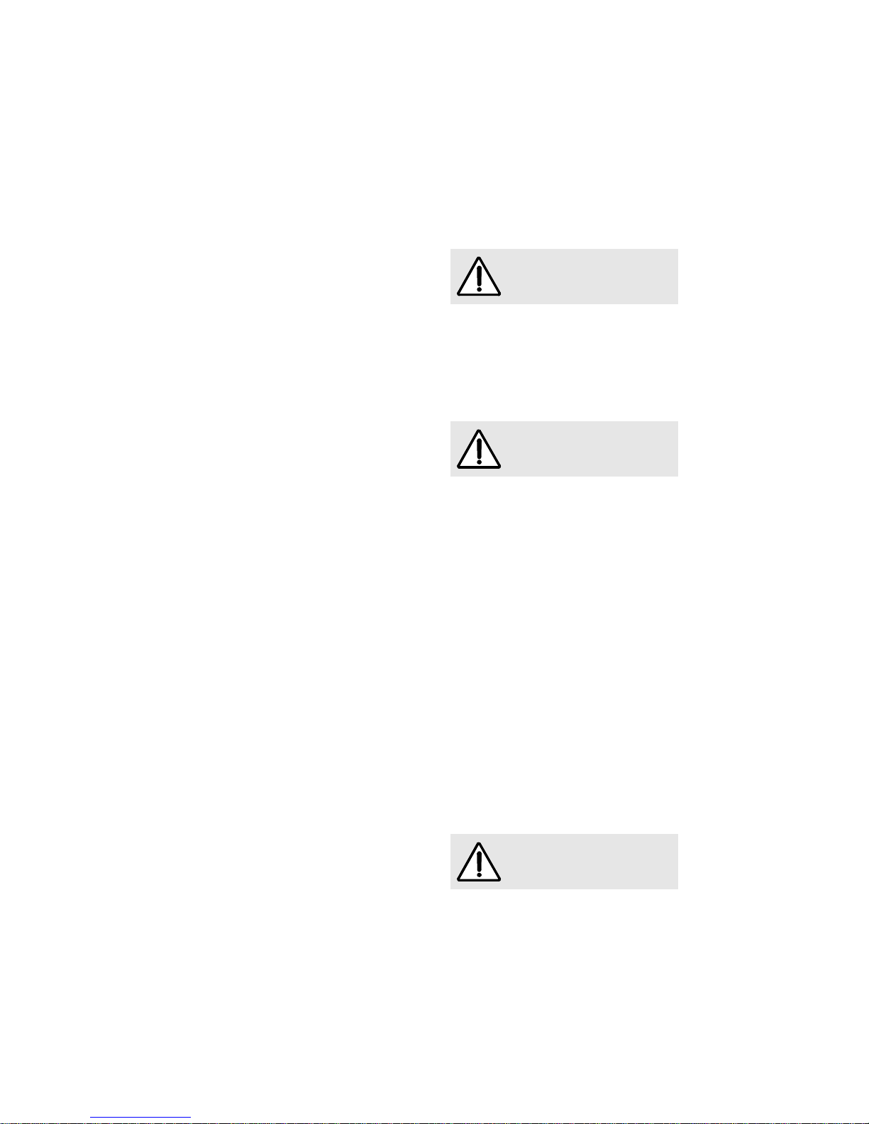
Passen Sie den Vorschub beim Bohren der
Materialstärke an. Zu großer Vorschub führt zu
Überbelastung des Motors, zu unsauberen
Bohrlöchern und zu einem schnelleren
Abstumpfen des Bohrers.
Entfernen Sie die Maschine erst dann vom Werk-
stück,wennder BohrerzumStillstandgekommenist.
Nie bei laufender Maschine an den Bohrer oder
an die Bohreraufnahme greifen.
Die Bohrmaschine darf nur im Freien oder an
offenen Stellen eingesetzt werden, da eine wirk-
same Absaugung nicht möglich ist.
Hinweise zur Wartung und Instandhaltung:
Die regelmäßige Reinigung der Maschine, vor
allem der Bohreraufnahme, stellt einen wichti-
gen Sicherheitsfaktor dar. Vor Beginn dieser
Arbeiten ist der Netzstecker zu ziehen.
Es dürfen nur original MAFELL-Ersatz- und
Zubehörteile verwendet werden. Es besteht
sonst kein Garantieanspruch und keine Haftung
des Herstellers.
3 Rüsten / Einstellen
3.1 Netzanschluss
Die Zimmerei-Bohrmaschine ist schutzisoliert nach
Klasse II.
Vor Inbetriebnahme ist darauf zu achten, dass die
Netzspannung mit der auf dem Leistungsschild der
Maschine angegebenen Betriebsspannung überein-
stimmt.
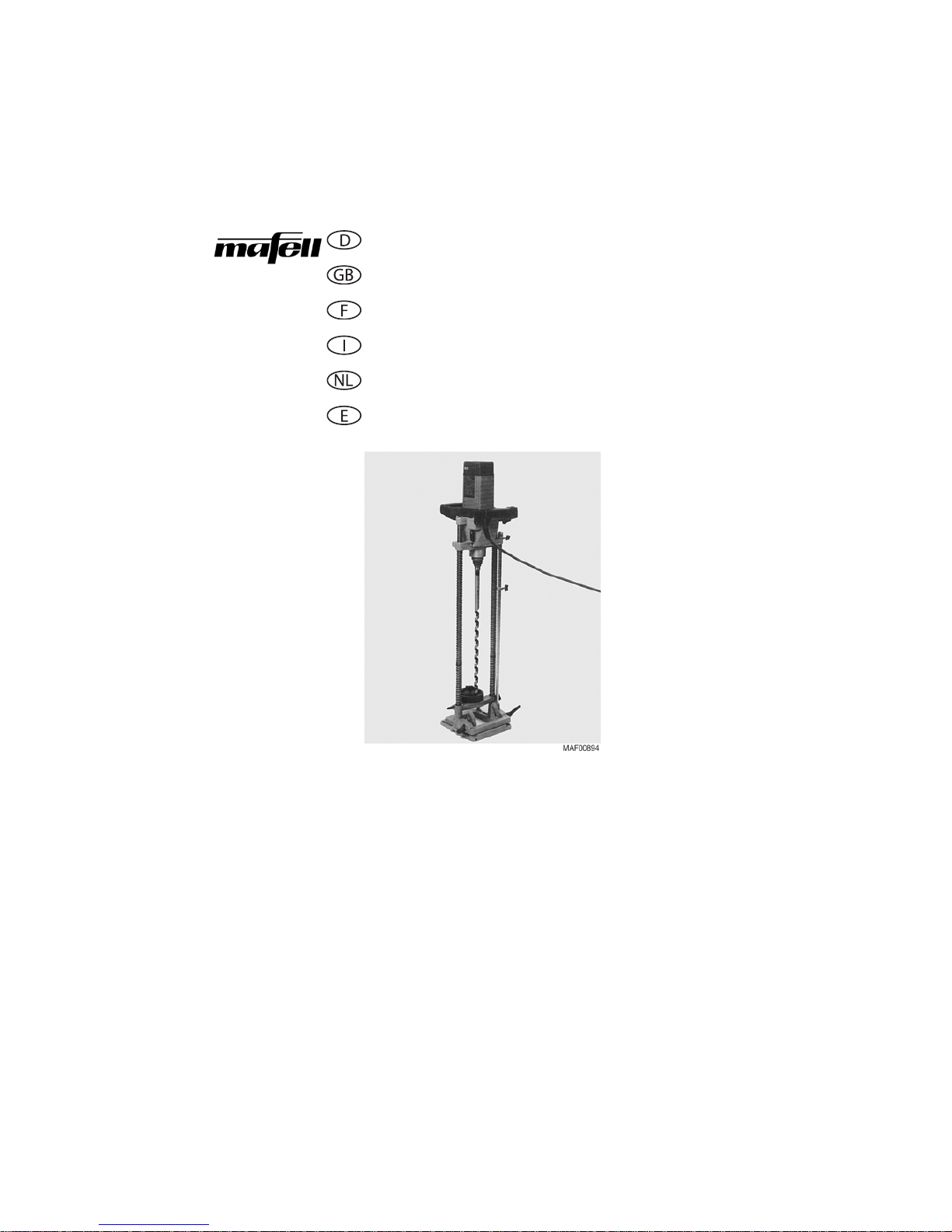
3.2 Werkzeugeinsatz / -wechsel
• Hülse 7 (Abb. 1) anheben, bis die Ringnut 8 am
Schaft sichtbar ist. Werkzeug mit der Fahne in
Richtung der Kerben 9 bis zum Anschlag einfüh-
ren, dann Hülse loslassen.
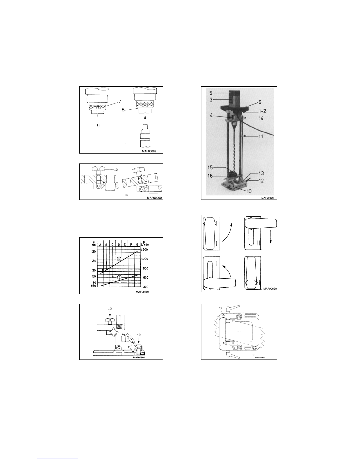
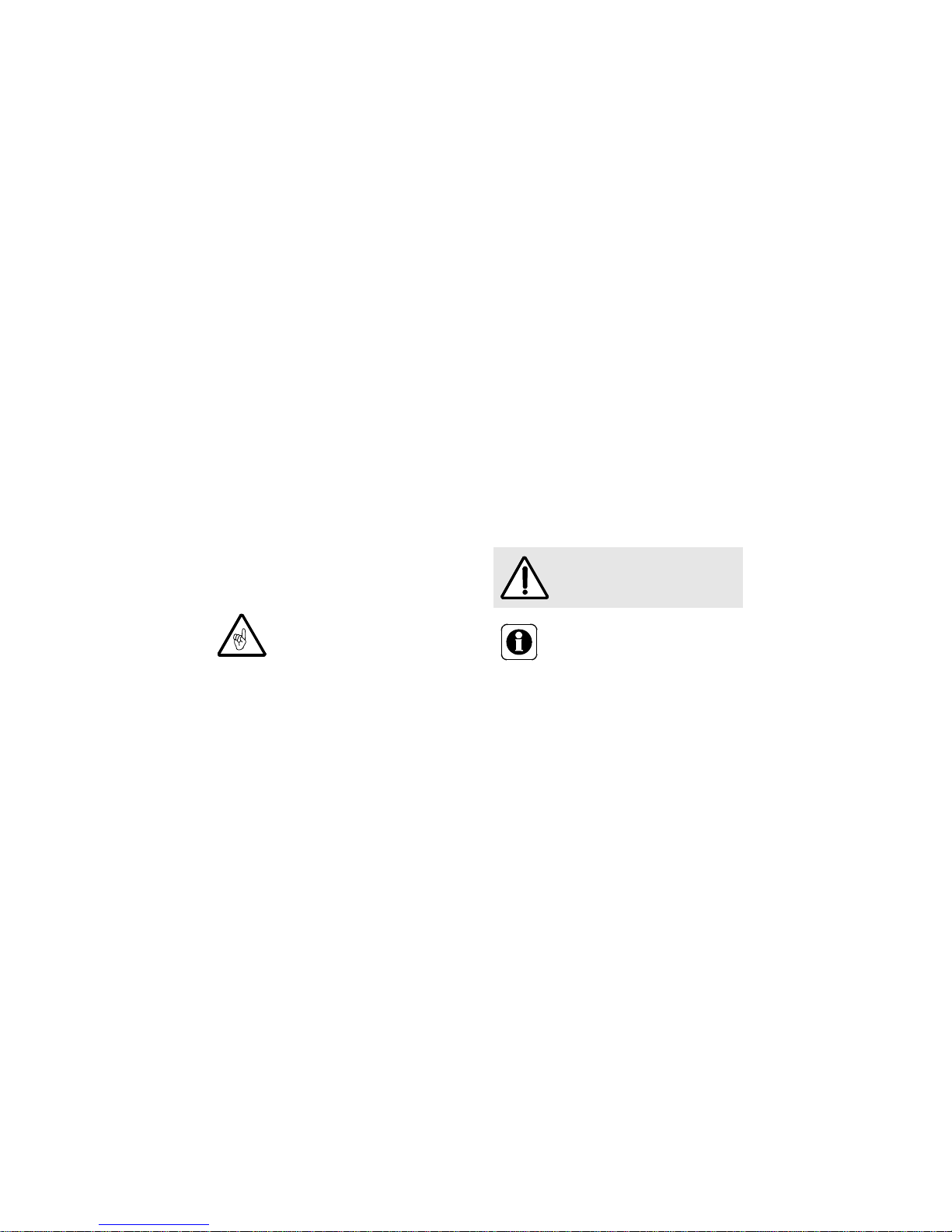
• Bei Verwendung der Bohrerführung muss zuerst
der Kreuzgriff 15 (Abb. 2) so weit gelöst werden,
bis die Bohrplatte 16 geschwenkt werden kann.
Bohrer durch das entsprechende Loch in der
Bohrplatte einführen, Bohrplatte zurückschwen-
ken, Bohrer wie o. a. einführen und Kreuzgriff
festziehen. Kopfsenker mit 80 und 100 mm
nur im Bohrgestell verwenden. Hierzu werden die
oberen (langen) Federn aus dem Bohrgestell ent-
fernt. Ringdübelbohrwerkzeuge dürfen nur im
Sonderbohrgestell (Sonderzubehör) eingesetzt
werden (mit Anschlag).
• Bei Werkzeugwechsel Werkzeug mit einer Hand
festhalten, mit der anderen Hand Hülse 7
(Abb. 1) anheben, bis die Ringnut am Schaft
sichtbar ist. Werkzeug herausnehmen und Hülse
loslassen. Vor dem Einsetzen eines neuen Werk-
zeuges Werkzeugschaft und Werkzeugaufnahme
reinigen.
4Betrieb
Maschine nur ausgeschaltet an das
Netz anschließen.
Vor dem Werkzeugwechsel unbe-
dingt Netzstecker ziehen.
Maschine nur einschalten, wenn das
Werkzeug keinen Kontakt mit dem
Werkstück hat.

-9-
4.1 Ein- und Ausschalten
Kurzbetrieb
• Einschalten: Schalter 1 (Abb. 3) drücken.
• Ausschalten: Schalter loslassen.
Dauerbetrieb
• Einschalten: Schalter 1 und Arretierknopf 2 nach-
einander drücken. Der Motor läuft ohne Druck auf
den Schalter.
• Ausschalten: Schalter 1 eindrücken, bis
Arretierknopf 2 herausspringt, dann Schalter los-
lassen.
4.2 Drehzahleinstellung
Die Bohrmaschine ist mit einem Getriebe und einer
elektronischen Drehzahlregelung ausgestattet. Die
Drehzahl kann stufenlos zwischen 340 und
1450 min-1 eingestellt werden. Die eingebaute Elek-
tronik sorgt beim Einschalten für eine ruckfreie
Beschleunigung und regelt bei Belastung die Dreh-
zahl auf den fest eingestellten Wert nach.
Die erforderliche Drehzahl wird mit Hilfe des Dreh-
zahlschaubildes 3 (Abb. 3) ermittelt (siehe Abb. 4)
und mit dem Getriebeschalthebel 4 (Abb. 3) und
dem Einstellrad 5 eingestellt.
4.3 Arbeitshinweise
• Bolzen 10 (Abb. 6) bis zum Anschlag nach unten
drücken.
• Bohrmaschine nach Anriss ausrichten und so dre-
hen, dass der Bolzen als Verdrehsicherung am
Holz anliegt. Nach dem Einschalten Maschine mit
leichtem Druck nach unten drücken, bis die
Gewindespitze des Bohrers im Holz angepackt
hat. Den weiteren Vorschub übernimmt der Boh-
rer selbst. Bleibt der Bohrer im Loch stecken,
Drehrichtung wechseln. Hierzu Maschine zuerst
ausschalten.
Zum Bohren von Sacklöchern kann die Bohrtiefe mit
dem Anschlagring 11 (Abb. 3) begrenzt werden.
Zum Bohren schräger Löcher Klemmhebel 12
lösen, Maschine nach Skala 13 in gewünschte Lage
schwenken, Klemmhebel festziehen. Bei Verwen-
dung von kürzeren Bohrern kann der Rückhub mit
dem Anschlagring 14 an den Bohrer angepasst wer-
den.
Zum Bohren von Löchern in die Mitte eines Balkens
werden beide Bolzen bis zum Anschlag nach unten
gedrückt und die Maschine so gedreht, dass die Bol-
zen an beiden Seiten des Balkens anliegen - max.
Balkenbreite 22,5 cm (siehe Abb. 6 und Abb. 7).
Für besondere Arbeiten kann der Anschlag kpl.
039 156 (Sonderzubehör) erforderlich sein.
4.4 Zusatzwerkzeuge
Durch den Einsatz von Dübel-, Kopfsenkern und
Ringdübelwerkzeugen usw. ist diese Bohrmaschine
sehr vielseitig verwendbar. Hierzu sind besondere
Merkblätter lieferbar.
5 Wartung und Instandhaltung
5.1 Maschine
Die Maschine muss regelmäßig von abgelagertem
Staub befreit werden. Dabei sollten die Lüftungsöff-
nungen am Motor mit einem Staubsauger gereinigt
werden.
5.2 Werkzeug
Die auf der Maschine benutzten Bohrer sollten
regelmäßig entharzt werden, da saubere Werk-
zeuge die Bohrqualität verbessern.
Zum Reinigen dürfen keine stark alkalischen, son-
dern nur säurefreie Mittel verwendet werden.
Das Entharzen erfolgt durch 24-stündiges Einlegen
der Bohrer in Petroleum oder handelsübliche Ent-
harzungsmittel.
Getriebe nur im Stillstand (oder Aus-
lauf) umschalten (siehe Abb. 5)! Nach
dem Einschalten Drehrichtung des
Werkzeuges überprüfen. Falls erfor-
derlich, Drehrichtung mit dem Schie-
beschalter 6 (Abb. 3) wechseln. Zum
Betätigen des Schiebeschalters muss
die Maschine zuerst ausgeschaltet
werden (mechanische Verriegelung).
Vor Beginn aller Wartungsarbeiten
Netzstecker ziehen!
MAFELL-Maschinen sind wartungsarm
konstruiert. Die eingesetzten Kugellager
sind auf Lebenszeit geschmiert. Nach
längerer Betriebsdauer empfiehlt
MAFELL, die Maschine einer autorisier-
ten MAFELL-Kundendienstwerkstatt zur
Durchsicht zu geben.

-10-
5.3 Lagerung
Wird die Maschine längere Zeit nicht verwendet, ist
diese sorgfältig zu reinigen (siehe Kapitel 5.1).
Blanke Metallteile mit einem Rostschutzmittel ein-
sprühen.
Maschine nur in trockenen Räumen lagern und vor
Witterungseinflüssen schützen.
6 Störungsbeseitigung
Im Folgenden sind einige der häufigsten Störungen und ihre Ursachen aufgeführt. Bei weiteren Störungen wen-
den Sie sich bitte an Ihren Händler oder direkt an den MAFELL-Kundendienst.
7 Sonderzubehör
Anschlag, kpl. Best.-Nr. 039 156
Sonderbohrgestell Best.-Nr. 039 160
Zusatzgriff, kpl. Best.-Nr. 039 203
Austreiber 1 DIN 317 Best.-Nr. 093 001
8 Explosionszeichnung und Ersatzteilliste
Die entsprechenden Informationen zu den Ersatzteilen finden Sie auf unserer Homepage: www.mafell.com
Die Ermittlung der Ursachen von vorliegenden Störungen und deren Beseitigung erfordern stets
erhöhte Aufmerksamkeit und Vorsicht. Vorher Netzstecker ziehen!
Störung Ursache Beseitigung
Maschine lässt sich nicht einschalten Keine Netzspannung vorhanden Spannungsversorgung kontrollieren
Kohlebürsten abgenützt Maschine in die MAFELL-Kunden-
dienstwerkstatt bringen
Maschine bleibt während des Bohrens
stehen Netzausfall Netzseitige Vorsicherungen kontrollie-
ren
Bohrer klemmt Stumpfer Bohrer Bohrer austauschen oder nachschär-
fen

-11-
You will find the following warnings and symbols in these operating instructions:
1 Product information
1.1 Manufacturer´s data
MAFELL AG
P. O. Box 1180, D-78720 Oberndorf/Neckar
Phone +49 7423 812-0, Fax +49 7423 812-218
1.2 Machine identification
Alldata required foridentification of themachine are statedon therating plate whichis attachedto themotor casing.
1.3 Technical data
This symbol indicates where you will find notes for your safety. If disregarded, this may result in
very serious injuries.
This symbol indicates a potentially hazardous situation. If it is disregarded, the product or objects
in its vicinity may be damaged.
This symbol indicates tips for the user and other useful information.
for machines with Art.-Nr. 922 901, 922 905 or 922 920 (ZB 400 E)
923 301 or 923 320 (ZB 600 E)
Pretection class II
CE-mark to declare conformity with the essential health and safety requirements according to
Annex I of the Machinery Directive
Only for EU countries
Do not dispose of electric tools together with household waste material!
In observance of European Directive 2002/96/EC on waste electrical and electronic equipment
and its implementation in accordance with national law, electric tools that have reached the
end of their life must be collected separately and returned to an environmentally compatible
recycling facility.
English
Drilling depth with focussing device ZB 400 E 350 mm (13 25/32 in.)
ZB 600 E 475 mm (18 45/64 in.)
Drilling depthwithout focussing device ZB 400 E 380 mm (14 31/32 in.)
ZB 600 E 505 mm (19 7/8 in.)
Tiltable up to 45°
Drill bit diameter ZB 400 E
10– 30 mm (25/64 –1 3/16 in.)
ZB 600 E
12– 30 mm (15/32 –1 3/16 in.)
Drill bit length ZB 400 E 650 mm (25 19/32 in.)
ZB 600 E 820 mm (32 9/32 in.)
Clamping collar 63 mm (2 31/64 in.)

-12-
Universal motor, radio and TV interference suppressed 230 V~, 50 Hz
Power input (continuous operation) 1200 W
Power output 760 W
1.4 Noise emission
Noise emission values determined according to EN 60745-1 and 60745-2-1:
The noise measurement was recorded using the drill bit included in the standard equipment.
The stated values do not take any series variance into account and are not suitable for determining the immis-
sion sound power level, since this varies depending on the operating time, the machining operation concerned
and environmental factors. The immission sound power level can consequently be determined only in the indi-
vidual instance on the premises of the machine user.
1.5 Vibration
The typical hand-arm vibration is less than 2.5 m/s2.
1.6 Delivery specification
Carpentry drilling machine ZB 400 E or ZB 600 E complete with:
1 drill mount cpl.
1 focussing device
1 wood drill bit 18 mm (45/64 in.)
1 adaptor MK2, Art.-No. 039 139
1 operating manual
1 folder «Safety instructions»
1.7 Use according to intended purpose
The MAFELL carpentry drilling machine ZB 400 E /
600 E is intended exclusively for drilling of solid tim-
ber, using wood drill bits.
The length of the wood drill bits must be 650 mm
(25 19/32 in.) for the ZB 400 E and 820 mm (32 9/32
in.) for the ZB 600 E. A drill bit diameter of 10 to 30
mm (25/64 to 1 3/16 in.) is recommended.
In conjunction with the special drill mount 039 160
(optional accessory) the carpentry drilling machine
ZB 400 E / 600 E is intended for countersinking with
ring-groove drilling tools and head countersinks,
which are offered by MAFELL as optional accesso-
ries.
Any other use beyond this scope is considered as
failing to comply with the intended purpose. The
manufacturer is not liable for any damage caused as
a result of this; the risk is borne solely by the user.
The machine is not suitable for operation in the rain
outdoors or in areas subject to explosion hazards.
Use according to intended purpose also includes
compliance with the operating, maintenance and
repair conditions specified by MAFELL, and adher-
ence to the safety instructions contained in the oper-
ating manual.
Drilling speed – no load 340 – 1450 rpm
Two-stage mechanical gear
Electronic speed control stabilized under load
Clockwise / counterclockwise rotation
Weight without mains cable - with mount ZB 400 E 9,4 kg (20.7 lbs)
ZB 600 E 9,4 kg (20.7 lbs)
Sound power level Workplace-related
emission value
No load 100 dB (A) 89 dB (A)
Operation 101 dB (A) 90 dB (A)

-13-
The carpentry drilling machine ZB 400 E / 600 E
may only be used, set up and serviced by persons
over 18 years of age who are familiar with the
machine and have been instructed as to the dangers
involved. Repair work must be carried out by author-
ized MAFELL dealers or a MAFELL customer ser-
vice station.
The safety regulations applicable in the country of
use, as well as all other generally accepted rules on
safety and occupational medicine, must be
observed.
Unauthorized modifications to the machine preclude
the liability of the manufacturer for any resultant
damage.
1.8 Residual risks
Touching the drill bit or the drill bit mounting
when drilling.
Breakage of the drill bit.
Touching live parts with the housing open and
the mains plug not removed.
Hearing can be impaired when working for long
periods without ear protectors.
Emission of wood dust: a health hazard when
working for long periods without dust extraction.
2 Safety instructions
General instructions:
Never work without the protective equipment
prescribed for the relevant operation and do not
make any modifications to the machine that
could undermine safety.
Children and young persons must not operate
this machine. This rule does not apply to young
persons receiving training and being supervised
by an expert.
Prior to all work, make sure that the safety and
operating equipment is securely attached,
undamaged and in good working condition.
Always be aware of environmental influences.
Do not allow the machine to be exposed to the
rain and do not use the machine in a damp or
wet environment, or in the vicinity of inflam-
mable liquids or gases.
When operating the machine outdoors, use of
an earth-leakage circuit-breaker is recom-
mended.
Do not carry the machine by the cable and do
not remove the mains plug from the socket by
pulling on the cable.
Protect the cable against oil and high tempera-
tures and do not pull it over any sharp edges.
Damaged cables or plugs must be renewed
immediately.
Avoid sharp bends in the cable. Especially when
transporting and storing the machine, do not
wind the cable around the machine.
Only use wood drill bits with the technical data
stated in this manual.
Do not use:
damaged tools
blunt tools
Store the machine in the dry under lock and key
and out of reach of children.
Instructions on the use of personal safety equip-
ment:
Always wear close-fitting industrial clothing and
remove rings, bracelets and watches.
The sound pressure level at the workplace
exceeds 85 dB (A). Users should therefore wear
ear protectors.
Residual risks may also arise owing
to the design of the machine relat-
ing to its intended purpose even if
the machine is used properly and in
compliance with all relevant safety
regulations; e.g.:
Woodworking machines can be
dangerous when in use. You should
therefore always follow the safety
instructions set out in this chapter,
as well as the safety regulations
applicable in the country of use!

-14-
Instructions on operation:
Provide an uncluttered, anti-slip location with
adequate illumination.
Before tool changes, making adjustments and
eliminating malfunctions pull out the mains plug.
Never work with pieces which are too big or too
small for the machine´s capacity.
Thin, long drill bits (> 300 mm / 12 in.) at high
speed should be used only with the focussing
device.
Machine must be switched off before being con-
nected to the mains.
Before switching on, make sure that the drill bit
ist tightly secured and that the Allen key has
been removed.
Whenever possible, secure the workpiece
against slipping and tipping over (e. g. with
screw clamps).
Do not begin drilling until the drill has reached
full speed.
Examine the workpiece for foreign objects.
Never attempt to drill into nails or other metal
objects.
Keep your hands away from the underside of
the workpiece when drilling (risk of injury!).
When drilling, always lead the cable away from
the machine to the rear.
Match the feed rate to the thickness of the work-
piece when drilling. Excessive feedrates over-
load the motor, lead to poorly executed holes
and blunt the drill bit prematurely.
Do not remove the machine from the workpiece
until the drill bit is stationary.
Always keep your hands well away from the drill
bit and the drill bit mounting while the machine
is running.
The drilling machine must be operated only out-
doors or on well ventilated premises as an effec-
tive chip and dust extraction is not possible.
Instructions on service and maintenance:
Regular cleaning of the machine, especially of
the drill bit mounting, is an important safety fac-
tor. Before beginning this task, pull out the
mains plug.
Only original MAFELL spare parts and acces-
sories must be used. Otherwise the manufac-
turer does not offer any warranty and does not
accept any liability.
3 Setting up / Adjusting
3.1 Mains connection
The carpentry drilling machine has Class II protec-
tive insulation (double-insulated).
Before starting up, make sure that the mains voltage
matches the voltage stated on the rating plate.
3.2 Mounting and exchanging drill bits
• Lift sleeve 7 (Fig. 1) until the ring groove 8
around the arbor becomes visible. Insert the drill bit
into the arbor as far as it will go, the flat end of the
drill bit should be inline with thetwo small grooves 9
cut into the end of the arbor. Release the sleeve.
• When using the focussing device the star knob 15
(Fig. 2) should be loosened so that the focussing
disk 16 can be tilted. Insert the drill bit through the
hole of the correct size, return the focussing disk
to its normal position, insert the drill bit into the
arbor as described above and tighten the star
knob. Counter bore heads with of 80 and
100 mm (3 5/32 or 3 15/16 in.) should be used
only in conjunction with the standard drill mount.
For this purpose the upper (long) springs should
be removed. Ringgroove drilling tools should be
used only in conjunction with the special drill
mount with stop plate, available as optional
accessory.
• To exchange the drill bit hold it with one hand, lift
sleeve 7 (Fig. 1) until the ring groove around the
arbor becomes visible. Remove the drill bit and
release the sleeve. Before inserting a new drill bit
make sure that the shaft of the drill bit and the
receiving, toolholding surface of the arbor are clean.
4 Operation
Machine must be switched off before
being connected to the mains.
Always pull out the mains plug before
changing tools.
Do not switch on the machine if the
drill bit is touching the workpiece.

-15-
4.1 Switching on and off
Temporary operation
• Switching on: Press switch 1 (Fig. 3).
• Switching off: Release switch.
Continuous operation
• Switching on: Press switch 1 first and then press
locking button 2. The motor runs without keeping
the switch pressed.
• Switching off: Press switch 1 until locking button 2
trips, then release the switch.
4.2 Adjusting drilling speed
Thisdrillingmachine has agear box and anelectronic
speed control. The drilling speed can be adjusted
continuously between 340 and 1450 rpm. The built-in
electronics ensure a jerk-free acceleration when
switching on and control the speed according to the
value set.
The drilling speed required should be selected by
referring to the diagramme 3 (Fig. 3) (see Fig. 4)
and is set by means of the gear shift lever 4 (Fig. 3)
and the setting wheel 5.
4.3 Operating instructions
• Bolt 10 (Fig. 6) should be pushed down as far as
possible.
• Place the machine in its correct position so that
the drill bit will be exactly above the centre mark-
ing of the hole to be drilled. Turn the machine until
the bolt touches the timber so that it can act as a
stop for torsional force. When the machine has
been switched on it should be pushed down with
light pressure until the threaded tip of the drill bit
has «taken» in the work. Now, the drill will
advance automatically. If the drill bit should get
stuck, the direction of rotation should be reversed.
Before the reverse switch is actuated, the
machine must be switched off.
To drill a blind pocket hole it is possible to set the
drilling depth by means of the depth stop ring 11
(Fig. 3). To drill holes at an angle loosen clamping
lever 12, tilt the machine until the angle desired is
indicated on scale 13, tighten clamping lever again.
Whenusingshortdrillbits the maximumreturn stroke
can be adapted by means of the depth stop ring14.
To drill holes in the middle of a beam both bolts in
the base plate of the drill mount should be pushed
down and the machine should be turned until these
bolts touch the beam on either side - max. width of a
beam 22.5 cm (8 7/8 in.) (see Fig. 6 and Fig. 7).
For special work it may be necessary to use the stop
plate which is available as optional accessory
(Ref. No. 039 156).
4.4 Optional tools
The drilling machine can be used with ring-groove
drilling tools and head countersinks. Special leaflets
on request!
5 Service and maintenance
5.1 Machine
The machine must be cleaned of dust deposits at
regular intervals. When doing so, clean the air vents
on the motor using a vacuum cleaner.
5.2 Tools
The drill bits used on the machine must be freed
from resin regularly, as clean tools improve the drill-
ing quality.
For cleaning only acid-free but no highly alkaline
cleaning agents may be used.
This can be done by soaking the drill bits for 24
hours in paraffin or commercially available resin
remover.
Gear should be shifted only when the
motor has been switched off and the
machine is running out or has stopped
(see Fig. 5)! When the machine has
been switched on the direction of rota-
tion of the drill bit should be checked. If
necessary, the direction of rotation can
be changed by means of the reversing
switch 6 (Fig. 3). Before actuating the
reversing switch the motor should be
switched off (the reversing switch is
mechanically blocked).
Pull out the mains plug before start-
ing on any maintenance work!
MAFELL machines are designed to be
low in maintenance. The ball bearings
used are greased for life. After a pro-
longed period of operation, users are
recommended to have the machine
checked by an authorized MAFELL cus-
tomer service shop.

-16-
5.3 Storage
If the machine is out of service for a lengthy period of
time, it should be thoroughly cleaned (see chapter
5.1). Spray bright metal panels with a rustproofing
agent.
Store the machine only in dry rooms, where it is pro-
tected against weathering.
6 Troubleshooting
Some of the most frequent defects and their causes are listed in the following chart. In case of other defects,
contact your dealer or the MAFELL customer service.
7 Optional accessories
Stop plate, cpl. Ref. No. 039 156
Special drill mount Ref. No. 039 160
Supplementary handle, cpl. Ref. No. 039 203
Ejector drift 1 DIN 317 Ref. No. 093 001
8 Exploded drawing and spare parts list
The corresponding information in respect of spare parts can be found on our homepage: www.mafell.com
The determination of the causes of existing defects and their elimination always require
increased attention and caution. Pull out the mains plug beforehand!
Defect Cause Elimination
Machine cannot be switched on No mains voltage Check power supply
Carbon brushes worn Take the machine to a MAFELL cus-
tomer service shop
Machine stops while drilling is in pro-
gress Mains failure Check mains back-up fuse
Drill bit jams Blunt bit Replace the drill bit or resharpen it

-17-
Vous trouverez dans la présente notice les symboles et mises en garde suivants :
1 Données caractéristiques
1.1 Identification du constructeur
MAFELL AG
B. P. 1180, D-78720 Oberndorf/Neckar
Téléphone +49 7423 812-0, Fax +49 7423 812-218
1.2 Identification de la machine
Toutes les indications pour l'identification de la machine sont présentes sur la plaque signalétique fixée sur le
carter du moteur.
1.3 Caractéristiques techniques
Ce symbole figure partout où vous trouverez des consignes concernant votre sécurité. Leur non
respect peut entraîner des blessures très graves.
Ce symbole signale une situation potentiellement dommageable. Si elle n'est pas évitée, le pro-
duit ou les objets situés à proximité peuvent être endommagés.
Ce symbole signale des astuces d'utilisation et autres informations utiles.
pour les machines ayant l’Art.-Nr. 922 901, 922 905 ou 922 920 (ZB 400 E)
923 301 ou 923 320 (ZB 600 E)
Classe de protecion II
Marque CE pour documenter la conformité avec les exigences fondamentales de sécurité et
de santé suivant appendice I de la directive pour les machines
Pour les pays européens uniquement
Ne pas jeter les appareils électriques dans les ordures ménagères !
Conformément à la directive européenne 2002/96/EG relative aux déchets d'équipements
électriques ou électroniques (DEEE), et à sa transposition dans la législation nationale, les
appareils électriques doivent être collectés à part et être soumis à un recyclage respectueux
de I'environnement.
Français
Profondeur de perçage avec douille de centrage ZB 400 E 350 mm
ZB 600 E 475 mm
Profondeur de perçagesans douille de centrage ZB 400 E 380 mm
ZB 600 E 505 mm
Inclinable jusqu’à 45°
Diamètre de mèche ZB 400 E 10 – 30 mm
ZB 600 E 12 – 30 mm
Longueur de mèche ZB 400 E 650 mm
ZB 600 E 820 mm
Collier de serrage 63 mm

-18-
Moteur universel antiparasité radio / TV 230 V~, 50 Hz
Puissance absorbée en fonctionnement continu 1200 W
Puissance utile 760 W
1.4 Niveau sonore
Les niveaux d’émission sonores tels que définis par la EN 60745-1 et 60745-2-1 s’élèvent à :
La mesure d'émission sonore a été effectuée avec la mèche livrée comme équipement standard.
Les valeurs données ici ne tiennent pas compte d'une possible dispersion et ne peuvent être prises en compte
pour la détermination du niveau d'émission sonore, car ce dernier varie en fonction de la durée d'utilisation, du
type de travail et des conditions environnantes. Le niveau d'émission sonore ne peut donc être établi que chez
l'utilisateur de la machine et au cas par cas.
1.5 Vibration
La vibration typique main-bras ne dépasse pas 2,5 m/s2.
1.6 Equipement standard
Perceuse pour charpente ZB 400 E ou ZB 600 E complette avec :
1 support de perçage, cpl.
1 douille de centrage
1 mèche à bois 18 mm
1 adaptateur MK2, Art.-Nr. 039 139
1 notice d´emploi
1 livret «Instructions de sécurité»
1.7 Utilisation autorisée
La perceuse pour charpente ZB 400 E / 600 E est
prévue exclusivement pour le perçage du bois mas-
sif au moyen de mèches à bois.
La longueur des mèches à bois doit s’élever à 650 mm
pour la ZB 400 E et à 820 mm pour la ZB 600 E. Un
diamètre de mèche de 10 à 30 mm est recommendé.
En combinaison avec le support de perçage spécial
039 160 (accessoire supplémentaire), la perceuse pour
charpente ZB 400 E / 600 E est prévue pour fraiser à
l’aide d’outils de tarière, mèches et fraises à tête que
MAFELL offrecomme accessoires supplémentaires.
Toute autre utilisation est considérée comme non
conforme. Le fabricant décline toute responsabilité
pour tout dommage résultant d'une telle utilisation
non conforme ; le risque est entièrement à la charge
de l'utilisateur.
Cette machine n´est pas utilisable en plein air par
temps de pluie ni dans des enceintes où règne un
danger d´explosion.
La prise en compte des consignes d´utilisation, d´entre-
tien et de maintenance prescrites par le constructeur de
même que les consignes de sécurité figurant dans la
notice d´emploi sont à rattacher à l´utilisation autorisée.
La perceuse pour charpente ZB 400 E / 600 E peut
uniquement être utilisée, équipée et entretenue par
des personnes âgées de plus de 18 ans, qui sont
Vitesse à vide de la mèche 340 – 1450 min-1
Engrenage mécanique à deux étages
Réglage électronique de la vitesse de rotation stabilisée en charge
Rotation à droite / à gauche
Poids sans câble d'alimentation
-
avec support ZB 400 E 9,4 kg
ZB 600 E 9,4 kg
Niveau sonore Niveau sonore
au poste de travail
A vide 100 dB (A) 89 dB (A)
En charge 101 dB (A) 90 dB (A)

-19-
familiarisées avec la machine et ont été instruites
des dangers. Les travaux de réparation doivent être
exécutés par les dépositaires agréés MAFELL ou
par une station service après-vente MAFELL.
Respecter les dispositions de sécurité en vigueur
dans le pays respectif de l'utilisateur ainsi que tous
les règlements généraux de sécurité et de protection
de la santé sur les lieux de travail.
Toute modification de la machine dégage la res-
ponsabilité du constructeur pour les dommages qui
pourraient en résulter.
1.8 Autres risques
Contact avec la mèche ou le logement de la
mèche lors du perçage.
Rupture de la mèche.
Contact avec les parties sous tension lors de
l´ouverture du carter lorsque la fiche n´a pas été
débranchée.
Lésion de l´ouïe lors de travail long et continu
sans protecteurs d´oreilles.
Emission de poussière nuisible à la santé lors
de travail long et continu sans aspiration.
2 Consignes de sécurité
Instructions générales :
Avant tout travail, vérifiez que les dispositifs de
sécurité fonctionnent et ne modifiez rien à la
machine que puisse porter atteinte à la sécurité.
Il est interdit à des enfants ou à des adolescents
de se servir de la machine. Exception faite des
adolescents en cours de leur formation et sous
la surveillance d'un spécialiste compétent.
Avant tout travail, vérifiez que les dispositifs de
sécurité et de travail sont bien fixés, intacts et
fonctionnent sans problèmes.
Préoccupez-vous des conditions extérieures.
N´exposez pas la machine à la pluie et évitez de
travailler dans un environnement humide ou
mouillé, de même qu´à proximité de liquides ou
de gaz inflammables.
Lors de l´utilisation de la machine en plein air, il
est recommandé de l´équiper d´un disjoncteur.
Ne portez pas la machine par son câble et ne
retirez pas la fiche de la prise par le câble.
Veillez à ce que le câble soit protégé contre
l´huile et la chaleur et ne vienne pas en contact
avec des arêtes coupantes.
Les câbles ou les fiches détériorés doivent être
remplacés sans retard.
Evitez de plier le câble. En particulier, ne pas
enrouler le câble autour de la machine pendant
le transport et le stockage de la machine.
N’utilisez que des mèches à bois présentant les
caractéristiques indiquées dans cette notice
d’emploi.
Ne doivent pas être utilisées :
des mèches endommagées
des mèches émoussées
Remettez la machine dans un endroit sec et
fermé, hors de la portée des enfants.
Instructions pour l´utilisation d´équipement de
protection personnel :
Portez toujours des vêtements de travail non flot-
tants et ôtez vos alliances, bracelets et montres.
Le niveau sonore à l'oreille dépasse 85 dB (A).
En conséquence, portez des protecteurs d’oreil-
les pendant le travail.
Instructions pour l´opération :
Veillez à disposer de suffisamment de place
libre et d´un endroit non dérapant, ainsi que
d´un éclairage suffisant.
Même en cas d'utilisation conforme
et nonobstant le respect de toutes
les consignes de sécurité, des ris-
ques résiduels liés à la conception
de la machine, elle-même dictée
par son usage, ne peuvent être
écartés ; p. ex. :
L'utilisation des machines à travail-
ler le bois peut être dangereuse.
Respectez pour cette raison tou-
jours les consignes de sécurité ras-
semblées dans ce chapitre et les
règlements de sécurité en vigueur
dans le pays respectif de
l'utilisateur !

-20-
Avant tout changement d’outil, toute opération
de réglage et avant de remédier à tout dérange-
ment, débranchez la fiche.
Ne travaillez pas de pièces qui seraient soit trop
petites soit trop grosses pour la capacité de la
machine.
Enutilisant de mincesmèchesdont la longueur est
supérieureà 300 mmà une vitesse de rotationéle-
vée, il faut se servir de la douille de centrage.
La machine doit être déclenchée avant de la
raccorder au réseau.
Avant la mise en marche, contrôlez que la mèche
est serrée correctement et que la clé de serrage a
été enlevée.
Assurez toujours la pièce à travailler contre le
danger de glissement et de basculement, p. ex.
à l’aide de serre-joints.
Ne commencez le perçage que lorsque la
mèche a atteint sa pleine vitesse.
Vérifiez qu´il n´y a pas de corps étranges dans
la pièce à travailler. Ne forez pas dans des
objets métalliques, des clous p. ex.
Pendant le perçage, ne mettez pas les mains
sous la pièce à travailler (danger de blessure !).
Lors du forage, ramenez toujours le câble d'ali-
mentation vers l'arrière de la machine.
Durant le perçage, adaptez l'avance à l'épaisseur
du matériau. Une avance trop rapide conduit à
une surcharge du moteur, nuit à la netteté des for-
ures et fait émousser la mèche plus rapidement.
N'éloignez la machine de la pièce à travailler
que lorsque la mèche s'est immobilisée.
Ne touchez pas la mèche ou le logement de la
mèche tant que la machine tourne.
La perceuse ne peut être utilisée qu’en plein air
ou dans des endroits aérés du fait qu’il n’est pas
possible d’avoir une aspiration efficace.
Instructions pour entretien et maintenance :
Le nettoyage régulier de la machine, et en pre-
mier lieu du logement de la mèche, est un fac-
teur important de sécurité. Avant d´y procéder,
débranchez la fiche.
N´utilisez que des pièces détachées et des
accessoires d´origine MAFELL. A défaut de
quoi la garantie du constructeur n´est pas
assurée et sa responsabilité est dégagée.
3 Equipement / Installation
3.1 Raccordement au réseau
La perceuse pour charpente aune protection à dou-
ble isolation de la classe II.
Avant mise en marche, vérifiez que la tension du
réseau correspond bien à la tension indiquée sur la
plaque signalétique de la machine.
3.2 Mise en place d’outil / Changement d’outil
• Tirer la douille 7 (ill. 1) jusqu’à ce que la rainure
annulaire 8 soit visible sur la colonne. Introduire
l’outil avec la queue en direction des encoches 9,
pousser jusqu’en butée, puis relâcher la douille.
• Lors de l’utilisation de la douille de centrage, la
poignée cruciforme 15 (ill. 2) doit d’abord être
débloquée jusqu’à ce que le plateau de perçage
16 puisse être incliné. Introduire la mèche dans le
trou correspondant du plateau de perçage, faire
repivoter le plateau, introduire la mèche comme
décrit plus haut et rebloquer la poignée cruci-
forme. Les fraises à tête de 80 et 100 mm
ne doivent être utilisées qu’avec le support de
perçage spécial. Dans ce cas, retirer du support
de perçage les (longs) ressorts supérieurs. Les
outils de tarière ne doivent être utilisés qu’avec le
support de perçage spécial avec butée (acces-
soire supplémentaire).
• Pour le changement d’outil, tenir fermement l’outil
d’une main et, de l’autre, tirer la douille 7 (ill. 1)
jusqu’à ce que la rainure annulaire soit visible sur
la colonne. Extraire l’outil et relâcher la douille.
Avant la mise en place d’un nouvel outil, nettoyer
la queue et la mèche.
4 Fonctionnement
La machine doit être déclenchée
avant de la raccorder au réseau.
Avant le changement d'outil, débran-
chez toujours la fiche.
Ne démarrez la machine que lorsque
la mèche n'est pas en contact avec
la pièce à travailler.
This manual suits for next models
1
Table of contents
Languages:
Other Mafell Drill manuals

Mafell
Mafell BST 650S Quick guide

Mafell
Mafell A18 M bl User manual

Mafell
Mafell A18 M bl User manual

Mafell
Mafell HB 2 E Guide

Mafell
Mafell A10 M User manual

Mafell
Mafell BS 18 V Guide

Mafell
Mafell A18 Quick guide

Mafell
Mafell BST 650S User manual

Mafell
Mafell A18 M bl Quick guide

Mafell
Mafell A12 Quick guide