Mafell BST 650S Quick guide

BST 650S, 460S, 460, 320
170144.0817/f
Bohrstation Originalbetriebsanleitung 4
Drilling Station Translation of the original operating instructions 12
Station de perçage Traduction de la notice d'emploi originale 20
Stazione di foratura Traduzione delle istruzioni d’uso originali 28
Boorstation Vertaling van de originele gebruiksaanwijzing 36
Estación de taladrado Traducción del manual de instrucciones original 44
Porausasema Käännös alkuperäiskäyttöohjeesta 52
Borrstation Översättning av originalbruksanvisningen 59
Borestation Oversættelse af den originale betjeningsvejledning 67
WARNUNG
Lesen Sie alle Sicherheitshinweise und Anweisungen. Versäumnisse bei der Einhaltung der Sicherheitshinweise und Anweisungen
können elektrischen Schlag, Brand und/oder schwere Verletzungen verursachen. Bewahren Sie alle Sicherheitshinweise und
Anweisungen für die Zukunft auf.
WARNING
Please read all safety instructions and directions. Failure to comply with the safety instructions and directions can cause electric shock, fire
and/or serious injuries. Please retain all safety instructions and directions for future reference.
AVERTISSEMENT
Veuillez lire toutes les consignes de sécurité et instructions. Tout non-respect des consignes de sécurité et instructions risque d'être à
l'origine de décharges électriques, d'incendies et/ou de blessures graves. Conservez toutes les consignes et instructions pour pouvoir les
relire à tout moment.
AVVERTENZA
Leggere tutte le avvertenze di sicurezza e le istruzioni. La mancanza del rispetto delle avvertenze di sicurezza e delle istruzioni possono
causare scossa elettrica, incendio e/o gravi lesioni. Conservare tutte le avvertenze di sicurezza e le istruzioni per il futuro.
WAARSCHUWING
Lees alle veiligheidsaanwijzingen en instructies. Nalatigheid bij het naleven van de veiligheidsinstructies en aanwijzingen kan elektrische
schok, brand en/of ernstige letsels veroorzaken. Bewaar alle veiligheidsaanwijzingen en instructies voor later gebruik.
ADVERTENCIA
Lea todas las indicaciones de seguridad e instrucciones. Si no se cumplen las indicacionesde seguridad e instrucciones, se pueden
producir descargas eléctricas, incendios y/o lesiones graves. Guarde todas las indicaciones de seguridad e instrucciones para el futuro.
VAROITUS
Lue kaikki turvaohjeet ja käyttöohjeet. Laiminlyönti turvaohjeiden ja käyttöohjeiden noudattamisessa voi aiheuttaa sähköiskun, tulipalon
ja/tai vakavia vammoja. Säilytä kaikki turvaohjeet ja käyttöohjeet tulevaisuuden varalle.
VARNING
Läs alla säkerhetsanvisningar och anvisningar. Underlåtenhet att följa säkerhetsanvisningar och anvisningar kan orsaka elstötar, brand
och/eller allvarliga personskador. Behåll alla säkerhetsanvisningar och anvisning för framtida användning.
ADVARSEL
Læs alle sikkerhedshenvisninger og instruktioner. En manglende overholdelse af sikkerhedshenvisningerne og instruktionerne kan føre til
elektrisk stød, brand og/eller alvorlige kvæstelser. Opbevar alle sikkerhedshenvisninger og instruktioner til fremtidig brug.


-12-
English
Table of Contents
1 Signs and symbols .........................................................................................................13
2 Product information ........................................................................................................13
2.1 Manufacturer´s data ....................................................................................................... 13
2.2 Device identification ....................................................................................................... 13
2.3 Technical data ................................................................................................................ 13
2.4 Scope of supply.............................................................................................................. 14
2.5 Use according to intended purpose................................................................................14
2.6 Residual risks ................................................................................................................. 14
3 Safety instructions .......................................................................................................... 14
4 Setting / Adjustment .......................................................................................................15
4.1 Securing the drilling machine ......................................................................................... 15
4.2 Setting the drill guide...................................................................................................... 15
4.3 Tool change.................................................................................................................... 15
4.4 Mounting the insert plate ................................................................................................ 15
4.5 Hoisting rope setting.......................................................................................................15
4.6 Set 0° angle (only BST 650 S and BST 460 S)..............................................................16
4.7 Mounting the copy insert (special accessory)................................................................. 16
4.8 Working with the parallel guide (special accessory).......................................................16
5 Operation........................................................................................................................ 16
5.1 Initial operation ............................................................................................................... 16
5.2 Operating method........................................................................................................... 16
5.3 Drill holes at right angles ................................................................................................ 16
5.4 Slanted drill holes (only BST 650 S and BST 460 S) .....................................................16
5.5 Stud holes ...................................................................................................................... 16
6 Service and maintenance............................................................................................... 16
6.1 Unit................................................................................................................................. 17
6.2 Storage........................................................................................................................... 17
7 Troubleshooting.............................................................................................................. 17
8 Optional accessories ...................................................................................................... 17
9 Exploded drawing and spare parts list ........................................................................... 19

-13-
1 Signs and symbols
This symbol appears at places where you will find instructions for your
own safety.
Non-compliance with these instructions may result in very serious injuries.
This symbol indicates a potentially hazardous situation.
If this situation is not avoided, the product or objects in its vicinity may get
damaged.
This symbol indicates tips for the user and other useful information.
2 Product information
for all units with the item numbers 961216, 961215, 961211, 961210, 961225, 961226, 961227 and 961228
2.1 Manufacturer´s data
MAFELL AG, Beffendorfer Straße 4, D-78727 Oberndorf / Neckar, Phone +49 (0)7423/812-0, Fax +49
(0)7423/812-218
2.2 Device identification
All details required for machine identification are available on the attached rating plate
To reduce the risk of injury, please read the operating instructions.
2.3 Technical data
BST 650 S BST 460 S BST 460 BST 320
max. tool Ø at 0° 130 mm
(5 1/8 in.)
130 mm
(5 1/8 in.)
130 mm
(5 1/8 in.)
130 mm
(5 1/8 in.)
max. tool Ø at 45° 100 mm
(3 15/16 in.)
100 mm
(3 15/16 in.)
- -
max. drilling length 650 mm
(25 19/32 in.)
460 mm
(18 7/64 in.)
460 mm
(18 7/64 in.)
320 mm
(12 19/32 in.)
max. drilling depth 455 mm
(17 29/32 in.)
265 mm
(10 7/16 in.)
300 mm
(11 13/16 in.)
160 mm
(6 19/64 in.)
Clamping range drill guide 8 - 30 mm
(5/16 - 1 3/16
in.)
8 - 30 mm
(5/16 - 1 3/16
in.)
8 - 30 mm
(5/16 - 1 3/16
in.)
8 - 30 mm
(5/16 - 1 3/16
in.)
Swivel range on both sides 45° 45° - -
Weight 6,2 kg
(13.7 lbs.)
5,6 kg
(12.3 lbs.)
5,2 kg
(11.5 lbs.)
5,1 kg
(11.2 lbs.)

-14-
2.4 Scope of supply
Drilling station BST 650 S, BST 460 S, BST 460 or BST 320 complete with:
1 insert panel
1 service tool in bracket on the machine
1 operating manual
1 folder “Safety Instructions”
2.5 Use according to intended purpose
The drilling station is an all-purpose unit for drilling
into wood and wood-like materials. It is used along
with a suitable drill with a collar of Ø 43 mm.
e.g. MAFELL Type HSB
Any other use than described above is not
permissible. The manufacturer cannot be held liable
for any damage arising from such other use.
In order to use the appliance as intended, you must
comply with the operating, maintenance and repair
instructions specified by MAFELL.
2.6 Residual risks
Danger
Even if used in accordance with its
intended purpose and despite
conforming with the safety
instructions, residual risks caused
by the intended use will always
remain.
-Touching the drill bit while drilling
-Drill bit breaks
-Hearing impairment due to working without ear
protection for longer periods of time
-Emission of hazardous wood dust when operated
in closed areas with insufficient ventilation for
longer periods of time.
3 Safety instructions
Danger
Always observe the following safety
instructions and the safety
regulations applicable in the
respective country of use!
General instructions:
-Never work without the protection devices
prescribed for the respective operating sequence
and do not make any changes to the device that
could impair safety.
-Children and adolescents may not operate this
device. This rule does not apply to young persons
receiving training and being supervised by an
expert.
-Consider environmental influences. Do not expose
the device to rain and avoid working near
combustible liquids or gases.
-Chips or slivers must not be removed while the
machine is in operation.
-Store the device in a dry, locked place outside the
reach of children.
Instructions on the use of personal protective
equipment:
-Always wear ear protectors during work.
-Always wear protective goggles during work.
-Always where a dust mark during work.
Instructions on operation:
-Provide for an unobstructed and slip-proof location
with adequate lighting.
-Check to ensure that the tool is clamped correctly
before switching it on.
-As far as possible ensure that the workpiece is
secured from slipping away and toppling by using
e.g. tension clamps.
-Ensure that the area where the drill bit emerges
from the workpiece is free of obstacles.
-Examine the workpiece for foreign objects.
-Never reach under the workpiece while working
(risk of injury!).

-15-
-Check the unit before every use. If damaged, do
not use the unit. Only expert personnel may carry
out repairs. Never open the unit yourself.
-When drilling adjust the feed to the drill bit Ø and
material thickness. Too large of a feed leads to
motor overload, unclean drill holes and an
accelerated blunting of the brill bit.
-Never take hold of the tool while the machine is in
operation.
Instructions on service and maintenance:
-To ensure safety it is essential to regularly clean
the unit, above all the guides. The drill must be
removed from the unit before starting this work.
-Only original MAFELL spare parts and accessories
may be used. Otherwise, the manufacturer will not
accept any warranty claims and cannot be held
liable.
4 Setting / Adjustment
4.1 Securing the drilling machine
Place a suitable drill with drill bit into the locating hole
and clamp the machine with the handle 1 (Fig. 1).
Danger
Follow the safety instructions for
the drill!
4.2 Setting the drill guide
The drill guide is continuously
variable for drill bits between Ø 8
mm and Ø 30 mm.
Unfasten the wing nut 3 (Fig. 1) Use the wing nut to
turn the setting disc so that the guide sleeves barely
touch the drill bit circumference. Tighten the wing nut
again.
The height of the drill guide can be
adjusted along the column.
To do this unfasten both cylinder
screws, 2 (Fig. 1) move the drill
guides into the desired position and
tighten the cylinder screws again.
The drill guide can be removed
from the column for machining
tools larger than Ø 30 mm.
To do this unfastern both cylinder
screws 2 (Fig. 1) until the drill guide
can be removed.
In order to re-attach the drill guide,
put it in place on the column and
tighten the cylinder screws.
4.3 Tool change
Danger
Always remove the drill's power
plug from the power supply before
changing tools.
Completely open the drill guide (see section 4.2),
open the boring socket of the drill and remove the
tool.
Place the new tool into the drill and set the drill guide
(see section 4.2).
4.4 Mounting the insert plate
Using the insert panel is
recommended for drilling into end-
grain wood or wood with thin
widths.
Set the insert panel from below into the base plate
and tighten it with both countersink screws 12 (Fig.
3).
4.5 Hoisting rope setting
Danger
The hoisting rope can be
tensioned. The rope guide can be
catapulted.
The returning force of the hoisting
rope is continuously adjustable,
which is especially advantageous
for horizontal drill holes.
Open the tension lever 10 (Fig. 2) and move the rope
guide to 9 to the desired position.
Re-tighten the tension lever.

-16-
4.6 Set 0° angle (only BST 650 S and BST 460 S)
Unfasten the handle 8 (Fig. 2) by turning it. Press the
button 11 and keep it pressed. Swivel the column
slowly toward the 0° angle (angle scale) until the
push rod snaps into place. Turn the button to the left
and then release it. Tighten the handle.
The 0° angle is then locked into place. In order to
release the lock, press the button downward and turn
it toward the right until the push rode snaps out of
place.
4.7 Mounting the copy insert (special accessory)
A copy insert (special accessory)
can be used for hole patterns and
rows of holes.
Templates with Ø 25 mm of wood
or metal can be used for drilling the
holes of repreated drilling patterns.
Set the copy insert from below into the base plate and
tighten it with both countersink screws 12 (Fig. 3).
4.8 Working with the parallel guide (special
accessory)
The parallel guide (special accessory) can be
attached on all four sides to the base plate and be
tightened with the wing nuts included in delivery.
The base plate has read-off edges on three sides;
you can use them to read the scale on the parallel
guide.
Furthermore the parallel guide can be used as a twin
pad simply by turning it over.
The parallel guide also has a lateral stop that can be
inserted into the side-face from both sides and then
tightened with the Allen wrench included in delivery.
The scale can be read on the edges at the end of the
side-face.
5 Operation
5.1 Initial operation
Personnel entrusted to work with the machine must
be made aware of the operating instructions, calling
particular attention to the chapter "Safety
instructions".
Ensure that the tool is properly fastened.
5.2 Operating method
Switch on the drill.
Use moderate pressure to press the running drill
downward until the crest of the drill thread engages
the wood. The drill then automatically continues the
feed. Once a hole has been drilled, the built-in
Zugseilden Schlitten wieder zurück. It might be
necessary to help by pulling on the handle of the drill.
The return force of the hoisting rope is continuously
adjustable (see section 4.5).
5.3 Drill holes at right angles
First set the column to the °0 angle (only BST 650 S
and BST 460 S)
(see section 4.6)
Align the drilling station to the break of the desired
bore hole. The break indicator on the base plate or
insert panel are helpful for this.
5.4 Slanted drill holes (only BST 650 S and BST
460 S)
The column can be swivelled to the
left and right by 45 degrees°.
The pivot axis is on the workpiece surface so that the
break indicator of the base plate can be used even
when swivelled.
Unfasten the handle 8 (Fig. 2) by turning it. Swivel the
column to the desired position accordinf to the angle
scale 7. Re-tighten the handle.
5.5 Stud holes
Unfasten the tension lever 4 (Fig. 1). Set the depth
stop 5 according to the depth scale 6 and re-tighten
the tension lever. (Take the drill bit distance above
the wood into account).
The surfaces of the depth stop marked in red and the
die coloured depth scale are helpful for this.
6 Service and maintenance
Danger
Always remove the drill from the
drilling station before working on
the unit.
-17-
After a significant operating time
MAFELL recommends that the unit
be inspected by an authorised
MAFELL customer service repair
shop.
6.1 Unit
The unit must be regularly dusted. The guides should
be cleaned with a vacuum cleaner.
Occasional spraying with machine oil maintains the
ease of movement of joints and guide pieces.
The storage place must be dry and frost-protected.
If the device fails despite diligent manufacturing and
test procedures, the repair must be carried out by an
authorised customer service station for MAFELL
products.
Danger
Only use MAFELL accessories and
spare parts. Components of which
their replacement has not been
described must be replaced by a
MAFELL customer service repair
shop.
6.2 Storage
If the unit is not used for a long period of time, it must
be cleaned carefully (see Chapter 6.1). Spray bright
metal panels with a rust inhibitor.
7 Troubleshooting
Danger
Determining the causes for existing defects and eliminating these always
requires increased attention and caution. Pull the mains plug beforehand!
Some of the most frequent defects and their causes are listed in the following chart. In case of other defects,
contact your dealer or the MAFELL customer service.
Defect Cause Elimination
Drill bit is stuck Blunt drill bit Replace or re-sharpen drill bit
Drill bit becomes very hot near the
drill guide
Drill guide lies too taut on the drill
bit
Rest the drill guide only lightly
adjacent to the drill bit
The column cannot be sufficiently
tightened after swivelling (only
BST 650 S and BST 460 S)
Column clamp improperly set Adjust the hex nut of the column
clamp
8 Optional accessories
-Parallel guide fence cpl. Order No. 204407
-Template guide Ø 24,8 / 18 Order No. 204290
-Template drill Ø 25 Order No. 090276
-Drilling machine retaine Ø 57 Order No. 204476

-18-
BST 650 S
-Drill box 650 with wood drill Ø 12, 14, 16, 18, 20 mm Order No. 093292
-Wood drill Ø 10 x 650 Order No. 090240
-Wood drill Ø 12 x 650 Order No. 090241
-Wood drill Ø 14x 650 Order No. 090242
-Wood drill Ø 16 x 650 Order No. 090243
-Wood drill Ø 18 x 650 Order No. 090244
-Wood drill Ø 20 x 650 Order No. 090245
-Wood drill Ø 22 x 650 Order No. 090246
-Wood drill Ø 24 x 650 Order No. 090247
-Wood drill Ø 26 x 650 Order No. 090248
-Wood drill Ø 28 x 650 Order No. 090249
-Wood drill Ø 30 x 650 Order No. 090250
BST 460 S / BST 460
-Drill box 460 with wood drill Ø 8, 10, 12, 14, 16, 18 mm Order No. 093291
-Wood drill Ø 8 x 460 Order No. 090251
-Wood drill Ø 10 x 460 Order No. 090252
-Wood drill Ø 12 x 460 Order No. 090253
-Wood drill Ø 14 x 460 Order No. 090254
-Wood drill Ø 16 x 460 Order No. 090255
-Wood drill Ø 18 x 460 Order No. 090256
-Wood drill Ø 20 x 460 Order No. 090257
-Wood drill Ø 22 x 460 Order No. 090258
-Wood drill Ø 24 x 460 Order No. 090259
-Wood drill Ø 26 x 460 Order No. 090260
-Wood drill Ø 28 x 460 Order No. 090261
-Wood drill Ø 30 x 460 Order No. 090262

-19-
BST 320
-Drill box 320 with wood drill Ø 8, 10, 12, 14, 16, 18 mm Order No. 093290
-Wood drill Ø 6 x 320 Order No. 090279
-Wood drill Ø 7 x 320 Order No. 090280
-Wood drill Ø 8 x 320 Order No. 090263
-Wood drill Ø 9 x 320 Order No. 090264
-Wood drill Ø 10 x 320 Order No. 090265
-Wood drill Ø 12 x 320 Order No. 090266
-Wood drill Ø 14 x 320 Order No. 090267
-Wood drill Ø 16 x 320 Order No. 090268
-Wood drill Ø 18 x 320 Order No. 090269
-Wood drill Ø 20 x 320 Order No. 090270
-Wood drill Ø 22 x 320 Order No. 090271
-Wood drill Ø 24 x 320 Order No. 090272
-Wood drill Ø 26 x 320 Order No. 090273
-Wood drill Ø 28 x 320 Order No. 090274
-Wood drill Ø 30 x 320 Order No. 090275
9 Exploded drawing and spare parts list
The corresponding information in respect of spare parts can be found on our homepage: www.mafell.com
Other manuals for BST 650S
1
This manual suits for next models
3
Table of contents
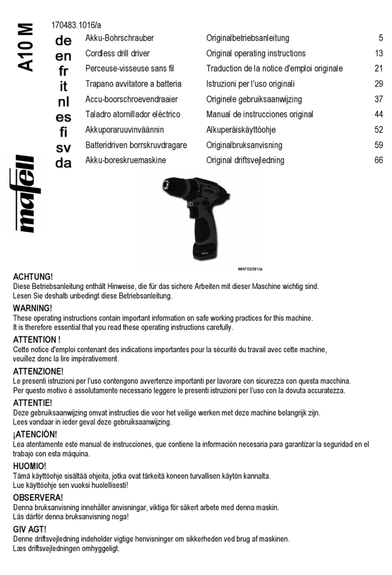
Other Mafell Drill manuals

Mafell
Mafell A18 Quick guide

Mafell
Mafell A18 M bl Quick guide

Mafell
Mafell A18 M bl User manual

Mafell
Mafell ZB 400E User manual

Mafell
Mafell ZB 100 ES User manual

Mafell
Mafell A12 Quick guide

Mafell
Mafell A10 M User manual

Mafell
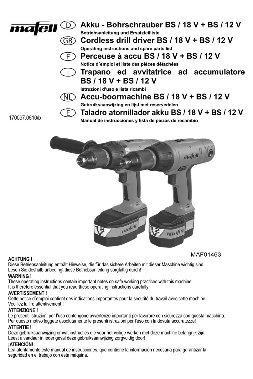
Mafell BS 18 V Guide

Mafell
Mafell A18 M bl User manual

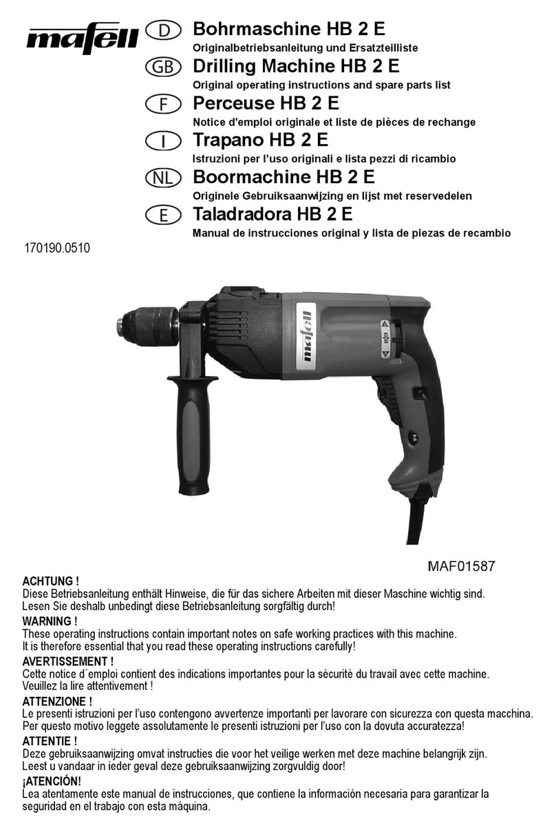
Mafell
Mafell HB 2 E Guide