AIR Series User Manual rev 1.1
info@mag-audio.com
Tel./Fax: +38 044 277-47-89 www.mag-audio.com
9
3. AIR series
3.1. Introduction
AIR series has been created as the series of
installation-dedicated speakers, backed-up with
various mounting hardware options for ease
and versatility of set-up. Available weatherproof
capability makes AIR series even more adaptable,
ready to be used in outdoor installations as well.
Benefiting from truly point-source design based on
coaxial and full-range speakers, AIR series opens a
new dimension for speaker placement to achieve
best possible coverage while keeping sound system
visual imprint to the lowest possible minimum.
Together with installation subwoofers, AIR cabinets
are capable to deliver significant sound pressure
required by modern clubs, bars, entertainment
centers, malls, and open-air theme parks.
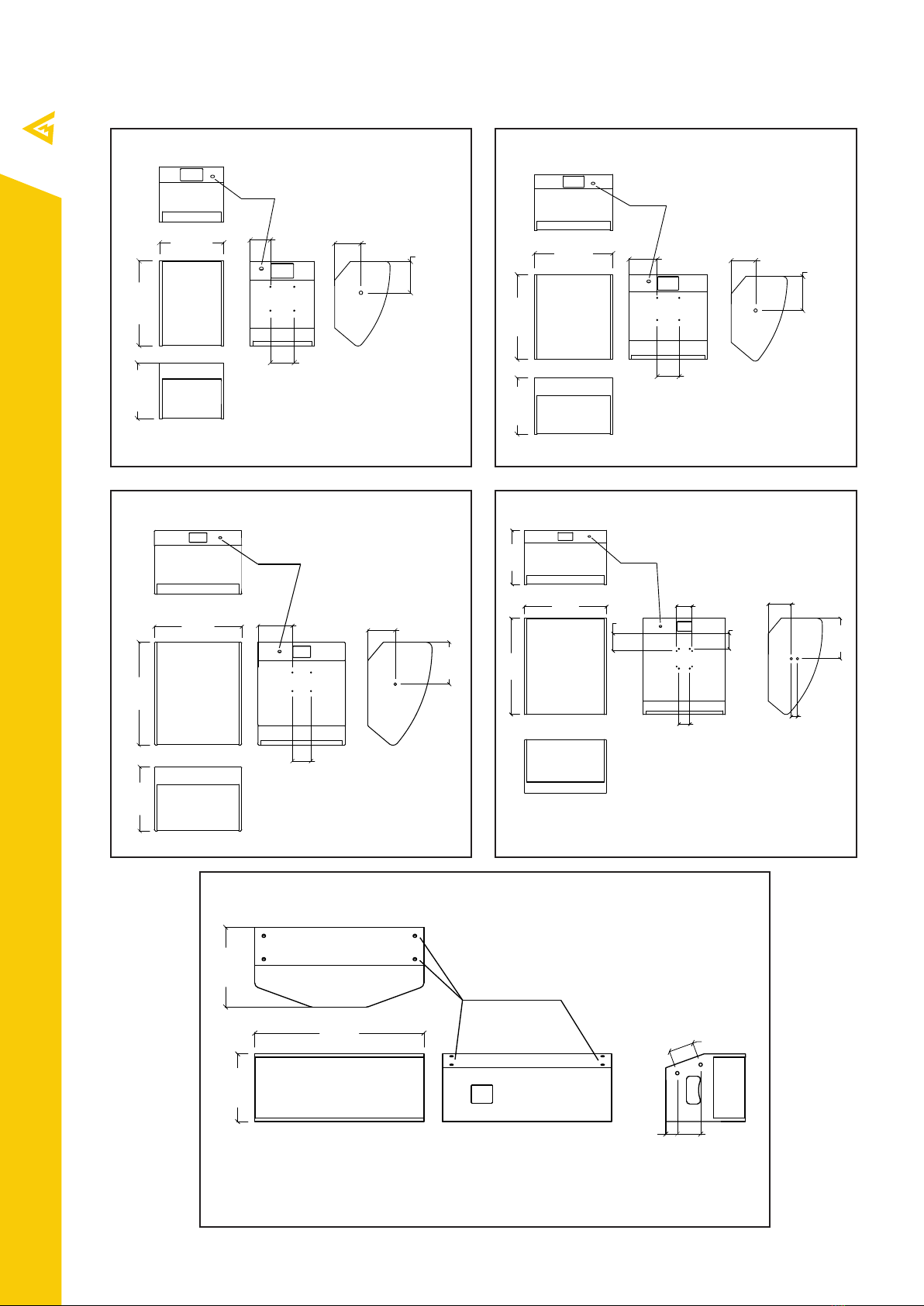
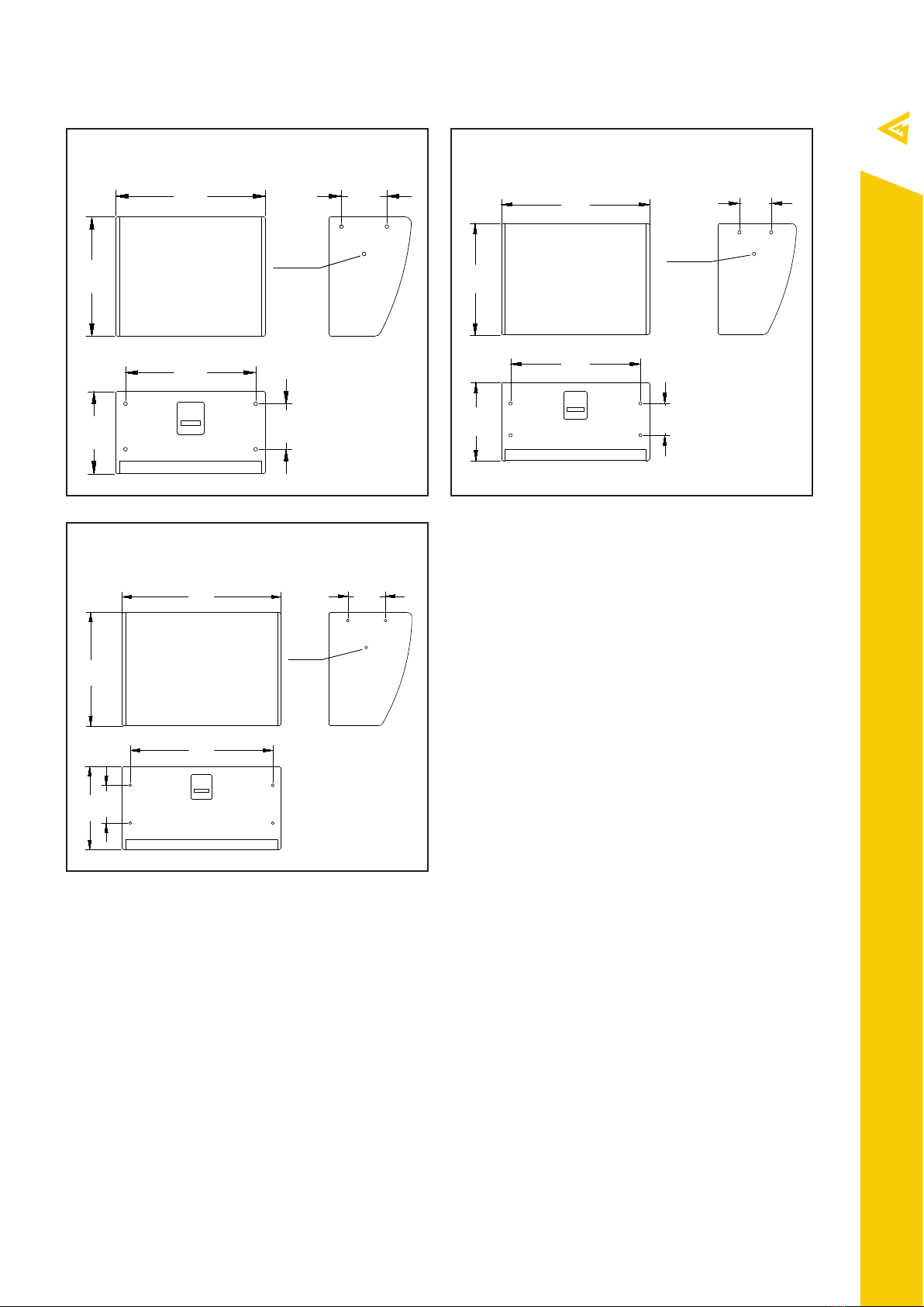
3.2. AIR series speaker models
AIR series includes following speaker models:
AIR-62-8-BK part number 00-0004538
AIR-62-8-WH part number 00-0021201
AIR-62-16-BK part number 00-0005612
AIR-62-16-WH part number 00-0021200
AIR-82-4-BK part number 00-0006405
AIR-82-4-WH part number 00-0021203
AIR-82-8-BK part number 00-0004537
AIR-82-8-WH part number 00-0021204
AIR-82-16-BK part number 00-0005613
AIR-82-16-WH part number 00-0021202
AIR-122-4-BK part number 00-0017875
AIR-122-4-WH part number 00-0021194
AIR-122-8-BK part number 00-0017875
AIR-122-8-WH part number 00-0021195
AIR-152-4-BK part number 00-0017876
AIR-152-4-WH part number 00-0021196
AIR-152-8-BK part number 00-0004540
AIR-152-8-WH part number 00-0021197
AIR-210-4-BK part number 00-0005615
AIR-210-4-WH part number 00-0021198
AIR-210-8-BK part number 00-0004387
AIR-210-8-WH part number 00-0021199
AIR-62-8-IP-BK part number 00-0019989
AIR-62-8-IP-WH part number 00-0021220
AIR-62-16-IP-BK part number 00-0019990
AIR-62-16-IP-WH part number 00-0021219
AIR-82-4-IP-BK part number 00-0019987
AIR-82-4-IP-WH part number 00-0021223
AIR-82-8-IP-BK part number 00-0017488
AIR-82-8-IP-WH part number 00-0021224
AIR-82-16-IP-BK part number 00-0019988
AIR-82-16-IP-WH part number 00-0021221
AIR-122-4-IP-BK part number 00-0019986
AIR-122-4-IP-WH part number 00-0021213
AIR-122-8-IP-BK part number 00-0007159
AIR-122-8-IP-WH part number 00-0021214
AIR-152-4-IP-BK part number 00-0019991
AIR-152-4-IP-WH part number 00-0021215
AIR-152-8-IP-BK part number 00-0019992
AIR-152-8-IP-WH part number 00-0021216
AIR-210-4-IP-BK part number 00-0019994
AIR-210-4-IP-WH part number 00-0021217
AIR-210-8-IP-BK part number 00-0019993
AIR-210-8-IP-WH part number 00-0021218
AIR-S12-4-BK part number 00-0006521
AIR-S12-4-WH part number 00-0021205
AIR-S12-8-BK part number 00-0004550
AIR-S12-8-WH part number 00-0021206
AIR-S15-4-BK part number 00-0006522
AIR-S15-4-WH part number 00-0021207
AIR-S15-8-BK part number 00-0004535
AIR-S15-8-WH part number 00-0021208
AIR-S18-4-BK part number 00-0006523
AIR-S18-4-WH part number 00-0021209
AIR-S18-8-BK part number 00-0004536
AIR-S18-8-WH part number 00-0021210
AIR-S12-4-IP-BK part number 00-0019969
AIR-S12-4-IP-WH part number 00-0021226
AIR-S12-8-IP-BK part number 00-0019968
AIR-S12-8-IP-WH part number 00-0021227
AIR-S15-4-IP-BK part number 00-0019973
AIR-S15-4-IP-WH part number 00-0021228
AIR-S15-8-IP-BK part number 00-0019972
AIR-S15-8-IP-WH part number 00-0021229
AIR-S18-4-IP-BK part number 00-0019970
AIR-S18-4-IP-WH part number 00-0021231
AIR-S18-8-IP-BK part number 00-0019971
AIR-S18-8-IP-WH part number 00-0021232