manuals.online logo
Brands
  1. Home
  2. •
  3. Brands
  4. •
  5. Magma
  6. •
  7. Recording Equipment
  8. •
  9. Magma MDR 24/96 User manual

Magma MDR 24/96 User manual

Popular Recording Equipment manuals by other brands

ThermoFisher Scientific Dionex DRS 600 Installation checklist

ThermoFisher Scientific

ThermoFisher Scientific Dionex DRS 600 Installation checklist

Shure ANIUSB-Matrix user guide

Shure

Shure ANIUSB-Matrix user guide

Nady Audio HE-1 user guide

Nady Audio

Nady Audio HE-1 user guide

AUDAC APM 01 User manual & installation guide

AUDAC

AUDAC APM 01 User manual & installation guide

Teac GF-350 owner's manual

Teac

Teac GF-350 owner's manual

Fractal Audio MFC-101 MARK III owner's manual

Fractal Audio

Fractal Audio MFC-101 MARK III owner's manual

bmcm USB-OI16 manual

bmcm

bmcm USB-OI16 manual

HHB BurnIT CDR-830 Service manual

HHB

HHB BurnIT CDR-830 Service manual

GE VersaMax IC200CPUE05 manual

GE

GE VersaMax IC200CPUE05 manual

IntesisBox MH-RC-MBS-1 user manual

IntesisBox

IntesisBox MH-RC-MBS-1 user manual

Attero Tech unD4l user manual

Attero Tech

Attero Tech unD4l user manual

Sennheiser UI 765 instruction manual

Sennheiser

Sennheiser UI 765 instruction manual

Sony RCD-W1 Operating Instructions  (primary... Service manual

Sony

Sony RCD-W1 Operating Instructions (primary... Service manual

Roland Planet-P  MKS-10 owner's manual

Roland

Roland Planet-P MKS-10 owner's manual

Roland BOSS GT-PRO Turbostart

Roland

Roland BOSS GT-PRO Turbostart

8x8 Inc Valcom V-2001A manual

8x8 Inc

8x8 Inc Valcom V-2001A manual

Waves SUB Align user guide

Waves

Waves SUB Align user guide

Mitsubishi Electric MAC-334IF-E installation manual

Mitsubishi Electric

Mitsubishi Electric MAC-334IF-E installation manual

manuals.online logo
manuals.online logoBrands
  • About & Mission
  • Contact us
  • Privacy Policy
  • Terms and Conditions

Copyright 2025 Manuals.Online. All Rights Reserved.

24 TRACK/24 BIT, DIGITAL AUDIO HARD DISK RECORDER
QUICK START GUIDE
MDR 24MDR 24
MDR 24MDR 24
MDR 24/96
2
MDR 24/96
MDR 24/96
1. Read instuctions — Read, understand and follow all safety and operating
instructions before using the MDR24/96.
2. Retain Instructions — Keep these safety and operating instructions for future
reference.
3. Heed Warnings — Follow all warnings on the MDR24/96 and in these
operating instructions.
4. Water and Moisture — Do not use the MDR24/96 near water – for
example, near a bathtub, kitchen sink, garden hose, incontinent poodle,
sweaty drummer, etc. – or when condensation has formed on the unit.
5. Heat and Ventilation — Locate the MDR24/96 away from heat sources such
as radiators, campfires, compost pits, heliarc welders, magma flows, etc. Do
not block MDR24/96 ventilation openings or install in spaces that prevent
adequate air circulation to the unit.
6. Power Sources — Connect the MDR24/96 only to a power source of the type
described in these operating instructions or as marked on the MDR24/96.
7. Power Cord Protection — Route power supply cords so that they are not likely
to be walked upon, tripped over, or abraded by items placed upon or against
them. Pay particular attention to cords at plugs, convenience receptacles, and
the point where they exit the MDR24/96.
8. Object and Liquid Entry — Do not drop objects or spill liquids into the
MDR24/96. Clean only with a damp cloth; do not clean with liquid or aerosol
cleaners.
9. Attachments — Use the MDR24/96 with only the accessories specified in
this manual.
10. Damage Requiring Service — The MDR24/96 should be serviced only by
qualified service personnel when:
A. The power supply cord or the plug has been damaged; or
B. Objects have fallen onto, or liquid has spilled into the unit; or
C. The unit has been exposed to rain or water; or
D. The unit does not appear to operate normally or exhibits a marked
change in performance; or
E. The unit has been dropped, or its chassis damaged.
11. Servicing — Do not attempt to service the MDR24/96. All servicing
should be referred to the Mackie Service Department.
12. Lightning — Unplug the MDR 24/96 during lightning storms or when
unused for long periods of time.
13. Grounding and Polarization — To prevent electric shock, do not use the
MDR24/96 polarized plug with an extension cord, receptacle or other
outlet unless the blades can be fully inserted to prevent blade exposure.
Do not defeat the MDR24/96 grounding by plugging into an ungrounded
receptacle or ground lift adapter.
This apparatus does not exceed the Class A/Class B (whichever is applicable)
limits for radio noise emissions from digital apparatus as set out in the radio
interference regulations of the Canadian Department of Communications.
ATTENTION — Le présent appareil numérique n’émet pas de bruits
radioélectriques dépassant las limites applicables aux appareils numériques de
class A/de class B (selon le cas) prescrites dans le réglement sur le brouillage
radioélectrique édicté par les ministere des communications du Canada.
This product has been tested and complies with the
following standards and directives as set forth by the
European Union:
* EN 55022 Radiated and Conducted Emissions
* EN 61000-4-2 Electrostatic Discharge Immunity
* EN 61000-4-3 RF Electromagnetic Fields Immunity
* EN 61000-4-4 Electrical Fast Transient/Burst Immunity
* EN 60950/IEC 950 Electrical Safety Requirements
FCC Information
NOTE: This equipment has been tested and found to comply
with the limits for a Class A digital devices, pursuant to Part 15
of the FCC ules. These limits are designed to provide
reasonable protection against harmful interference when the
equipment is operated in a commercial installation. This
equipment generates, uses, and can radiate radio frequency
energy and, if not installed and used in accordance with the
instruction manual, may cause harmful interference to radio
communications. Operation of this equipment in a residential
area is likely to cause harmful interference in which case the
user will be required to correct the interference at his own
expense.
CAUTION AVIS
ISK OF ELECT IC SHOCK
DO NOT OPEN
ISQUE DE CHOC ELECT IQUE
NE PAS OUV I
CAUTION: TO EDUCE THE ISK OF ELECT IC SHOCK
DO NOT EMOVE COVE (O BACK)
NO USE -SE VICEABLE PA TS INSIDE
EFE SE VICING TO QUALIFIED PE SONNEL
ATTENTION: POUR EVITER LES RISQUES DE CHOC
ELECTRIQUE, NE PAS ENLEVER LE COUVERCLE. AUCUN
ENTRETIEN DE PIECES INTERIEURES PAR L’USAGER. CONFIER
L’ENTRETIEN AU PERSONNEL QUALIFIE.
AVIS: POUR EVITER LES RISQUES D’INCENDIE OU
D’ELECTROCUTION, N’EXPOSEZ PAS CET ARTICLE
A LA PLUIE OU A L’HUMIDITE
The lightning flash with arrowhead symbol within an equilateral
triangle is intended to alert the user to the presence of uninsulated
"dangerous voltage" within the product’s enclosure, that may be
of sufficient magnitude to constitute a risk of electric shock to persons.
Le symb le clair avec p int de fl che l’int rieur d’un triangle
quilat ral est utilis p ur alerter l’utilisateur de la pr sence
l’int rieur du c ffret de "v ltage dangereux" n n is l d’ampleur
suffisante p ur c nstituer un risque d’ l ctr cuti n.
The exclamation point within an equilateral triangle is intended to
alert the user of the presence of important operating and maintenance
(servicing) instructions in the literature accompanying the appliance.
Le p int d’exclamati n l’int rieur d’un triangle quilat ral est
empl y p ur alerter les utilisateurs de la pr sence d’instructi ns
imp rtantes p ur le f ncti nnement et l’entretien (service) dans le
livret d’instructi n acc mpagnant l’appareil.
Important Sa ety Instructions
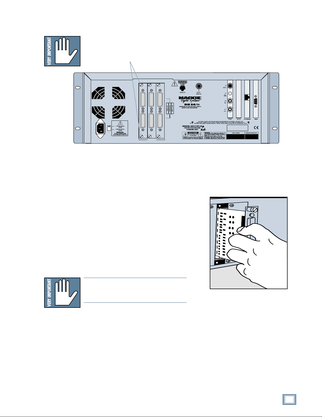
WARNING — Before applying power to the MDR24/96, make sure that the
Voltage Selector switch next to the AC inlet jack on the rear panel is set to
the line voltage used in your region. Powering-on the MDR24/96 with
the Voltage Selector switch set incorrectly will cause an electrical and fire
hazard that may result in irreparable damage to the unit.
WARNING — To reduce the risk of fire or electric shock, do not expose this
appliance to rain or moisture.
3
Quick Start Guide
Quick Start Guide
Please write your serial number here for future
reference:
Purchased at:
Date Of Purchase:
Contents
Introduction ----------------------------4
Save your Box!-------------------------------- 4
How To Use This Guide --------------------- 4
Conventions ---------------------------------- 5
About “Tape” --------------------------------- 5
Overview -------------------------------------- 6
Setup & Con iguration----------------7
Required Equipment ------------------------ 7
Installation------------------------------------ 7
I/O Cards & Cables ------------------------------- 8
Sync Card & Cables - Word Clock and Digital
Synchronization-------------------------------- 10
Mackie Media (Optional) ----------------------- 12
Remote 24 / Remote 48 (Optional) ---------- 13
Footswitch (Optional) --------------------------- 13
Power-Up -------------------------------------- 13
Con iguration--------------------------------- 14
I/O Cards------------------------------------------- 14
Synchronization ---------------------------------- 16
Hookups ----------------------------------------18
Analog Hookup (AIO•8) ------------------------- 18
TDIF Hookup (DIO•8) ---------------------------- 20
ADAT Optical Hookup (DIO•8 or OPT•8) ---- 22
AES/EBU Hookup (PDI•8) ----------------------- 25
MDR24/96 Operation ----------------27
Opening Projects ---------------------------- 27
Time Display ---------------------------------- 28
Basic Transport Operations ----------------28
Locate Points and Looping----------------- 29
Track Editing---------------------------------- 30
Cut / Join ------------------------------------------ 30
Copy ------------------------------------------------- 30
Paste / Insert-------------------------------------- 30
Undo / Redo -------------------------------------- 30
Creating Projects ---------------------------- 31
Monitoring ------------------------------------ 32
Metering and Setting Record Levels----- 33
Recording ------------------------------------- 34
Footswitch Operation ---------------------- 35
Delete Last ------------------------------------ 36
Saving Projects --------------------------------36
Project Backup / Restore ------------------ 37
Purge Audio ------------------------------------38
Appendix A: Compatible Cables ----39
Analog and Digital Multitrack Cables ----39
Other Cables---------------------------------- 40
Troubleshooting and service --------42
Notes-------------------------------------43
Manual Part No. 0000107 Rev. A1 08/01
© 2001 Mackie Designs Inc., All rights reserved
Printed in the U.S.A.
4
MDR 24/96
MDR 24/96
Introduction
Save your Box!
Uncle Je ’s Bottom Ten Reasons to Save the Box:
10. You think boxes grow on trees?
9. It’s actually a time capsule, packed with a biological code that can’t be
decrypted until 2043.
8. Its festive graphics will cheer up those other boxes forgotten in your
attic.
7. Impress your friends: tape it up and pretend that you actually have two
MDR24/96s.
6. If you throw it away, bad people will know you have a studio in your
house.
5. Someday, when paper costs more than steel, it could net you a fortune.
4. The MDR24/96 itself only costs $47.95. The balance is what you paid for
the box.
3. Properly sealed, it can be used as a flotation device in the unlikely event
of a water landing.
2. It’s a great place to hide your old digital 8-track recorder.
1. If you collect ten MDR24/96 boxes, Greg will come over for dinner (this
offer does not apply to dealers or distributors).
In the unlikely event that you should need to send the MDR24/96 back to Mackie
for service, please use the shipping box it came in. This box has been specially
designed to minimize damage to the MDR24/96 during shipping, so that it won’t
end up more broken than when you sent it.
How To Use This Guide
Welcome to the cutting edge of affordable multitrack recording and editing! We
know you’re feeling eager, but please take a few minutes and read this brief Quick
Start Guide before you jump into your first MDR24/96 session. The first part of
this guide explains how to install and configure the various MDR24/96 I/O cards
and connect the MDR24/96 to an analog or digital console. The second part
describes how to start a session, operate the basic transport and monitoring
controls, and explains the terms and conventions used to name, store, and retrieve
projects on disk.
We have purposely excluded all the extra stuff from this guide to give you just the
basic information you need to get going right away. For step-by-step tutorials, in-
depth feature descriptions, and endless technical details, see the MDR24/96
Technical Reference Manual on the companion CD-ROM. Updated manuals and the
latest software releases can be obtained via Mackie’s website at:
www.mackie.com.
5
Quick Start Guide
Quick Start Guide
Conventions
The MDR24/96 Quick Start Guide uses the following conventions to help you find
information quickly:
Text Conventions
a) File or folder names (example: C:\HDR Pr jects\Ode T Masters\Ode
T Masters.hdr)
b) Software or hardware controls (example: Punch)
c) Proper names of objects in GUI or front/rear panel (example: Transport)
Icons
This icon identifies in-depth explanations of features and practical tips. Though
not required reading, they do offer some choice tidbits of knowledge that will
leave you wiser for the reading.
This icon identifies information that is critically important to the operation of the
MDR24/96. So for your own sake, please read these sections.
About “Tape”
No, you’re not reading the wrong manual. Our goal was to build a hard disk
recorder that is comfortable for someone familiar with tape recording, but that
doesn’t require you to get a brain transplant from a computer geek to use. When
familiar terms such as Tape Inputs, Tape Returns, Transport, and the like are
applied to the MDR24/96, they mean exactly what you expect them to mean.
Where the well-worn shoe fits, we continue to wear it.
6
MDR 24/96
MDR 24/96
Overview
By combining traditional multitrack tape recording features with the power and
flexibility of hard disk recording, the Mackie Designs MDR24/96 takes multitrack
recording to a level never before achieved by a product in its price range. In
addition to the standard battery of traditional tape-based features, the MDR24/96:
• Combines the familiarity of a multitrack tape machine with the security of
non-destructive recording and non-degrading recording media.
• Records simultaneously on all 24 tracks at 44.1 or 48 kHz and on 12
tracks at 88.2 or 96 kHz. At 48 kHz the internal hard drive stores over
2200 track-minutes of 24-bit audio (90 minutes of 24 full tracks). That’s
more than six reels of 2” tape at 30 inches per second! At 96 kHz the drive
stores 1100 track-minutes of 24-bit audio (45 minutes of 24 full tracks).
• Has eight Virtual Takes per track, allowing you to record multiple passes
without having to change routing and bussing assignments or use
additional tracks.
• Iinterfaces with any analog or digital console. The MDR24/96 uses the
same I/O cards as the Mackie Digital 8•Bus console: the AIO•8 (24-bit
analog A/D and D/A), DIO•8 (TDIF/ADAT Optical), PDI•8 (AES/EBU),
and low-cost OPT•8 (ADAT Optical).
• Provides three convenient methods of backup: Mackie Media M•90, a
removable hard drive (also capable of 24-track recording and playback),
Mackie Media PROJECT, a removable drive using inexpensive, removable
2.2 GB ORB cartridges; and data transfer to another computer through the
MDR24/96’s 100 Base-T Ethernet port via the built-in FTP server.
• Offers two optional remote control devices – the compact Remote 24 for
smaller project studios, and the full-featured Remote 48 for controlling up
to 48 tracks on two MDR24/96 recorders.
REWIND FAST FWD PLAY
STOP RECORD
SELECT
SELECTSELECTSELECT
ON
POWER
LOC 2LOC 1 STORE LOOP
1–2
REC
SAFE
AUTO
TAKE
T-CODE
CHASE TRACK/
EDIT
DELETE LAST PROJECT BACKUP DISK UTIL SYSTEM DIGI-I/O SYNC DEC INC
AUTO
INPUT
ALL
INPUT
242322212019181716151413121110987654321
242322
21
2019181716151413121110987654321
MDR 24/
24TRACK/24BIT DIGITAL AUDIO HARD DISK RECORDER
HIGH RESOLUTION AUDIO
44.1/48/96K SA PLE RATES
REC REC REC REC REC REC REC REC REC REC REC REC REC REC REC REC REC REC REC REC REC REC REC REC
96
INUTESHOURS SECONDS FRA E S
TICKS
BEATS
BARS
44.1k
VARI
48k
24 BIT
ERROR
96k
16 BIT
TC CLOCK
OL
2
4
7
10
15
20
25
30
35
40
50
OL
2
4
7
10
15
20
25
30
35
40
50
OL
2
4
7
10
15
20
25
30
35
40
50
OL
2
4
7
10
15
20
25
30
35
40
50
OL
2
4
7
10
15
20
25
30
35
40
50
OL
2
4
7
10
15
20
25
30
35
40
50
OL
2
4
7
10
15
20
25
30
35
40
50
OL
2
4
7
10
15
20
25
30
35
40
50
OL
2
4
7
10
15
20
25
30
35
40
50
OL
2
4
7
10
15
20
25
30
35
40
50
OL
2
4
7
10
15
20
25
30
35
40
50
OL
2
4
7
10
15
20
25
30
35
40
50
OL
2
4
7
10
15
20
25
30
35
40
50
OL
2
4
7
10
15
20
25
30
35
40
50
OL
2
4
7
10
15
20
25
30
35
40
50
OL
2
4
7
10
15
20
25
30
35
40
50
OL
2
4
7
10
15
20
25
30
35
40
50
OL
2
4
7
10
15
20
25
30
35
40
50
OL
2
4
7
10
15
20
25
30
35
40
50
OL
2
4
7
10
15
20
25
30
35
40
50
OL
2
4
7
10
15
20
25
30
35
40
50
OL
2
4
7
10
15
20
25
30
35
40
50
OL
2
4
7
10
15
20
25
30
35
40
50
PROJECT: Little love
PLAYLIST: Playlist 1
DRIVE: C:Internal
AVAIL: 01:35:00
Media Tray Floppy Drive
Monitoring &
Record Safe
Locate &
Loop Auto Take &
Time code
Chase
Transport LCD Control
System Control
Status Display Current
Time Display LCD Display
Meter Display
Record Ready
7
Quick Start Guide
Quick Start Guide
Setup & Con iguration
This chapter explains how to set up and configure the MDR24/96 for use in your
studio. Two application examples show how to interface the MDR24/96 with
analog and digital recording consoles.
Required Equipment
Of course, there’s more to a studio than a recorder and some musicians. At a
minimum, you’ll need the following to make the MDR24/96 feel at home:
• 3 Mackie 8-channel I/O (input/output) cards.
• A console with a minimum of 24 tape sends (busses or direct outputs) and
returns (line inputs or monitor returns). If your analog console has only 8
tape sends, use Y-cord splitters to send tape out 1 to MDR24/96 Inputs 1,
9 and 17; tape out 2 to MDR24/96 Inputs 2, 10, and 18, and so forth.
• Cables to connect the MDR24/96 to the console: 3 or 6 multi-channel
snakes or fiber optic cables, depending on your I/O setup.
•All the stuff that typically connects to a console: microphones,
instruments, outboard equipment, control room monitors, and so on.
Installation
This section describes how to install the I/O cards and how to connect the
MDR24/96 to your console. Before you begin, you should choose a location for
your MDR24/96 considering the following:
• If you’re not using the Remote 24, or Remote 48, position the front panel
within convenient reach of your normal recording/mixing position. Be
aware that although analog and AES/EBU cables can be fairly long, TDIF
Optical and Remote 24/Remote 48 cables are limited to about 10 meters.
ADAT Optical cables can reach up to about 15 meters.
• The MDR24/96 requires a reliable AC power source with a good ground.
Do not use a ground lift adapter or plug the MDR24/96 into an
ungrounded receptacle. Remember, this is a computer. Using an
uninterruptible power supply (UPS) to power the MDR24/96 is a good idea
to avoid an unexpected shutdown and protect it from transient line
voltages.
Warning!
Before applying power to the MDR24/96, make sure that the Voltage Selector
switch next to the AC inlet jack on the rear panel is set to the line voltage used
in your region. Powering-on the MDR24/96 with the Voltage Selector switch
set incorrectly will cause an electrical and fire hazard that may result in
irreparable damage to the unit.
8
MDR 24/96
MDR 24/96
I/O Cards & Cables
While the MDR24/96 ships with AIO•8 cards already installed, three other flavors
of I/O cards are also available. All I/O cards can be mixed and matched in any
combination.
AIO•8
• Each AIO•8 provides 8 analog line-level inputs and outputs on two 25-pin
D-subminiature (DB25) connectors. These connectors are pin-for-pin
compatible with the analog (not TDIF) DB25 connectors found on the
TASCAM DTRS recorders. DB25 cables that break out to XLR or 1/4” TRS
connectors for mating with your console are readily available.
DIO•8
• Each DIO•8 provides 8 digital inputs and outputs in two formats:
1. TASCAM Digital Interface (TDIF) provides 8 input and output channels
of digital audio on a single DB25 connector. It requires a TASCAM
PW-88D or equivalent TDIF-compatible cable.
2. ADAT Optical provides 8 channels of digital audio on fiber-optic cable.
Two optical cables are required for each card, one for inputs, the other
for outputs. Both cables must connect to the same device, creating a
closed loop.
3. The DIO•8 also provides a TDIF word clock sync output for use with
older TASCAM equipment.
OPT• 8
• The OPT•8 is a low-cost, ADAT Optical-only version of the DIO•8 card.
The previous ADAT information also applies to this card.
PDI• 8
• Each PDI•8 carries four stereo pairs (eight channels) of digital input and
output on a single DB25 connector. This card supports the AES/EBU
(IEC-958 Type 1) digital interfacing standard carrying two channels of
digital audio on a single balanced cable. The PDI•8 can also be configured
for the consumer (IEC-958 Type 2, or S/PDIF) data format if required.
DB25 cables that break out to XLR connectors, and double-ended DB25 to
DB25 AES/EBU cables for mating with your console, are readily available.
The PDI•8 is the only Mackie I/O card that currently supports 88.2 or 96
kHz operation. At these Sample Rates the PDI•8 card runs in “double-
wide” (dual-wire) mode. In double-wide mode, the PDI•8 carries four mono
channels of digital I/O by transmitting two consecutive 88.2/96k samples
of the same channel on a single conductor.
APOGEE
DIGITAL I/O
SYNC IN OUT TDIF
ADAT OPTICAL
INPUT OUTPUT
ANALOG I/O
AIO•8
DIO•8
PDI•8
AES/EBU I/O
PDI• 8
OPT•8
Note: Di erent manu acturers use di erent wiring standards or DB25 in-
ter ace cables (both analog and digital) that otherwise look the same. Make
sure the cable you are using is the correct one. See Appendix A or a list o
compatible MDR24/96 I/O card cables.
9
Quick Start Guide
Quick Start Guide
To replace the AIO-8 cards with di erent I/O cards:
1. If the MDR24/96 is plugged into AC power, unplug it.
2. Unscrew the thumbscrews at the top and bottom of each I/O card to be
removed. Grasp one thumbscrew with each hand and gently pull the card
out.
3. Before you take I/O cards from their bags, touch a grounded metal object
to discharge any static electricity from your body.
4. Remove the new I/O card from its anti-static bag and put the I/O
card you just removed from the MDR24/96 into the bag.
5. Hold the new card so the component side
faces left and line up the top and bottom
edges with the white card guides. Push the
card all the way into the slot until its
faceplate is flush with the back panel.
6. Hand-tighten the thumbscrews at the top
and bottom of the card. Do not use a
screwdriver.
Note:Note:
Note:Note:
Note: Always hand tighten the thumbscrews
at the top and bottom o all I/O cards be-
ore operating the MDR 24/96.
If you want to hook up the MDR24/96 I/O cables
to your console right now, see the console hookup
diagrams in Hookups. Be sure to come right back
here when you’re done.
M
TAPE IN/OUTS
INPUT OUTPUT
INPUT OUTPUT
INPUT OUTPUT
ANALOG I/O ANALOG I/O ANALOG I/O
10
MDR 24/96
MDR 24/96
Sync Card & Cables - Word Clock and Digital Synchronization
The Sync Card provides ports to synchronize the MDR24/96’s sample clock and
time/transport position to other equipment. The functions of the jacks and switch,
from top to bottom are:
• SMPTE Input / Output – This 1/4” TRS jack serves as an input when
slaved to incoming SMPTE time code, and as an output when generating
SMPTE time code to synchronize other devices with the MDR24/96.
•Termination Switch – This pushbutton switch selects the termination
impedance of the Word Clock / Video Input jack. When the switch is out,
the impedance is 3.3kΩ(bridging); when in, the impedance is 75Ω
(terminated).
• Word Clock / Video Input – This BNC jack receives either word clock,
composite video, or video blackburst as determined by the MDR24/96
Sample Clock setting. Use this input when the MDR24/96 is operating as a
word clock slave.
• Word Clock Output - This BNC jack transmits word clock to other devices
in the system when the MDR24/96 is configured as the clock master.
Whenever digital audio connections are made between devices, the sample clock
of every device must run at exactly the same rate. This is usually accomplished by
selecting one device as the “master” clock source and distributing its word clock
signal to all the “slave” devices in the system. The master is configured to run
from its internal clock, and the slaves from external word clock. Some digital
interfaces are self-clocking (such as the AES input on many DAT machines) and
do not require a separate work clock connection. Others simply cannot be
configured as slaves. The master/slave designation must be correctly made for
each device to avoid the clicks and pops associated with asynchronous clocks.
Whenever time code (positional) synchronization is used, all the devices in a
system, both analog and digital, must be synchronized to a common timing (speed)
reference. This is often achieved by distributing video from a master video sync
generator (sometimes called “house sync”) to all the slave devices in the system
when word clock cannot otherwise be used. The MDR24/96, like many other
digital devices, can synchronize its sample clock to a video signal. However, video
does not provide enough timing precision to properly synchronize devices whose
digital audio paths are interconnected; word clock must be used instead.
Generally it doesn’t matter which device in a system serves as the word clock
master, except when synchronizing to time code or video. For example, if your
MDR24/96 Inputs and Outputs are connected to the Tape Inputs and Outputs of a
Mackie Digital 8•Bus console using TDIF, either the MDR24/96 or D8B can be the
word clock master. However, if you later synchronize the MDR24/96 to time code
from a VTR, you must lock the VTR and MDR24/96 to a master video sync source
and lock the D8B (which can’t sync to video) to word clock from the MDR24/96.
In this case the MDR24/96 becomes both a video slave and a word clock master.
For more detailed information on setups involving video and time code
synchronization, see the Technical Reference manual.
SYNC
NOT
WARNING
SMPTE Input/
Output
Termination
Switch
Word Clock/
Video Input
Word Clock
Output
Note: Note:
Note: Note:
Note: For audio- or-video applications, the MDR24/96 can lock its word clock to
a video signal. In this con iguration, there must be only one word clock depen-
dent device (The MDR24/96) locked to the video source. The MDR24/96 then
becomes the word clock master or the other digital devices in the system ( or
example, a digital mixing console). Do not attempt to lock multiple digital de-
vices to the video signal, or you’ll get clicks.