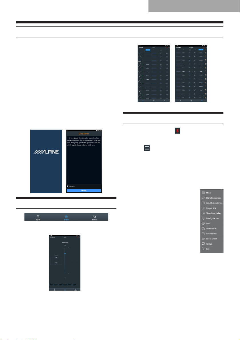
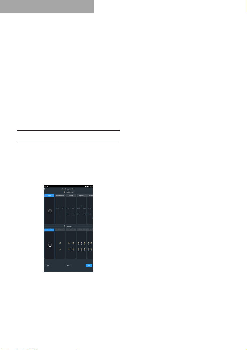
Alpine PXE-X09 User manual

HIGH-RESOLUTION WIRELESS
DIGITAL SOUND PROCESSOR
PXE-X09

Contents
Operation Instructions
Warning......................................................1
Attention .....................................................1
Important Instructions.................................1
Precautions
Function List...............................................2
List of Accessories .....................................2
Introduction to the DSP
1. Connections of the DSP.........................3
2. Introduction to the Connectors and
Functions....................................................4
Mobile Phone App Instructions
Introduction to the Main Interface...............5
Connecting to the DSP...............................5
Setting the Input Mode ...............................6
Setting the Output Mode ............................8
Setting the Crossover...............................10
Setting the Channel EQ ...........................10
Setting the Equalizer ................................11
Setting the Channel Phase and Volume ..11
Setting the Channel Link ..........................11
Setting the Delay......................................12
Sound Effect Presets ...............................12
Setting the Master Volume and Sound
Source......................................................12
Copy and Paste Function.........................12
Software Instructions
Important Instructions for Software
Installation ................................................13
Introduction to the Main Interface.............13
Connecting to the DSP.............................14
Setting the Input Mode .............................15
Setting the Output Mode ..........................17
Setting the Crossover...............................19
Setting the Channel EQ ...........................20
Setting the Equalizer ................................20
Setting the Channel Phase and Volume ..21
Setting the Channel Link ..........................21
Setting the Delay......................................21
Sound Effect Presets ...............................22
Setting the Master Volume and Sound
Source......................................................22
Copy and Paste Function.........................22
Spectral Diagrams of Output Channels....22
Instructions for the Use of the Wired
Controller
Startup Screen .........................................23
Master Volume .........................................23
Main Source .............................................23
Mix Source ...............................................23
Subwoofer Volume (SUBW).....................24
Sound Effect Presets (PRESET)..............24
Technical Parameters
1. Technical specifications........................25
2. Functional parameters .........................26
Information
Harmful Substances.................................27

1
Operation Instructions
Warning
Warning
This symbol is intended to alert you. It may cause
serious injury or death if neglected by you.
Please immediately stop using the
product if any problem occurs.
Please send the product to the designated Alpine
dealers or nearby Alpine service centers for
repairing.
Do not use any functions that may divert
your attention when driving.
Only use such functions that distract you when
the car stops. Make sure that you park your
car in a safe place before using such functions.
Otherwise, it may cause accidents.
Keep the audio volume to a level that
will not block out outside trafc noises.
It’s dangerous or may cause accidents, if the
audio volume is too loud to hear the sirens of
emergency vehicles or road sirens (e.g. at the
intersection of railway line). In addition, loud
sound may hurt your hearing.
Do not disassemble or modify the product.
Otherwise, it may cause accidents, re or electric
shock.
Keep children away from small parts,
such as bolts and screws.
Swallowing them may result in serious injury.
In case of swallow, please consult a physician
immediately.
This product only applies to 12 V -type
vehicles.
Otherwise, it may cause re, electric shock or
other injury.
Attention
This symbol is intended to alert you. It may
cause injury or damage devices if you don’t
pay attention.
Important Instructions
Product Cleaning
Please clean the product by a dry soft cloth
regularly. Clean the product only with a soft cloth
dampened with water, if the dirt is not easily
removed. Other solvents may be soluble.
Temperature
Please ensure the in-vehicle temperature
between +60°C and -20°C before use.
Maintenance
Should you meet any problems, please do not
attempt to undertake repairs yourself. Please
send the product to Alpine dealers or nearby
Alpine service centers for repairing.
Installation Location
Do not install PXE-X09 in the following places:
●Under the direct Sunlight or near heating
sources
●A very humid place or near water source
●Dusty place
●A place of violent vibration
Attention
Alpine is not liable for any documents loss,
including lost documents when using this
product.
BLUETOOTH®word mark and logos are
registered trademarks owned by Bluetooth SIG,
Inc.
Alpine Electronics, Inc. has been authorized to
use them.

2
Precautions
You can use PXE-X09 mobile phone app or PC software to tune and set up the PXE-X09. The control
with the two methods differs slightly and thus will be discussed in different chapters. The function list
is as follows:
Function List
Item Page
Mobile Phone PC
Basic Operations
Introduction to the Main Interface 5 12
Connecting the DSP 5 13
Setting the Input Mode 6 14
Setting the Output Mode 8 15
Channel
Operation
Setting the Crossover 9 17
Setting the Channel EQ 9 18
Setting the Equalizer 10 18
Setting the Channel Phase and Volume 10 19
Setting the Channel Link 10 19
Setting the Delay 11 19
Sound Effect Presets 11 20
Note: Operations on PC are only available to dealers and the manufacturer.
List of Accessories
The packing shall include the following accessories; if any of them is missing, please contact your dealer
or the manufacturer as soon as possible.
Accessories Quantity
Bluetooth module ×1
Fixing support ×4
Power cable ×1
Wired Controller ×1
PCA connector ×16
USB 3.0 cable ×1
Bluetooth module 1 (set)
Wired Controller 1 (set)
Fixing support 4 (pcs)
PCA connector 16 (pcs)
Power cable 1 (pc)
USB 3.0 cable 1 (pc)
Truss head screw 4 (pcs)
Round head screw 8 (pcs)
Manual 1

3
Introduction to the DSP
1. Connections

4
2. Introduction to the Connectors and Functions
1Power Connector
+12V REM OUT ACC GND
2Input selection switch
When the switch is turned to “ACC”, the DSP will be started by ACC; when the switch is turned
to “HOST”, the DSP will be started by high level input signal IN-1.
345678910 High and low level mixed input Connectors
The high or low level inputs can be set through the wired controller, PC or mobile phone app.
When it is set to the high level, it can be connected with the high level output (speakers) of in-
car CD or DVD players; when it is set to low level, it can be connected with the low level output
(audio signals) of in-car CD or DVD players to play low level signals.
11 8 groups of low-level input indicators
When the high and low level mixed input connector is set to high level input, the LED indicator
of the corresponding connection is on; when it is set to low level input, the LED indicator of the
corresponding connection is off.
12 13 Optical and Coaxial Connections
When the optical or coaxial input cable of in-car CD or DVD player is connected, the sound
source of the DSP is switched to digital input, and optical or coaxial digital signals can be
played. Note: Please use coaxial cables with the impedance of 75Ω.
14 External Bluetooth interface
Lossless music can be played through Bluetooth connection. Start the PXE-X09 mobile phone
app and turn the Bluetooth of your mobile phone; the Bluetooth indicator is on.
15 USB 3.0 Connection
You can use a USB 3.0 cable to connect with PC or the wired controller to adjust the volume,
select sound source and load data.
16 17 18 19 20 21 22 23 Low level output connections
8 groups of low level outputs that can be connected to the external power amplier.
24 Car CD or DVD player
25 External power amplier

5
Mobile Phone App
Mobile Phone App Instructions
For iPhone users, search and download PXE-X09
Tuning App from App Store; for Android users,
please scan the QR code on the cover, download
and installed the app.
After the PXE-X09 app is installed, start PXE-X09.
Open “Settings” → “Turn on Bluetooth” → “Search
Devices” → “DSP-HD-...” from your mobile phone
and click to connect. Or directly start the app
to search Bluetooth automatically, and click to
connect “DSP-HD-...”; when it progresses to 100%,
the connection is established successfully.
Then start the PXE-X09 app on your phone, it will
connect to the DSP automatically. It will enter
the Alpine startup page. Read the Disclaimer
carefully and then click “Accept” to enter the
main interface.
Introduction to the Main Interface
There are 3 control interfaces: Input, Home and
Output. The default page is Home.
Home interface
Input interface Output interface
Connecting to the DSP
1. If the Bluetooth icon “ ” is red, it indicates
the Bluetooth is not connected; if it is green,
it indicates that the Bluetooth is connected.
2. Click “ ” to enter “Mixer”, “Signal
generator”, “Input link settings”, “Output link”,
“Shutdown delay”, “Conguration wizard”,
“Lock”, “Share effect”, “Save effect”, “Local
effect”, “About”, and “Exit”.
a. Select “Mixer” to enter the mixer setting
interface. You can adjust the volume of
each sound source of channels to carry
out the mixing.
b. Select “Signal generator”
to test output signals when
no music is played. When
“Generator output” is selected
for the output signal, pink
noise, white noise, sinusoid
and sinusoid (positive half-
cycle) occur. Volume range:
-60 dB-0 dB; frequency
range: 20 Hz-20 kHz. When
music is selected, the music
will be played. Music output
is set by default.
c. Select “Input link settings” to set the
function to be tuned. There are ve
options: Channel EQ, X-Over, Channel
phase, Channel volume, and Channel
mute.
d. Select “Output link settings” to set the
function to be tuned. There are six
options: Channel EQ, X-Over, Channel
delay, Channel phase, Channel volume,
and Channel mute.

6
e. Select “Shutdown delay” to set the
shutdown delay. The range of the
shutdown delay: 0-255s.
f. Select “Conguration wizard” to enter the
wizard for conguring the main sound
source, input mode, and output mode.
g. Select “Lock” to enter a 6-digit password
to encrypt the tuned sound effect data.
Click “Unlock” to enter the correct
password to decrypt the locked data.
The initial password is “888888”.
h. Select “Share effect” to share a sound
effect or all sound effects.
i. Select “Save effect” to enter the le
name and notes and save a sound effect
or all sound effects.
j. Select “Local effect” to load the sound
effect les stored on your phone.
k. Select “About” to check the device version.
l. Select “Exit” to close the app.
Setting the Input Mode
Click “Input mode” to enter the high level and low
level input setting interface. Select the high level
or low level input mode by moving the slider left
or right. Click “Clear all” to enter the customization
operation interface.
Note: the “Clear all” button is invalid in the
customized setting interface.
1. High level input selection:
(1) Front Sound Field Stereo (2CH):
Front Left and Front Right channels of
IN 1 and 2 are set to Full-range.
(2) Four-CH (4CH):
Front Left and Front Right channels of
IN 1 and 2 are set to Full-range;
Rear Left and Rear Right channels of
IN 3 and 4 are set to Full-range.
Mobile Phone App
(3) Four-CH + FC (5CH):
Front Left and Front Right channels of
IN 1 and 2 are set to Full-range;
Rear Left and Rear Right channels of
IN 3 and 4 are set to Full-range;
IN 5 is set to Subwoofer.
(4) Four-CH + Left and Right FC (6CH):
Front Left and Front Right channels of
IN 1 and 2 are set to Full-range;
Rear Left and Rear Right channels of
IN 3 and 4 are set to Full-range;
Left and Right channels of IN 5 and 6
are set to Subwoofer.
(5) Two Front Channels + Rear Channels
(6CH):
Front Left and Front Right channels of
IN 1 and 2 are set to Tweeter;
Front Left and Front Right channels of
IN 3 and 4 are set to Mid-bass;
Rear Left and Rear Right channels of
IN 5 and 6 are set to Full-range.
(6) Two Front Channels + Rear
Channels + FC (7CH):
Front Left and Front Right channels of
IN 1 and 2 are set to Tweeter;
Front Left and Front Right channels of
IN 3 and 4 are set to Mid-bass;
Rear Left and Rear Right channels of
IN 5 and 6 are set to Full-range;
IN 7 is set to Subwoofer.
(7) Two Front Channels + Rear
Channels + Left and Right FC (8CH):
Front Left and Front Right channels of
IN 1 and 2 are set to Tweeter;
Front Left and Front Right channels of
IN 3 and 4 are set to Mid-bass;
Rear Left and Rear Right channels of
IN 5 and 6 are set to Full-range;
Left and Right channels of IN 7 and 8
are set to Subwoofer.
(8) Two Front Channels + Rear
Channels + Center Channel + Left
and Right FC (9CH):
Front Left and Front Right channels of
IN 1 and 2 are set to Tweeter;
Front Left and Front Right channels of
IN 3 and 4 are set to Mid-bass;
Rear Left and Rear Right channels of
IN 5 and 6 are set to Full-range;
Left and Right channels of IN 7 and 8
are set to Subwoofer;
IN 9 is the center channel and set to
Full-range.
(9) Two Front Channels + Rear Channels +
Center Channel + FC (8CH):
Front Left and Front Right channels of
IN 1 and 2 are set to Tweeter;

7
Mobile Phone App
Front Left and Front Right channels of
IN 3 and 4 are set to Mid-bass;
Rear Left and Rear Right channels of
IN 5 and 6 are set to Full-range;
IN 7 is the center channel and set to
Full-range;
In 8 is set to Subwoofer.
(10) Three Front Channels + Two Rear
Channels + Center Channel + FC
(12CH):
Front Left and Front Right channels of
IN 1 and 2 are set to Tweeter;
Front Left and Front Right channels of
IN 3 and 4 are set to Midrange;
Front Left and Front Right channels of
IN 5 and 6 are set to Woofer;
Rear Left and Rear Right channels of
IN 7 and 8 are set to Tweeter;
Rear Left and Rear Right channels of
IN 9 and 10 are set to Woofer;
IN 11 is the center channel and set to
Full-range;
IN 12 is set to Subwoofer.
(11) Three Front Channels + Two Rear
Channels + Center Channel + Left
and Right FC (13CH):
Front Left and Front Right channels of
IN 1 and 2 are set to Tweeter;
Front Left and Front Right channels of
IN 3 and 4 are set to Midrange;
Front Left and Front Right channels of
IN 5 and 6 are set to Woofer;
Rear Left and Rear Right channels of
IN 7 and 8 are set to Tweeter;
Rear Left and Rear Right channels of
IN 9 and 10 are set to Woofer;
Left and Right channels of IN 11 and 12
are set to Subwoofer;
IN 13 is the center channel and set to
Full-range.
(12) Three Front Channels + Rear
Channels + Center Channel + FC
(10CH):
Front Left and Front Right channels of
IN 1 and 2 are set to Tweeter;
Front Left and Front Right channels of
IN 3 and 4 are set to Midrange;
Front Left and Front Right channels of
IN 5 and 6 are set to Woofer;
Rear Left and Rear Right channels of
IN 7 and 8 are set to Full-range;
IN 9 is the center channel and set to
Full-range;
IN 10 is set to Subwoofer.
(13) Three Front Channels + Two Rear
Channels + Center Channel + Left
and Right FC (11CH):
Front Left and Front Right channels of
IN 1 and 2 are set to Tweeter;
Front Left and Front Right channels of
IN 3 and 4 are set to Midrange;
Front Left and Front Right channels of
IN 5 and 6 are set to Woofer;
Rear Left and Rear Right channels of
IN 7 and 8 are set to Full-range;
Rear Left and Rear Right channels of
IN 9 and 10 are set to Subwoofer;
IN 11 is the center channel and set to
Full-range.
(14) Three Front Channels + Rear
Channels + FC (9CH):
Front Left and Front Right channels of
IN 1 and 2 are set to Tweeter;
Front Left and Front Right channels of
IN 3 and 4 are set to Midrange;
Front Left and Front Right channels of
IN 5 and 6 are set to Woofer;
Rear Left and Rear Right channels of
IN 7 and 8 are set to Full-range;
IN 9 is set to Subwoofer.
(15) Three Front Channels + Rear
Channels + Left and Right FC (10CH):
Front Left and Front Right channels of
IN 1 and 2 are set to Tweeter;
Front Left and Front Right channels of
IN 3 and 4 are set to Midrange;
Front Left and Front Right channels of
IN 5 and 6 are set to Woofer;
Rear Left and Rear Right channels of
IN 7 and 8 are set to Full-range;
Left and Right channels of IN 9 and 10
are set to Subwoofer.
(16) Three Front Channels + Three Rear
Channels + Center Channel High/Low
+ Left and Right FC (16CH):
Front Left and Front Right channels of
IN 1 and 2 are set to Tweeter;
Front Left and Front Right channels of
IN 3 and 4 are set to Midrange;
Front Left and Front Right channels of
IN 5 and 6 are set to Woofer;
Rear Left and Rear Right channels of
IN 7 and 8 are set to Tweeter;
Rear Left and Rear Right channels of
IN 9 and 10 are set to Midrange;
Rear Left and Rear Right channels of
IN 11 and 12 are set to Woofer;
IN 13 is the center channel and set to
Tweeter;
IN 14 is the center channel and set to
Woofer;
Left and Right channels of IN 15 and 16
are set to Subwoofer.

8
Mobile Phone App
2. Low level input selection:
(1) Stereo (2CH):
Front Left and Front Right channels of
IN 1 and 2 are set to Full-range.
(2) Four-CH (4CH):
Front Left and Front Right channels of
IN 1 and 2 are set to Full-range;
Rear Left and Rear Right channels of
IN 3 and 4 are set to Full-range.
(3) Six-CH (5.1CH):
Front Left and Front Right channels of
IN 1 and 2 are set to Full-range;
Rear Left and Rear Right channels of
IN 3 and 4 are set to Full-range;
IN 5 is the center channel and is set to
Full-range
IN 6 is set to Subwoofer.
(4) Eight-CH (7.1CH):
Front Left and Front Right channels of
IN 1 and 2 are set to Full-range;
Rear Left and Rear Right channels of
IN 3 and 4 are set to Full-range;
IN 5 is the center channel and is set to
Full-range;
IN 6 is set to Subwoofer;
IN 7 and 8 are left and right surround.
3. Customization of high level and low level
The sum of the number of high level
channels and the number of low level
channels should not be greater than 16.
(1) Shift between high and low level inputs:
Click “HI” or “AUX” to shift between high
level and low level inputs (the green
triangle symbol indicates the input mode
is the main sound source).
(2) Input mode selection: Click “ ”
and select the input channel type from
the popup dialog box by moving the
slider up and down. For front channels,
options include Tweeter, Midrange,
Woofer, Mid-tweeter, Mid-bass, and
Full-range; for rear channels, options
include Tweeter, Midrange, Woofer,
and Full-range; FC options include left
subwoofer and right subwoofer, and
subwoofer; surround options include left
and right surround.
Setting the Output Mode
Click “Output Mode” to enter the output mode
setting interface. Select the output mode by moving
the slider left and right. Click “Clear all” to enter the
customization operation interface.
Note: the “Clear all” button is invalid in the
customized setting interface.
1. Front Sound Field Stereo (2CH):
Front Left and Front Right channels of OUT
1 and 2 are set to Full-range.
2. Four-CH (4CH):
Front Left and Front Right channels of OUT
1 and 2 are set to Full-range;
Rear Left and Rear Right channels of OUT 3
and 4 are set to Full-range.
3. Four-CH + FC (5CH):
Front Left and Front Right channels of OUT
1 and 2 are set to Full-range;
Rear Left and Rear Right channels of OUT 3
and 4 are set to Full-range;
OUT 5 is set to Subwoofer.

9
Mobile Phone App
4. Four-CH + Left and Right (6CH):
Front Left and Front Right channels of OUT
1 and 2 are set to Full-range;
Rear Left and Rear Right channels of OUT 3
and 4 are set to Full-range;
Left and Right channels of OUT 5 and 6 are
set to Subwoofer.
5. Two Front Channels + Rear Channels
(6CH):
Front Left and Front Right channels of OUT
1 and 2 are set to Tweeter;
Front Left and Front Right channels of OUT
3 and 4 are set to Mid-bass;
Rear Left and Rear Right channels of OUT 5
and 6 are set to Full-range.
6. Two Front Channels + Rear Channels +
FC (7CH):
Front Left and Front Right channels of OUT
1 and 2 are set to Tweeter;
Front Left and Front Right channels of OUT
3 and 4 are set to Mid-bass;
Rear Left and Rear Right channels of OUT 5
and 6 are set to Full-range;
OUT 7 is set to Subwoofer.
7. Two Front Channels + Rear Channels +
Left and Right FC (8CH):
Front Left and Front Right channels of OUT
1 and 2 are set to Tweeter;
Front Left and Front Right channels of OUT
3 and 4 are set to Mid-bass;
Rear Left and Rear Right channels of OUT 5
and 6 are set to Full-range;
Left and Right channels of OUT 7 and 8 are
set to Subwoofer.
8. Two Front Channels + Rear Channels +
Center Channel + Left and Right FC (9CH):
Front Left and Front Right channels of OUT
1 and 2 are set to Tweeter;
Front Left and Front Right channels of OUT
4 and 4 are set to Mid-bass;
Rear Left and Rear Right channels of OUT 5
and 6 are set to Full-range;
Left and Right channels of OUT 7 and 8 are
set to Subwoofer;
OUT 9 is the center channel and set to Full-
range.
9. Two Front Channels + Rear Channels +
Center Channel + FC (8CH):
Front Left and Front Right channels of OUT
1 and 2 are set to Tweeter;
Front Left and Front Right channels of OUT
3 and 4 are set to Mid-bass;
Rear Left and Rear Right channels of OUT 5
and 6 are set to Full-range;
OUT 7 is the center channel and set to Full-
range;
OUT 8 is set to Subwoofer.
10. Three Front Channels + Two Rear
Channels + Center Channel + FC (12CH):
Front Left and Front Right channels of OUT
1 and 2 are set to Tweeter;
Front Left and Front Right channels of OUT
3 and 4 are set to Midrange;
Front Left and Front Right channels of OUT
5 and 6 are set to Woofer;
Rear Left and Rear Right channels of OUT 7
and 8 are set to Tweeter;
Rear Left and Rear Right channels of OUT 9
and 10 are set to Woofer;
OUT 11 is the center channel and set to
Full-range;
OUT 12 is set to Subwoofer.
11. Three Front Channels + Two Rear
Channels + Center Channel + Left and
Right FC (13CH):
Front Left and Front Right channels of OUT
1 and 2 are set to Tweeter;
Front Left and Front Right channels of OUT
3 and 4 are set to Midrange;
Front Left and Front Right channels of OUT
5 and 6 are set to Woofer;
Rear Left and Rear Right channels of OUT 7
and 8 are set to Tweeter;
Rear Left and Rear Right channels of OUT 9
and 10 are set to Woofer;
Left and Right channels of OUT 11 and 12
are set to Subwoofer;
OUT 13 is the center channel and set to
Full-range.
12. Three Front Channels + Rear Channels +
Center Channel + FC (10CH):
Front Left and Front Right channels of OUT
1 and 2 are set to Tweeter;
Front Left and Front Right channels of OUT
3 and 4 are set to Midrange;
Front Left and Front Right channels of OUT
5 and 6 are set to Woofer;
Rear Left and Rear Right channels of OUT 7
and 8 are set to Full-range;
OUT 9 is the center channel and set to Full-
range;
OUT 10 is set to Subwoofer.
13. Three Front Channels + Two Rear
Channels + Center Channel + Left and
Right FC (11CH):
Front Left and Front Right channels of OUT
1 and 2 are set to Tweeter;
Front Left and Front Right channels of OUT
3 and 4 are set to Midrange;
Front Left and Front Right channels of OUT
5 and 6 are set to Woofer;
Rear Left and Rear Right channels of OUT 7
and 8 are set to Full-range;

10
Mobile Phone App
Rear Left and Rear Right channels of OUT 9
and 10 are set to Subwoofer;
OUT 11 is the center channel and set to
Full-range.
14. Three Front Channels + Rear Channels +
FC (9CH):
Front Left and Front Right channels of OUT
1 and 2 are set to Tweeter;
Front Left and Front Right channels of OUT
3 and 4 are set to Midrange;
Front Left and Front Right channels of OUT
5 and 6 are set to Woofer;
Rear Left and Rear Right channels of OUT 7
and 8 are set to Full-range;
OUT 9 is set to Subwoofer.
15. Three Front Channels + Rear Channels +
Left and Right FC (10CH):
Front Left and Front Right channels of OUT
1 and 2 are set to Tweeter;
Front Left and Front Right channels of OUT
3 and 4 are set to Midrange;
Front Left and Front Right channels of OUT
5 and 6 are set to Woofer;
Rear Left and Rear Right channels of OUT 7
and 8 are set to Full-range;
Left and Right channels of OUT 9 and 10 are
set to Subwoofer.
16. Three Front Channels + Three Rear
Channels + Center Channel High/Low +
Left and Right FC (16CH):
Front Left and Front Right channels of OUT
1 and 2 are set to Tweeter;
Front Left and Front Right channels of OUT
3 and 4 are set to Midrange;
Front Left and Front Right channels of OUT
5 and 6 are set to Woofer;
Rear Left and Rear Right channels of OUT 7
and 8 are set to Tweeter;
Rear Left and Rear Right channels of OUT 9
and 10 are set to Midrange;
Rear Left and Rear Right channels of OUT
11 and 12 are set to Woofer;
OUT 13 is the center channel and set to
Tweeter;
OUT 14 is the center channel and set to
Woofer;
Left and Right channels of OUT 15 and 16
are set to Subwoofer.
17. Customized output mode:
Select the number of channels to be set
(1-16).
Click “ ” to set the output channel in
the popup dialog box by moving the slider
up and down. For front channels, options
include Tweeter, Midrange, Woofer, Mid-
tweeter, Mid-bass, and Full-range; for rear
channels, options include Tweeter, Midrange,
Woofer, and Full-range; FC options include
left subwoofer and right subwoofer, and
subwoofer; surround options include left and
right surround.
Setting the Crossover
Click the icon “ ” under EQ to enter the EQ
edit and Crossover setting window. The crossover
tuning area provides tuning of Tweeter and woofer
channels.
1. Mode setting: Linkwitz-Riley, Bessel and
Butterworth.
2. Frequency setting: Move the slider left and
right or press “+” / “-” to set the frequency.
Adjustment range: 20 Hz-20000 Hz.
3. Slope setting: Options include 6 dB/Oct, 12
dB/Oct, 18 dB/Oct, 24 dB/Oct, 30 dB/Oct, 36
dB/Oct, 42 dB/Oct, and 48 dB/Oct.
Note: When the slope is set to 6 dB/Oct, the
type displays “Null”.
Setting the Channel EQ
1. Input EQ edit area
The input EQ has two interfaces: Graphic EQ
and Parameter EQ.
P.EQ interface G.EQ interface

11
Mobile Phone App
There are 10 input EQ values. Move the slider up
and down or click a gain value to display the gain
adjustment box and then move the slider left and
right or press “+”/“-” to set the gain; click a Q value
to display the Q value adjustment box and then
move the slider left and right or press “+”/“-” to set
the Q value; click a frequency value to display the
frequency adjustment box and then move the slider
left and right or press “+”/“-” to set the frequency.
Frequency range: 20 Hz-20 kHz;
Q value range: 0.404-28.852;
Gain range: -12 dB-+12 dB.
Note: In the Graphic EQ interface, the gain
is adjustable, while the frequency and the Q
value cannot be adjusted; in the Parameter
EQ interface, the frequency, Q value and gain
can be adjusted.
2. Output EQ edit area
The output EQ has two interfaces: Graphic
EQ and Parameter EQ.
P.EQ interface G.EQ interface
There are 31 output EQ values. The adjustment
method and range of the frequency, Q value and
gain are similar to the adjustment of the input EQ.
Setting the Equalizer
1. When the EQ is being adjusted, the Direct
EQ button appears.
2. Direct EQ: When the channel EQ is enabled,
the button appears. Click “Direct
EQ” disable all the equalizers of the current
channel.
3. Click “Yes”, and the button will then change
to “Reset EQ” . Click “Reset EQ”,
and all the equalizers of the current channel
will be reset to the previous state. Note: The
state enabled by clicking “Direct EQ” can
be reset by clicking “Reset EQ”, while
the state enabled by clicking the circle
cannot be reset by clicking “Reset EQ”.
4. Click “Reset EQ” , all the equalizers
of the current channel are reset to the initial
state: the input Q value is 2.515, the output
Q value is 2.201, and the gain is 0.0 dB.
5. Click P.EQ to shift to G.EQ. In the P.EQ
mode, the frequency, Q value, and gain can
be adjusted, while in the G.EQ mode, the
frequency and Q value are xed and only the
gain of the EQ can be adjusted.
Setting the Channel Phase and
Volume
Click “ ” under the volume to set the channel
volume or shift the channel phase in the popup
dialog box.
1. Phase: Click the positive phase icon “
” or the negative phase icon “ ” to switch
between the positive and negative phases.
2. Volume: Move the slider or click “+” / “-”
to adjust the volume; the volume range:
-60 dB–6 dB).
3. Mute: Click the volume icon “ ” to mute the
channel “ ”.
Setting the Channel Link
Set the input or output functions to be tuned in
the interface;
Click “ ” to select the channel for link setting
from the popup dialog box. Then the link icon next
to the channel will be green “ ”, indicating the
link setting is enabled.

12
Setting the Delay
Click the delay button “ ” to set the output
signal delay.
1. Delay unit: ms, cm, in;
Delay range: 0.000-20.000 ms;
0-692 cm;
0-273 in.
2. Click the icon to display the delay setting
box, and then move the slider left and right
or press “+”/“-” to set the delay.
Sound Effect Presets
The DSP provides a storage space for 6 groups of
sound effect presets for storing and loading sound
effect data. Move the slider left and right to select
a sound effect preset.
Setting the Master Volume and
Sound Source
Master volume adjustment, sound source
selection, and output signal display section.
1. Adjusting the master volume: Adjust the
volume by either dragging the
volume slider, or by pressing
“+”/“-”, from 0 to 35. The
volume is set at 27 by default.
2. Mute button: Click the “ ”
button to set the main volume
to mute “ ” or click it again
to unmute (adjusting the
master volume will unmute it
automatically).
3. Main sound source selection:
Click the buttons under the main sound
source and select the source from the popup
window. Select the main sound source
from the popup window: Optical, Coaxial,
Bluetooth, High Level, and Low Level.
4. Auxiliary sound source selection: Auxiliary
sound sources are mixed in a similar fashion.
(1) The higher the attenuation of the main
sound source, the lower the master
volume. The available values are: 30%,
50%, 80%, 100%, and Off.
(2) Click the keys under the auxiliary
sound source and select from the
popup window. Options include Optical,
Coaxial, Bluetooth, High Level, Low
Level, and Off.
Note: When a sound source is selected,
it cannot then be selected again
as the auxiliary sound source;
doing so causes the auxiliary
sound source to be invalid.
Optical and Coaxial cannot be
selected at the same time.
Copy and Paste Function
Click the input or output channel area to display
the Copy box; select a channel to be copied and
then press “Conrm” to copy the EQ, volume, and
mute settings of the channel.
Mobile Phone App

13
Software Instructions
Important Instructions for Software Installation
●The software can only run on Microsoft® Windows® platforms.
Recommended specications
Operating system: Windows XP, Windows Vista, Windows 7, Windows 8, Windows 10
CPU: 1.6 GHz or higher
Memory: 1 GB or higher
Hard disk: 512 MB or more
PC resolution: 1280*768 or higher
●Before connecting PXE-X09 to PC, please install the PXE-X09 software correctly.
Introduction to the Main Interface
Start the PXE-X09 software and enter the startup interface, as shown in Figure 1. Select the main
sound source, high and low level input and output modes, or skip to the volume adjustment interface,
as shown in Figure 2.
Figure 1
Software for PC

14
Connecting to the DSP
1. Before the DSP is connected, the
connection icon is in red “ ”; after it is
connected, the connection icon is in green
“ ”.
2. Menu area: File, Option and Lock
(1) Click “File”:
a. Select “Load PC Presets File”: load the
preset le previously saved on your PC
as the current working scenario of the
DSP;
b. Select “Save as PC Presets File”: Save
the current working scenario data of the
DSP on your PC for future use;
c. Select “Load All Presets”: Load all data
les previously saved on your PC to the
DSP (all data les of the DSP include
all data, including current working
Figure 2
scenarios, preset scenarios, output
channel conguration data, etc.) to copy
all the data of a DSP that had been well
adjusted to the currently connected
DSP;
d. Select “Save All Presets”: Save all
data les of the connected DSP to your
PC (all data les of the DSP include
all the data, including current working
scenarios, preset scenarios, output
channel conguration data, etc.) for
use on other DSP in the future. This
operation will not alter any data on the
currently connected DSP.
e. Select “Print” to print the current output
conguration as a PDF or edit the
conguration.
(2) Click “Option”:
a. Select “Mixer” to enter the mixer setting
interface. You can adjust the volume of
each sound source of channels to carry
out the mixing.
b. Select “Signal generator” to test output
signals when no music is played. When
“Generator output” is selected for the
output signal, pink noise, white noise,
sinusoid and sinusoid (positive half-
cycle) occur. Volume range: -60 dB –
0 dB; frequency range: 20 Hz – 20 kHz.
Music output is set by default.
Software for PC

15
c. Select “Input link settings” to set the
function to be tuned. There are ve
options: Channel EQ, X-Over, Channel
phase, Channel volume, and Channel
mute.
d. Select “Output link settings” to set the
function to be tuned. There are six
options: Channel EQ, X-Over, Channel
delay, Channel phase, Channel, volume
and Channel mute.
e. Select “Advanced” to turn the ow lamp
on or off. The range of the shutoff delay:
0 - 255s.
f. Select “Conguration wizard” to enter
the high level, low level, or output
conguration wizard.
g. Select “Firmware update”, select the
update le from the popup dialog box,
and then click “Update” to update the
rmware. When the update progress
reaches 100%, it means the rmware
is updated successfully. Click “Conrm”
to exit the rmware update. After the
update, the DSP will be restarted
automatically.
h. Select “Restore factory settings”. All the
settings of the DSP will be reset to the
factory defaults.
i. Select “Language” to switch between
Chinese and English.
j. Select “About” to check the device
version.
(3) Click “Lock”:
Enter a 6-digit password in the popup
dialog box to encrypt the tuned sound
effect data. You can encrypt the EQ
frequency, Q value and gain value
data. The tuning data as delay time,
channel, and phase equalizer settings
will also be encrypted. The encryption
is only effective for the sound effect
data currently used, instead of all the
data of the DSP. The encrypted sound
effect data can be saved as the preset
sound effects or PC les. Copying or
transmission will not decrypt the data.
Click “Unlock” to enter the correct
password to decrypt the locked data.
The initial password is “888888”.
Warning! Please remember your password;
otherwise, the encrypted data cannot be
unlocked.
Setting the Input Mode
Click “Input mode” to enter the high level and low
level input setting interface. Select high or low
level input mode by scrolling your mouse wheel
or dragging the scroll bar. Click “Clear all” to enter
the customization operation interface.
Note: the “Clear all” button is invalid in the
customized setting interface.
1. High level input selection
(1) Front Sound Field Stereo (2CH):
Front Left and Front Right channels of
IN 1 and 2 are set to Full-range.
(2) Four-CH (4CH):
Front Left and Front Right channels of
IN 1 and 2 are set to Full-range;
Rear Left and Rear Right channels of
IN 3 and 4 are set to Full-range.
(3) Four-CH + FC (5CH):
Front Left and Front Right channels of
IN 1 and 2 are set to Full-range;
Rear Left and Rear Right channels of
IN 3 and 4 are set to Full-range;
IN 5 is set to Subwoofer.
Software for PC

16
(4) Four-CH + Left and Right FC (6CH):
Front Left and Front Right channels of
IN 1 and 2 are set to Full-range;
Rear Left and Rear Right channels of
IN 3 and 4 are set to Full-range;
Left and Right channels of IN 5 and 6
are set to Subwoofer.
(5) Two Front Channels + Rear
Channels (6CH):
Front Left and Front Right channels of
IN 1 and 2 are set to Tweeter;
Front Left and Front Right channels of
IN 3 and 4 are set to Mid-bass;
Rear Left and Rear Right channels of
IN 5 and 6 are set to Full-range.
(6) Two Front Channels + Rear
Channels + FC (7CH):
Front Left and Front Right channels of
IN 1 and 2 are set to Tweeter;
Front Left and Front Right channels of
IN 3 and 4 are set to Mid-bass;
Rear Left and Rear Right channels of
IN 5 and 6 are set to Full-range;
IN 7 is set to Subwoofer.
(7) Two Front Channels + Rear
Channels + Left and Right FC (8CH):
Front Left and Front Right channels of
IN 1 and 2 are set to Tweeter;
Front Left and Front Right channels of
IN 3 and 4 are set to Mid-bass;
Rear Left and Rear Right channels of
IN 5 and 6 are set to Full-range;
Left and Right channels of IN 7 and 8
are set to Subwoofer.
(8) Two Front Channels + Rear
Channels + Center Channel + Left
and Right FC (9CH):
Front Left and Front Right channels of
IN 1 and 2 are set to Tweeter;
Front Left and Front Right channels of
IN 3 and 4 are set to Mid-bass;
Rear Left and Rear Right channels of
IN 5 and 6 are set to Full-range;
Left and Right channels of IN 7 and 8
are set to Subwoofer;
IN 9 is the center channel and set to
Full-range.
(9) Two Front Channels + Rear Channels
+ Center Channel + FC (8CH):
Front Left and Front Right channels of
IN 1 and 2 are set to Tweeter;
Front Left and Front Right channels of
IN 3 and 4 are set to Mid-bass;
Rear Left and Rear Right channels of
IN 5 and 6 are set to Full-range;
IN 7 is the center channel and set to
Full-range;
In 8 is set to Subwoofer.
(10) Three Front Channels + Two Rear
Channels + Center Channel + FC
(12CH):
Front Left and Front Right channels of
IN 1 and 2 are set to Tweeter;
Front Left and Front Right channels of
IN 3 and 4 are set to Midrange;
Front Left and Front Right channels of
IN 5 and 6 are set to Woofer;
Rear Left and Rear Right channels of
IN 7 and 8 are set to Tweeter;
Rear Left and Rear Right channels of
IN 9 and 10 are set to Woofer;
IN 11 is the center channel and set to
Full-range;
IN 12 is set to Subwoofer.
(11) Three Front Channels + Two Rear
Channels + Center Channel + Left
and Right FC (13CH):
Front Left and Front Right channels of
IN 1 and 2 are set to Tweeter;
Front Left and Front Right channels of
IN 3 and 4 are set to Midrange;
Front Left and Front Right channels of
IN 5 and 6 are set to Woofer;
Rear Left and Rear Right channels of
IN 7 and 8 are set to Tweeter;
Rear Left and Rear Right channels of
IN 9 and 10 are set to Woofer;
Left and Right channels of IN 11 and 12
are set to Subwoofer;
IN 13 is the center channel and set to
Full-range.
(12) Three Front Channels + Rear
Channels + Center Channel + FC
(10CH):
Front Left and Front Right channels of
IN 1 and 2 are set to Tweeter;
Front Left and Front Right channels of
IN 3 and 4 are set to Midrange;
Front Left and Front Right channels of
IN 5 and 6 are set to Woofer;
Rear Left and Rear Right channels of
IN 7 and 8 are set to Full-range;
IN 9 is the center channel and set to
Full-range;
IN 10 is set to Subwoofer.
(13) Three Front Channels + Two Rear
Channels + Center Channel + Left
and Right FC (11CH):
Front Left and Front Right channels of
IN 1 and 2 are set to Tweeter;
Front Left and Front Right channels of
IN 3 and 4 are set to Midrange;
Front Left and Front Right channels of
IN 5 and 6 are set to Woofer;
Rear Left and Rear Right channels of
IN 7 and 8 are set to Full-range;
Software for PC

17
Rear Left and Rear Right channels of
IN 9 and 10 are set to Subwoofer;
IN 11 is the center channel and set to
Full-range.
(14) Three Front Channels + Rear
Channels + FC (9CH):
Front Left and Front Right channels of
IN 1 and 2 are set to Tweeter;
Front Left and Front Right channels of
IN 3 and 4 are set to Midrange;
Front Left and Front Right channels of
IN 5 and 6 are set to Woofer;
Rear Left and Rear Right channels of
IN 7 and 8 are set to Full-range;
IN 9 is set to Subwoofer.
(15) Three Front Channels + Rear
Channels + Left and Right FC
(10CH):
Front Left and Front Right channels of
IN 1 and 2 are set to Tweeter;
Front Left and Front Right channels of
IN 3 and 4 are set to Midrange;
Front Left and Front Right channels of
IN 5 and 6 are set to Woofer;
Rear Left and Rear Right channels of
IN 7 and 8 are set to Full-range;
Left and Right channels of IN 9 and 10
are set to Subwoofer.
(16) Three Front Channels + Three Rear
Channels + Center Channel High/
Low + Left and Right FC (16CH):
Front Left and Front Right channels of
IN 1 and 2 are set to Tweeter;
Front Left and Front Right channels of
IN 3 and 4 are set to Midrange;
Front Left and Front Right channels of
IN 5 and 6 are set to Woofer;
Rear Left and Rear Right channels of
IN 7 and 8 are set to Tweeter;
Rear Left and Rear Right channels of
IN 9 and 10 are set to Midrange;
Rear Left and Rear Right channels of
IN 11 and 12 are set to Woofer;
IN 13 is the center channel and set to
Tweeter;
IN 14 is the center channel and set to
Woofer;
Left and Right channels of IN 15 and
16 are set to Subwoofer.
2. Low level input selection
(1) Stereo (2CH):
Front Left and Front Right channels of
IN 1 and 2 are set to Full-range.
(2) Four-CH (4CH):
Front Left and Front Right channels of
IN 1 and 2 are set to Full-range;
Rear Left and Rear Right channels of
IN 3 and 4 are set to Full-range.
(3) Six-CH (5.1CH):
Front Left and Front Right channels of
IN 1 and 2 are set to Full-range;
Rear Left and Rear Right channels of
IN 3 and 4 are set to Full-range;
IN 5 is the center channel and is set to
Full-range
IN 6 is set to Subwoofer.
(4) Eight-CH (7.1CH):
Front Left and Front Right channels of
IN 1 and 2 are set to Full-range;
Rear Left and Rear Right channels of
IN 3 and 4 are set to Full-range;
IN 5 is the center channel and is set to
Full-range;
IN 6 is set to Subwoofer;
IN 7 and 8 are left and right surround.
3. Customization of high level and low level
The sum of the number of high level
channels and the number of low level
channels should not be greater than 16.
(1) Shift between high and low level inputs: Click
“HI” or “AUX” to shift between high level and low
level inputs (the green triangle symbol indicates
the input mode is the main sound source).
(2) Input mode selection: Click “ ” and set
the input mode in the input mode setting dialog
box. For front channels, options include Tweeter,
Midrange, Woofer, Mid-tweeter,
Mid-bass, and Full-range; for rear
channels, options include
Tweeter, Midrange, Woofer, and
Full-range; FC options include left
subwoofer and right subwoofer,
and subwoofer; surround options
include left and right surround.
Setting the Output Mode
Click “Output Mode” to enter the output mode
setting interface. Select the output mode by
scrolling your mouse wheel or dragging the scroll
bar. Click “Clear all” to enter the customization
operation interface.
Software for PC

18
Note: the “Clear all” button is invalid in the
customized setting interface.
1. Front Sound Field Stereo (2CH):
Front Left and Front Right channels of OUT
1 and 2 are set to Full-range.
2. Four-CH (4CH):
Front Left and Front Right channels of OUT
1 and 2 are set to Full-range;
Rear Left and Rear Right channels of OUT
3 and 4 are set to Full-range.
3. Four-CH + FC (5CH):
Front Left and Front Right channels of OUT
1 and 2 are set to Full-range;
Rear Left and Rear Right channels of OUT
3 and 4 are set to Full-range;
OUT 5 is set to Subwoofer.
4. Four-CH + Left and Right (6CH):
Front Left and Front Right channels of OUT
1 and 2 are set to Full-range;
Rear Left and Rear Right channels of OUT
3 and 4 are set to Full-range;
Left and Right channels of OUT 5 and 6 are
set to Subwoofer.
5. Two Front Channels + Rear Channels
(6CH):
Front Left and Front Right channels of OUT
1 and 2 are set to Tweeter;
Front Left and Front Right channels of OUT
3 and 4 are set to Mid-bass;
Rear Left and Rear Right channels of OUT
5 and 6 are set to Full-range.
6. Two Front Channels + Rear Channels +
FC (7CH):
Front Left and Front Right channels of OUT
1 and 2 are set to Tweeter;
Front Left and Front Right channels of OUT
3 and 4 are set to Mid-bass;
Rear Left and Rear Right channels of OUT
5 and 6 are set to Full-range;
OUT 7 is set to Subwoofer.
7. Two Front Channels + Rear Channels +
Left and Right FC (8CH):
Front Left and Front Right channels of OUT
1 and 2 are set to Tweeter;
Front Left and Front Right channels of OUT
3 and 4 are set to Mid-bass;
Rear Left and Rear Right channels of OUT
5 and 6 are set to Full-range;
Left and Right channels of OUT 7 and 8 are
set to Subwoofer.
8. Two Front Channels + Rear Channels
+ Center Channel + Left and Right FC
(9CH):
Front Left and Front Right channels of OUT
1 and 2 are set to Tweeter;
Front Left and Front Right channels of OUT
4 and 4 are set to Mid-bass;
Rear Left and Rear Right channels of OUT
5 and 6 are set to Full-range;
Left and Right channels of OUT 7 and 8 are
set to Subwoofer;
OUT 9 is the center channel and set to
Full-range.
9. Two Front Channels + Rear Channels +
Center Channel + FC (8CH):
Front Left and Front Right channels of OUT
1 and 2 are set to Tweeter;
Front Left and Front Right channels of OUT
3 and 4 are set to Mid-bass;
Rear Left and Rear Right channels of OUT
5 and 6 are set to Full-range;
OUT 7 is the center channel and set to
Full-range;
OUT 8 is set to Subwoofer.
10. Three Front Channels + Two Rear
Channels + Center Channel + FC (12CH):
Front Left and Front Right channels of OUT
1 and 2 are set to Tweeter;
Front Left and Front Right channels of OUT
3 and 4 are set to Midrange;
Front Left and Front Right channels of OUT
5 and 6 are set to Woofer;
Rear Left and Rear Right channels of OUT
7 and 8 are set to Tweeter;
Rear Left and Rear Right channels of OUT
9 and 10 are set to Woofer;
OUT 11 is the center channel and set to
Full-range;
OUT 12 is set to Subwoofer.
11. Three Front Channels + Two Rear
Channels + Center Channel + Left and
Right FC (13CH):
Front Left and Front Right channels of OUT
1 and 2 are set to Tweeter;
Front Left and Front Right channels of OUT
3 and 4 are set to Midrange;
Software for PC
Other manuals for PXE-X09
1
Table of contents
Other Alpine Recording Equipment manuals

Alpine
Alpine APF-X310MIB User manual

Alpine
Alpine APF-V100GM User manual

Alpine
Alpine 3007 User manual

Alpine
Alpine PXA-H100 User manual

Alpine
Alpine PXE-0850S User manual

Alpine
Alpine PXA-H100 User manual

Alpine
Alpine EZi-DAB-ONE User manual

Alpine
Alpine 3321 User manual

Alpine
Alpine KCE-250BT User manual

Alpine
Alpine PXE-0850X User manual