Magnadyne MobileVision M125C Quick start guide

Model: M125C
For Technical Assistance, please call (800) 638-3600,
or visit www.magnadyne.com
7" Color LCD Monitor
Owner’s/Installation Manual

2
Warning
Backing Up Your Vehicle
Do not backup your vehicle while looking at the monitor. Alwayslook in the direction of your
vehicle’smotion. Use the monitor only asan aid in safety confirmation. The actual distance
may be different than it appearsin the monitor. The range of the image in the monitor islim-
ited. Alwaysbe aware that blind spotsmay exist and not appear at all timeson your monitor.
The product isintended to assist in safe driving and allowsthe driver to have a broader field
of vision during backup. You, asthe driver, are solely responsible for the safe operation of
your vehicle and the safety of your passengersand pedestrians, and for abiding of all state
and local traffic regulations. Do not use any featuresof thissystem to the extent it distracts
you from safe driving. Your first priority while driving should alwaysbe the safe operation
of your vehicle. MobileVision will not accept any responsibility whatsoever for accidents
and/or injuriesresulting from failure to observe these precautionsor safety instructions.
Caution
Introduction
Congratulationson the purchase of a quality MobileVision 7” LCD Monitor. Thissystem hasbeen
designed to provide yearsof trouble free operation.
The information enclosed providesa quick reference of the operationsand maintenance of the
new monitor.
Thisproduct must be installed and used in accordance with thismanual. Any alterationsto this
product that enablesit to be used in any way other than intended or designed could distract the
driver and result in an accident causing injury or death. Magnadyne Corporation disclaimsany
and all liability that may result from failure to install and operate in any other manner in which
thiswasintended.
• FCC REGULATIONS STATE THAT ANY UNAUTHORIZED CHANGES OR MODIFICATIONS TO THIS EQUIP-
MENT MAY VOID THE USER’S AUTHORITY TO OPERATE IT.
• TO REDUCE THE RISK OF FIRE OR ELECTRIC SHOCK, DO NOT EXPOSE THIS EQUIPMENT TO RAIN OR
MOISTURE.
• THIS DEVICE IS INTENDED FOR CONTINUOUS OPERATION.
• TO REDUCE THE RISK OF FIRE OR ELECTRIC SHOCK AND ANNOYING INTERFERENCE, USE ONLY THE
RECOMMENDED ACCESSORIES.
Introduction . . . . . . . . . . . . . . . . . . . . . . . . . . . . . . . . . . . . . . . . . . . . . . . . . . . . . . . . . . . . . . . 2
Warning / Caution . . . . . . . . . . . . . . . . . . . . . . . . . . . . . . . . . . . . . . . . . . . . . . . . . . . . . . . . . . . 2
Monitor Featuresand Controls. . . . . . . . . . . . . . . . . . . . . . . . . . . . . . . . . . . . . . . . . . . . . . . . . 3
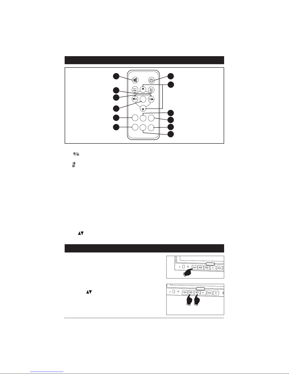
Remote Control Functions. . . . . . . . . . . . . . . . . . . . . . . . . . . . . . . . . . . . . . . . . . . . . . . . . . . . 4
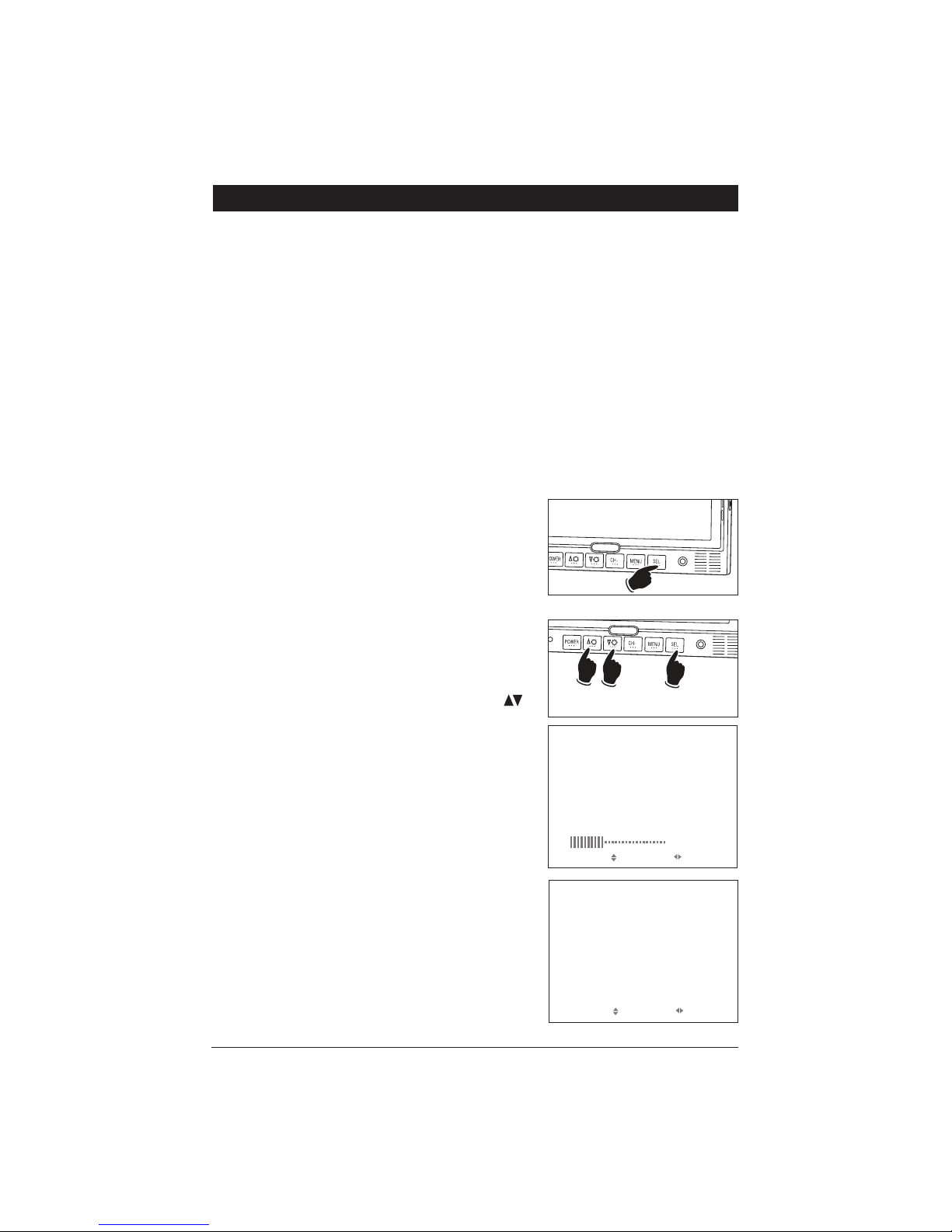
General Operation . . . . . . . . . . . . . . . . . . . . . . . . . . . . . . . . . . . . . . . . . . . . . . . . . . . . . . . . . 4-6
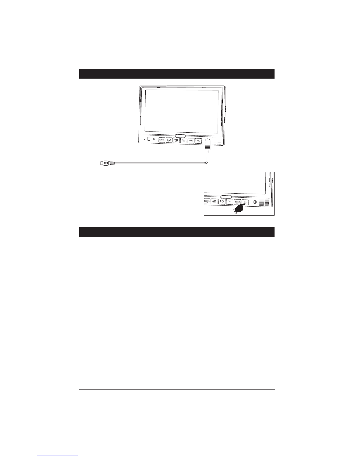
Connection of Video Input Cable and Technical Specs. . . . . . . . . . . . . . . . . . . . . . . . . . . . . . . 7
Wiring Diagram . . . . . . . . . . . . . . . . . . . . . . . . . . . . . . . . . . . . . . . . . . . . . . . . . . . . . . . . . . . . 8
Installation Instructions. . . . . . . . . . . . . . . . . . . . . . . . . . . . . . . . . . . . . . . . . . . . . . . . . . . . 9-10
Maintenance . . . . . . . . . . . . . . . . . . . . . . . . . . . . . . . . . . . . . . . . . . . . . . . . . . . . . . . . . . . . . 11
Trouble Shooting . . . . . . . . . . . . . . . . . . . . . . . . . . . . . . . . . . . . . . . . . . . . . . . . . . . . . . . . . . 11
Warranty . . . . . . . . . . . . . . . . . . . . . . . . . . . . . . . . . . . . . . . . . . . . . . . . . . . . . . . . . . . . . . . . . 12
Table of Contents

3
Monitor Features and Controls
1. LCD Screen
2. IR Sensor: Receivessignal from the
remote control.
3. LED Power Indicator:
A red LED indicatesthe vehicle’signition
is“On” and the monitor isin the “stand-
by” mode. When the vehicle isput into
reverse or the turn signalsare used the
camera’simage will automatically appear
on the display. Note: The camerascan
not be manually selected in thismode.
A green LED indicatesthe power button
on the monitor hasbeen pressed and the
ignition is“On”. The camera’simages
can manually be selected to appear by
using the SEL button. The video in jack
isalso operational.
LED isoff: The monitor hasno function.
4. Power Button: Press thisbutton to turn
the unit "On" or "Off".
Note: The ignition key must be in the
“On” position.
5. Brightness Button (Decrease): Press
thisbutton to decrease the screen’s
brightness.
Note: When the menu isdisplayed press
thisbutton to adjust the selected menu
item.
6. Brightness Button (Increase): Press this
button to increase the screen’sbrightness.
Note: When the menu isdisplayed, press
thisbutton to adjust the selected menu
item.
7. CH- Button (Menu Item Selection):
Press thisbutton to select a menu item
when a menu isdisplayed.
8. Menu Button: Press thisbutton to select
a desired menu screen.
9. SEL: Press thisbutton to select a video
sources(CAM1, CAM2, CAM3 and DVD).
Note 1: When the left turn signal isacti-
vated CAM1 (left side view camera) is
selected automatically.
Note 2: When the right turn signal is
activated CAM2 (right side view camera)
isselected automatically.
Note 3: When the vehicle isput into
reverse CAM3 (rearview camera) is
selected automatically.
10. Video Input Jack
11. Speaker: The speaker isautomatically
activated only when the vehicle isput
into reverse.
Note: The rear camera must have a built-
in microphone for proper operation.
21 4789
310 11
5 6

Remote Control Functions
1. Mute: Push to "Mute" the volume.
2. : Press thisbutton to select between
a Mirror or Normal screen image.
: Press thisbutton to flip the screen
image vertically.
3. POWER: Press thisbutton to turn the
unit "On" or "Off".
4. MENU: Press thisbutton to select a
desired menu.
5. MODE (Picture Mode):Press to select
between Personal, Standard, Soft, Vivid
and Light picture settings.
6. LANG (Language Mode):Press to select
display language.
7. POWER: Press thisbutton to turn the
unit "On" or "Off".
8. CH : Press these buttonsto scroll
through a menu Up or Down.
9. CALL: Press to close the menu.
10. TIMER: Press to select the shut off time.
When the timer expiresthe monitor will
automatically shut off.
11. SEL: Press thisbutton to select a video
sources(CAM1, CAM2, CAM3 and DVD).
Note 1: When the left turn signal isacti-
vated CAM1 (left side view camera) is
selected automatically.
Note 2: When the right turn signal is
activated CAM2 (right side view camera)
isselected automatically.
Note 3: When the vehicle isput into
reverse CAM3 (rearview camera) is
selected automatically.
12. SYS: Press to select PAL, AUTO, N443
or N358.
MUTE POWER
MODE CALL
17
8
9
10
11
12
CH
MENU
CH
TIMER
LANG SYS
SEL
2
3
4
5
6
4
General Operation
Turning the Monitor On:
The monitor isoperational by activating the ignition
key then manually pressing the power switch on the
unit.
Adjusting the Brightness
Press the buttonson the monitor to adjust the
brightness of the monitor.
Brightness
Up
Brightness
Down

General Operation
Camera View Selection and A/V Input:
Left Side Camera:
The left side view camera (CAM1) isdesigned to
automatically turn on whenever the vehicle’sleft turn
signal isactivated.
Right Side Camera:
The right side view camera (CAM2) isdesigned to
automatically turn on whenever the vehicle’sright
turn signal isactivated.
Rearview Camera:
The rearview camera (CAM3) isdesigned to auto-
matically turn on whenever the vehicle isplaced into
reverse gear.
Video Input:
Manually select the video input by pressing the SEL
button on the monitor until DVD appearsin the display.
Note: Select any camera view manually by pressing
the SEL button on the monitor. If a camera view is
automatically activated (Example: the vehicle isin
reverse) you will not be able to manually select a dif-
ferent camera view until the vehicle taken out of
reverse.
5
PICTURE
VOLUME
BRIGHT
CONTRAST
COLOR
SHARP
HUE
SELECT ADJUST
35
40
50
50
50
50
35
Adjusting the Volume
1. Press the MENU button on either the monitor or
remote control and the PICTURE menu screen will
be displayed.
2. With the VOLUME feature highlighted, use the
buttonson the monitor to adjust the volume. Wait
15 secondsand the menu will disappear.
1.
2.
Volume
Up
Volume
Down
Mirror/Normal Camera Image:
The camera image can be displayed asnormal or mirror
image. Adjust a specific camera by pressing the MENU
button on the monitor until “OPTION” menu appearsin the
display. Follow the instruction on the screen to change the
camera image. After selection hasbeen made wait 15 sec-
ondsand the menu screen will disappear.
Note: CAM1 isleft side camera, CAM2 isright side
camera and CAM3 isrearview camera.
OPTION
LANG
SCALE
CAM1
CAM2
CAM3
DVD
SELECT ADJUST
ENG
OFF
MIRROR
NORMAL
NORMAL
NORMAL

6
General Operation (continued)
Monitor Adjustment
The monitor hasthree basic menus: Picture, Option and System. To scroll through the three
basic menuscontinuously press the MENU button.
PICTURE
VOLUME
BRIGHT
CONTRAST
COLOR
SHARP
HUE
SELECT ADJUST
35
40
50
50
50
50
35
Picture Menu
Press the Menu button on either the monitor front
panel or remote control until the PICTURE menu
screen isdisplayed. Use the buttonson the
remote to scroll through the menu itemsand select
from the menu items: VOLUME, BRIGHT, CONTRAST
,
COLOR, SHARP and HUE. Then use the but-
tonsto make adjustmentsto the selected item.
Note: NTSC color system will display “HUE”, but PAL
will not.
Option Menu
Press the Menu button on either the monitor front
panel or remote control until the OPTION menu
screen isdisplayed. Use the buttonson the
remote to scroll through the menu and select from
the menu items: LANG, SCALE, CAM1, CAM2, CAM3
and DVD. Then use the buttonsto make adjust-
mentsto the selected item.
Note: If SCALE isselected “ON” then the monitor will
display a distance grid when the reverse camera is
selected. The grid isa reference point and can not be
used asan accurate measurement.
System Menu
Press the Menu button on either the monitor front
panel or remote control until the SYSTEM menu
screen isdisplayed. Use the buttonson the
remote to scroll through the menu and select from the
menu items: COLOR-SYS, BLUE BLACK, HORIZON-
TAL, VERTICAL and ZOOM. Then use the but-
tonsto make adjustmentsto the selected item.
OPTION
LANG
SCALE
CAM1
CAM2
CAM3
DVD
SELECT ADJUST
ENG
OFF
NORMAL
NORMAL
NORMAL
NORMAL
SYSTEM
COLOR-SYS
BLUE BLACK
HORIZONTAL
VERTICAL
ZOOM
SELECT ADJUST
AUTO
OFF
0

Front Panel Video Input
7
Yellow RCA: Video (Cable Not Supplied)
Auxiliary Video Input
You can connect the video output signal of a digital
camera, camcorder or video device.
Select the auxiliary
video input mode by pressing the SEL button on the
monitor until DVD appearsin the display.
Cable Suggestions: Radio Shack #42-2551 or #42-2483.
Technical Specifications
• 7” TFT-LCD color monitor
• Audio output: 1 watt
• Front speaker
• Power supply: automobile storage battery (12-32V)
• Power consumption: about 10 watts
• Outer dimension: 182mm (W) x 122mm (H) x 26mm (D) without flush mount
198mm (W) x 138mm (H) x 31mm (D) with flush mount
• Dot pitch: 0.321 (W) x 0.372 (H)
• Resolution: 480 x 3 (RGB) x 234
• Contrast: 250:1
• Brightness: 450cd/m2
• Viewing angle: U: 30 / D: 60, R/L: 60
• Operating temperature: -20 ~+70OC, RH90%
• Storage temperature: -30 ~+80OC, RH90%

Wiring Diagram
8
Red Wire: 12 Volt Switched (DC 12~32V)
Black Wire: Ground (GND)
Green Wire: Rear Trigger (REAR TRIG)
Gray Wire: Right Trigger (RIGHT TRIG)
White Wire: Left Trigger (LEFT TRIG)
C125 (Rearview)
C-SDR (Right Side)
C-SDL (Left Side)
CAM3
CAM2
CAM1
2 Amp
(Green Connector)
(Gray Connector)
(White Connector)
1. +12 Volts
4. Video2. N/A
5. Ground
3. Audio
1. +12 Volts
4. Video2. N/A
5. Ground
3. N/A
1. +12 Volts
4. Video2. N/A
5. Ground
3. N/A
REAR TRIG
RIGHT TRIG
LEFT TRIG

9
Installation Instructions
The monitor can be mounted via a pedestal-mount, U-support bracket or a flush-mount.
Pedestal Mounting the Monitor
1. Loosen the thumb wheel on the base support so the nut attached to the thumb wheel
can slide into the monitor’smounting channel.
2. Slide the thumb wheel nut into the channel on the back of the monitor
.
3. Position the monitor to the desired height and tighten the base support thumb wheel.
4. Adjust the tilt lever.
5. Use the double-sided foam (supplied) or mounting screws(not supplied) to secure the
base support to the desired location
.
U-Support Mounting the Monitor
1. Select a position to mount the monitor that isfree of obstructionsand moving partsand
hasa proper viewing angle.
2. Remove the mounting bracket from the monitor and use it asa template to drill the
mounting holes.
3. Position the monitor mounting bracket and align with pre-drilled holes, then secure
bracket with screws(not supplied).
4. Secure the monitor to the mounting bracket using adjustment thumb screws.
Base Support
ThumbScrew
Nut
Tilt Lever
Monitorís
Mounting
Channel
Double Sided
Mounting Foam
POWER
CH-
MENU SEL
Angle Adjustment
ThumbScrew

10
Flush Mounting the Monitor
1. Locate a suitable location for mounting the monitor (In-Dash, In-Wall, Headrest, etc.)
.
Then cut a 7-1/8" (W) x 4-7/8" (H) opening and insert and secure the flush-mount housing.
2.
After securing the housing, insert the monitor into the housing.
Do Not Apply Pressure
Directly to the LCD Monitor’s Screen. Utilize the outer edgesto gently push the monitor
into the housing until it snapsinto place.
Installation Instructions
Removing the Flush Mounted Monitor
1. Insert the detaching piece asindicated
.
Press in and lift up and the monitor will be
released from the flush mount.
2.
Remove the monitor
.
Mounting Screws
(Not Supplied)
Cut a 73/8" x 5" Opening
Do Not
Press on Screen
“Snap”
“Snap”
“Snap”
“Snap”

Maintenance
Although thismonitor requireslittle care, you can still maintain itscondition and performance
by following these steps:
• Keep the system away from excessive moisture, extreme heat or cold, and magnetic fields.
• Occasionally clean the monitor screen with damp soft cloth.
Should you experience any problem with the system please refer to the troubleshooting guide
prior to returning your system for repair.
Note 1: The user should not attempt to service the unit beyond that described in the operating
instructions. All other servicing should be referred to qualified personnel.
Note 2: Do not expose the unit to water or excessive moisture. Thiscould cause electrical
shorts, fire or other damage.
Troubleshooting
Symptoms Solutions
Unstable Image • Low-Voltage – Check Battery
• Check Generator
• If the systemsiswireless move vehicle to
another location, asthe problem may be
caused by outside interference.
Cloudy Image • Clean Dirty Camera Lens
• Clean Dirty Monitor Lens
• Adjust Contrast
• Adjust Brightness
Only qualified personnel should remove the cover or service this unit. The warranty will become invalid
if factory security seal is broken.
No Power/Picture • Check Fuses
• Check if AVCable isProperly Connected
to Monitor
No Sound • Check Volume Level and Audio
Connection
Note: The speaker isonly operational when
the vehicle isput into reverse and isauto-
matically activated.
No Color • Check Color Level Settings
Upside Down or Inverted Image • Check Horizontal and Vertical Settings
Monitor DoesNot Display Image When
Vehicle isin Reverse
• Check the Green Reverse Trigger Wire for
Proper 12 Volt Connection.
• Check Video Inputsto Ensure they are
Properly Connected
11

Warranty
ONE (1) YEAR LIMITED WARRANTY
Magnadyne Corporation or itsauthorized agentswill within one year from the date of sale
to you, repair, replace or refund the retail salesprice of said product or any part thereof, at
the option of the Magnadyne Corporation or itsauthorized agents, if said product or part
isfound defective in materialsor workmanship, when properly connected and operating on
the correct power requirementsdesignated for the specific product. Thiswarranty and
Magnadyne Corporation or itsauthorized agent’sobligationshereunder do not apply where
the product was; damaged while in the possession of the consumer, subjected to unrea-
sonable or unintended use, not reasonably maintained, utilized in commercial or industrial
operations, or serviced by anyone other than Magnadyne Corporation or itsauthorized
agents, or where the warning seal on the product isbroken or the power and/or plugsare
detached from the unit. Magnadyne Corporation or any of itsauthorized agentswill not
assume any labor costsfor the removal and reinstallation of any product found to be defec-
tive, or the cost of transportation to Magnadyne Corporation or itsauthorized agents. Such
cost are the sole responsibility of the purchaser.
Thiswarranty doesnot cover the cabinet appearance itemsor accessoriesused in con-
nection with thisproduct, or any damage to recording or recording tape, or any damage to
the productsresulting from improper installation, alteration, accident, misuse, abuse or
actsof nature.
MAGNADYNE CORPORATION OR ITS AUTHORIZED AGENTS SHALL NOT BE LIABLE TO
ANYONE FOR CONSEQUENTIAL OR INCIDENTAL DAMAGES OR CLAIMS EXCEPT THOSE
ACCORDED BY LAW. NO EXPRESSED WARRANTY OR IMPLIED WARRANTY IS GIVEN
EXCEPT THOSE SET FORTH HEREIN. NO IMPLIED WARRANTY SHALL EXTEND BEYOND
ONE YEAR FROM THE DATE OF SALE.
Thiswarranty extendsonly to the original purchaser of the product and isnot
transferable. Some statesdo not allow limitationson how long an implied warranty lasts,
and some statesdo not allow the exclusion or limitation of incidental or consequential
damages, so the above limitationsor exclusion may not apply to you. Thiswarranty gives
you specific legal rights, and you may have other rightsthat vary from state to state.
“NOTE: The manufacturer is not responsible for any radio or TV interference caused by
unauthorized modifications to this equipment. Such modifications could void the User’s
authority to operate the equipment.”
Defective merchandise should be returned to the original point of purchase or
secondly, to Magnadyne Corporation, 1111 W. Victoria Street, Compton CA 90220.
Return Authorization must be obtained before sending, or merchandise may be refused.
Copyright © 2008 MobileVision M125C-UM Rev. A 3-10-08
Table of contents
Other Magnadyne Car Video System manuals