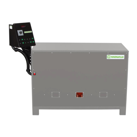
Magnaflux CSV Series User manual

Revised January 2020
www.magnaflux.com
Page | 1-0
CSV SERIES

Revised January 2020
www.magnaflux.com
Page | 1-1
TABLE OF CONTENTS
GENERAL SAFETY INSTRUCTIONS
SECTION 1 - EQUIPMENT SPECIFICATIONS..............................................................................1-3
Scope of this Manual...........................................................................................................1-3
Purpose of the Equipment...................................................................................................1-3
Equipment Characteristics ..................................................................................................1-3
Equipment Specifications....................................................................................................1-4
Equipment Warranty……………………………………………………………………………..... 1-6
SECTION 2 - INSTALLATION and STORAGE..............................................................................2-1
General...............................................................................................................................2-1
Installation...........................................................................................................................2-1
Preparation for Storage or Shipment.................................................................................2-19
SECTION 3 - OPERATING INSTRUCTIONS.................................................................................3-1
Operating Controls and Indicators.......................................................................................3-1
Daily Start Up and Operation Check List.............................................................................3-2
Normal Set-up...................................................................................................................3-25
Magnetizing Procedures ...................................................................................................3-25
Shutdown..........................................................................................................................3-26
Emergency Shutdown.......................................................................................................3-26
SECTION 4 - MAINTENANCE .......................................................................................................4-1
General...............................................................................................................................4-1
Daily Operator Maintenance................................................................................................4-1
Weekly Operator Maintenance............................................................................................4-1
Monthly Operator Maintenance...........................................................................................4-2
Periodic Internal Maintenance.............................................................................................4-2
SECTION 5 –TROUBLESHOOTING.............................................................................................5-1
Troubleshooting Guide........................................................................................................5-2
SECTION 6 –DRAWINGS & SPARE PARTS LIST.......................................................................6-1
SECTION 7 –HOOD INSTALLATION...........................................................................................7-1

Revised January 2020
www.magnaflux.com
Page | 1-2
GENERAL SAFETY INSTRUCTIONS
This manual provides information on how to install, operate, and maintain your Magnaflux magnetic
particle inspection machine.
Read these instructions carefully before operating or servicing your machine.
•Only trained personnel should operate or service this machine. Be familiar with your facility and local
procedures as well as Lock Out/Tag Out requirements before working with this machine.
•Read this entire manual before operating this machine.
•Wear safety glasses that conform to ANSI Standard Z87.1 while operating this machine.
•Do not wear loose clothing or jewelry while operating or servicing this machine.
•Inspect the machine daily for unsafe conditions; replace any worn or broken parts (see Section 4).
•Keep all unauthorized personnel away from the machine operating area.
•According to the American Conference of Governmental Industrial Hygienists (ACGIH) recommendations,
inspectors with pacemakers should avoid exposure to D.C. fields over 10 gauss; or 60 cycle A.C. field over
1.0 gauss. There are a variety of pacemakers with different susceptibilities to magnetic fields. Wearers
should discuss pacemaker limitations with their physicians and learn more exactly what they should avoid,
and whether they should be exposed to magnetic fields before operating this equipment.
•When you are finished operating the machine, turn off all power.
•This machine was designed to help the end user comply with ASTM E-1444. Calibration frequency is
dictated by this standard

Revised January 2020
www.magnaflux.com
Page | 1-3
SECTION 1: EQUIPMENT SPECIFICATIONS
SCOPE OF THIS MANUAL
This manual provides essential information required for installation, operation, and maintenance of standard
Magnaflux CSV Series Stationary Power Pack Magnetic Particle Inspection Machines.
PURPOSE OF THE EQUIPMENT
The equipment is used to inspect ferromagnetic parts by means of the magnetic particle inspection method.
Magnetic particle inspection (MPI) is a non-destructive method for revealing surface, and, under certain
conditions, sub-surface discontinuities. It consists of three basic operations:
1. Application of magnetic particles.
2. Establishment of a suitable magnetic field.
3. Inspection and evaluation of particle accumulations.
Discontinuities may exist in raw material from which parts are made, or, they may occur during processing or
fabrication of the parts, or, they may exist as cracks due to excessive service stresses. Discontinuities are
considered defects if their existence is detrimental to the usefulness of the part. Magnetic particle inspection
can readily and reliably locate discontinuities revealing manufacturing and/or service-induced defects.
EQUIPMENT CHARACTERISTICS
Stationary power pack magnetic particle inspection units consist of a power pack that provides low-voltage,
high-amperage 3-phase full wave direct current for magnetization, and reversing 3-phase full wave direct
current for demagnetization on output 1. Demagnetization on outputs 2 and 3 is an Optional Feature.
The output current levels are governed by 3 separate current controls. Selection of outputs 1, 2, and 3 is done
through a color touch screen operator interface. A push button next to the operator interface initiates the timed
magnetizing current “shot.”
A digital ammeter provides a reading of the magnetizing current. The reading is held until the next current
“shot” is initiated.
Pertinent data (e.g., the unit’s serial number, electrical specifications, and duty cycle rating) may be found on
the Magnaflux Data Plate, located on the front side of the unit.

Revised January 2020
www.magnaflux.com
Page | 1-4
EQUIPMENT SPECIFICATIONS
CONVENIENCE OUTLETS 2 each 115 volts AC, 5 ampere (for Black Light)
Input Specifications
The equipment can be fused based on less than the maximum amperage draw due to the duty cycle. Refer to
NEC Code Section 630.31 Ampacity of Supply Conductors and Table 630.31(A) (2) Duty Cycle Multiplication
Factors for Resistance Welders (NPFA National Electric Code 2011).
Table 1-1 Electrical Input
Model
Series
Input
Volts AC
Phase
Load
(Amperes)
Recommended
Line Fuse (Amp-
eres)
CSV-10
380
415
460
575
3
3
3
3
245
220
200
160
200
175
150
125
Model
Series
Input
Volts AC
Phase
Load
(Amperes)
Recommended
Line Fuse (Amp-
eres)
CSV-15
380
415
460
575
3
3
3
3
360
340
300
240
300
260
230
190
Model
Series
Input
Volts AC
Phase
Load
(Amperes)
Recommended
Line Fuse (Amp-
eres)
CSV-20
380
415
460
575
3
3
3
3
500
450
400
325
400
350
300
250

Revised January 2020
www.magnaflux.com
Page | 1-5
Output Specifications
*All contacts current ratings are based on the maximum current through a 2000 amp/100 mv shunt.
NOTE: Testing is done using 30’ of 1000 MCM for CSV-10, 30’ of 1000MCM in parallel with double 30’ 4/0 for
CSV-15 and double 30’ 1000 MCM for the CSV-20.
Table 1-2. Magnetization and Demagnetization Output
Model
Series
Maximum
Current
(Amperes)
Current
Control
Demag
CSV-10
10,000
Continuously
Variable
In all cases
Reversing
Decaying DC
on Output 1
CSV-15
15,000
Continuously
Variable
In all cases
Reversing
Decaying DC
on Output 1
CSV-20
20,000
Continuously
Variable
In all cases
Reversing
Decaying DC
on Output 1
Seconds “On”
Seconds “Off”
CSV Series
At Maximum Output
0.5
20
Capacities
Table 1-7. Machine Weight
Model No.
Approximate Weight (Dry)
Approximate Weight (Crated)
Pounds
Kilograms
Pounds
Kilograms
CSV-10
3500
1588
4200
1906
CSV-15
4900
2223
5500
2495
CSV-20
5500
2495
7000
3176

Revised January 2020
www.magnaflux.com
Page | 1-7
PAGE LEFT BLANK
INTENTIONALLY

Revised January 2020
www.magnaflux.com
Page | 2-1
SECTION 2: INSTALLATION AND STORAGE
GENERAL
This section contains information required for unpacking, inspecting, and setting up the magnetic particle
inspection unit. Information for preparing the inspection unit for shipment and storage is also included.
INSTALLATION
Location of Unit
Consider the following requirements before selecting a permanent location for the inspection unit:
1. A power source of the proper voltage, frequency and phase (as designated on the Magnaflux Data
Plate located on the front side of the inspection unit) capable of providing current per the nameplate.
2. A minimum of four feet is required at both ends and the rear of the inspection unit to ensure adequate
space for servicing and ventilation.
3. A firm, reasonably level floor capable of supporting the inspection unit and the materials awaiting
inspection.
4. Adequate space to accommodate material storage, material movement, and access to the materials.
Unpacking
No special unpacking process is necessary. Observe normal precautions to prevent damage to inspection
unit, and adhere to standard practices for the removal of crating material, protective barrier materials and
preservatives.
Visually inspect the machine and Optional accessories for any apparent shipping damage, and to ascertain
that all accessories ordered have been received. If shipping damage is found, please contact the freight
company to report the damage before contacting Magnaflux Customer Service via phone at 847-657-5300, or
via e-mail at CS@magnaflux.com.
Leveling
Check the inspection unit to ensure it being level, shimming the legs as required. When the inspection unit is
level, secure it to the floor with a bolt through each leg.
Electrical Connections

Revised January 2020
www.magnaflux.com
Page | 2-2
The inspection unit as supplied is internally wired for operation from a power source as designated on the
Magnaflux Data Plate (located on the front of the inspection unit). When connecting the unit all local codes
should be followed. External wiring directions for operation on the designated voltage are as follows:
1. Open right side panel where the white disconnect switch is located, as shown in Figure 2-1 below, or
Optional disconnect, to gain access to input power terminal block. A punch out is required through the
roof of the unit to feed the customer’s power line. The punch out would be located on the back right
corner of the unit.
WARNING: Turn off and lock-out the external disconnect switch (not normally supplied)
before opening the right side panel. Failure to disconnect incoming power could result in
severe electrical shock or death.
Figure 2-1
2. Connect external power source to the terminal block on the rear right side of the inspection unit, or the
top connectors in the Optional disconnect.
WARNING: Magnetic particle baths can carry electrical current. Since operators will come in
contact with the bath during operation, proper grounding of the inspection unit is
essential. Failure to ground the inspection unit properly may result in an electrical shock
hazard. Check the ground connection with an ohmmeter. A reading of 0 ohms denotes
an acceptable ground connection.
Black Light Installation
(Optional Accessory)

Revised January 2020
www.magnaflux.com
Page | 2-3
1. Plug black light cord into the BLACK LIGHT outlet on either end of the inspection unit. Test ground fault
interrupt for proper operation. Figure 2-2 below shows the outlets.
2. If using the optional 600086 BLACK LIGHT with the integral mag shot button, plug the mag shot cable into
the REMOTE MAG socket conveniently located on either end next to the BLACK LIGHT outlets.
Figure 2-2
Verification of Functions

Revised January 2020
www.magnaflux.com
Page | 2-4
After the customer’s power has been connected to the unit, and the right side panel put back on, the unit can
be powered up. The external white disconnect switch, as shown below in Figure 2-3, located on the right side
of the unit, should be flipped up to turn on.
Figure 2-3
To power up the unit, press the middle red button called MASTER ON, as shown in Figure 2-4 below. This is
located on the front side of the unit. When the unit is powered on, the POWER ON light, which is the far left
button; lights up. If for any reason the unit needs to be shut down immediately, the far right button can be
pushed, and it will shut down the unit. This is called the E-STOP button and shown below as well.
Figure 2-4
The standalone pedestal connects to the front panel as shown by the cord in Figure 2-4 on the previous page.
Figure 2-5 below shows the standalone pedestal.

Revised January 2020
www.magnaflux.com
Page | 2-5
Figure 2-5
MANUAL MODE
After the unit is powered up, and the main screen appears, as shown in Figure 2-6 below, the unit is ready to
operate. The unit can be operated in Manual or Recipe mode. When the main screen appears, the MANUAL
ON green colored button should appear in the bottom center of the screen.
Figure 2-6
If it shows RECIPE ON instead, as shown in Figure 2-7, the operator would push the RECIPE ON button, and
the button would change back to MANUAL ON as shown in Figure 2-6.

Revised January 2020
www.magnaflux.com
Page | 2-6
Figure 2-7
With the MANUAL ON button lit, the operator would then push the Cycle 1 ON button located on the bottom
right section of the main screen. This is shown in Figure 2-8 below. This sets the unit so that only one cycle
will be performed after the Mag button is pushed. The cycle is dependent on which outputs are turned on and
off, which will be detailed next in the manual.
Figure 2-8
Next, the operator will connect a minimum of 30’ of 1000 MCM for CSV-10 or 30’ of 1000 MCM in parallel with
double 30’ 4/0 for CSV-15 to the bus bars on output 1 shown in Figure 2-9.

Revised January 2020
www.magnaflux.com
Page | 2-7
Figure 2-9
From the main screen, the operator would push the Current Type button located in the bottom left corner of the
screen, in the Setup Screens section. This is shown in Figure 2-10 below.
Figure 2-10
The screen below shown in Figure 2-11 will appear, and the parameters for Outputs 1, 2, and 3 are shown.
The operator would push the FULL WAVE button located below Output 1 to turn on Output 1. Outputs 2 and 3
Output 1

Revised January 2020
www.magnaflux.com
Page | 2-8
will be turned off by pushing the OUTPUT OFF button. Output 1 should show “Output On,” and be the only
one in the lighter shade of green.
Figure 2-11
With only Output 1 activated, the Mag Power needs to be set. The operator would push the box located next
to Mag Power on the screen, and a keypad will appear, as shown below in Figure 2-12. The operator would
enter a value of 20, and then push the blue ENT button. The keypad will disappear, and the screen will go
back to showing all the outputs.
Figure 2-12
The Demag Power needs to be set next, and is done the same way as the Mag Power was set up. The
operator would push the box next to Demag Power, and enter a value of 25, and then press the blue ENT

Revised January 2020
www.magnaflux.com
Page | 2-9
button. The Mag Shot time then will be set, and is done by pressing the box next to Mag Shot Time. The
operator would enter a value of 0.5 seconds, and then press the blue ENT button.
After these parameters are set for Output 1 only, as this is the only activated output, and the cables are
connected to the bus bars of output 1, the operator would push the Mag button located next to the color touch
screen interface. This button is shown in Figure 2-13 below.
Figure 2-13
On the main screen, as shown in Figure 2-14 below, it will show the amperage output for Output 1, and hold
that value.
Figure 2-14
After initiating a magnetizing shot, the operator would then push green DEMAG button located on the main
screen, which is located in the bottom center of the screen, and shown below in Figure 2-15. During

Revised January 2020
www.magnaflux.com
Page | 2-10
demagnetization, a message will appear as shown in Figure 2-16 below. Once the demagnetization cycle is
complete, the message will disappear, and the main screen will appear again.
The operator will now connect a minimum of 30’ of 1000 MCM for CSV-10 or 30’ of 1000 MCM in parallel with
double 30’ 4/0 for CSV-15 to the bus bars on output 2 as shown in Figure 2-17, and remove the cables from
output 1. All three outputs and bus bars are shown below in Figure 2-17. Output 1 is the far left one in the
picture, output 2 in the middle, and output 3 to the far right.
Figure 2-17
From the main screen, the operator would push the Current Type button located in the bottom left corner of the
screen, in the Setup Screens section. This is shown in Figure 2-18 below.
Figure 2-15
Figure 2-16
Output 2

Revised January 2020
www.magnaflux.com
Page | 2-11
Figure 2-18
The screen shown in Figure 2-19 on the next page will appear, and the parameters for Outputs 1, 2, and 3 are
shown. The operator would push the FULL WAVE button located below Output 2 to turn on Output 2. Outputs
1 and 3 will be turned off by pushing the OUTPUT OFF button. Output 2 should show “Output On,” and be the
only one in the lighter shade of green.
Figure 2-19
With only Output 2 activated, the Mag Power needs to be set. The operator would push the box located next
to Mag Power on the screen, and a keypad will appear, as shown below in Figure 2-20. The operator would
enter a value of 20, and then push the blue ENT button. The keypad will disappear, and the screen will go
back to showing all the outputs.

Revised January 2020
www.magnaflux.com
Page | 2-12
Figure 2-20
The Demag Power needs to be set next (Optional Feature for Output 2), and is done the same way as the Mag
Power was set up. The operator would push the box next to Demag Power, and enter a value of 25, and then
press the blue ENT button. The Mag Shot time then will be set, and is done by pressing the box next to Mag
Shot Time. The operator would enter a value of 0.5 seconds, and then press the blue ENT button.
After these parameters are set for Output 2 only, as this is the only activated output, and the cables are
connected to the bus bars of output 2, the operator would push the Mag button located next to the color touch
screen interface. This button is shown in Figure 2-21 below.
Figure 2-21
On the main screen, as shown in Figure 2-22 below, it will show the amperage output for Output 2, and hold
that value.
This manual suits for next models
3
Table of contents
Other Magnaflux Laboratory Equipment manuals