Magnaflux ETT User manual

Operating Manual
ETT Demagnetising Tunnel
ETT 150/250/350/450/550

1. IMPORTANT SAFETY INFORMATION
1.1 INSTRUCTIONS FOR SAFE USE
The operational safety of the ETT demagnetising tunnel is only guaranteed when
it is used as intended. The ETT is exclusively designed for demagnetising compo-
nents made of ferromagnetic material with a magnetic eect >100 µ.
Improper use may lead to damage or injury. The ETT must NOT be used
• in explosive environments
• for mechanical or thermal processing of workpieces.
Responsibilities of the operator
The operator is solely responsible for the consequences of improper use and
actions not described in this manual. The manufacturer - Magnaflux GmbH - assumes
no liability for any resulting damage. In the case of improper use, all warranty
claims are void.
The operator is obligated to ensure that the device is operated only by persons
who:
• are familiar with the basic regulations concerning industrial safety and
prevention of accidents.
• have been fully trained in the operation of the device. Personnel undergoing
training must be supervised while using the ETT.
• have read and understood this manual.
Responsibilities of other personnel
Only authorised personnel may carry out:
• transportation of the unit
• installation and commissioning
• connection of the power supply
• maintenance and repair work
All persons who are commissioned to work on the device are obligated to:
• observe the basic regulations regarding industrial safety and prevention of
accidents;
• read and strictly follow this operation manual before starting work.
Please contact Magnaflux GmbH with any questions regarding the use of this machine.
CONTENTS
1 Important safety information 1
1.1 Instructions for safe use 1
1.2 Applicable warning signs 2
1.3 Exposure to magnetic fields 2
2 Technical data 3
2.1 Dimensions 3
2.2 Electrical 3
2.3 Field strength 3
2.4 Environmental conditions 3
2.5 Size of workpieces 3
3 Operation 4
3.1 Operating elements 4
3.2 Function 4
3.3 Installation 5
3.4 Operating the ETT 5
3.5 Measuring field strength 6
3.6 Maintenance 6
4 Transportation 7
4.1 Preparing for transport 7
4.2 Transportation in original packaging 7
4.3 Transportation by crane 7
5 Decommissioning and disposal 8
5.1 Decommissioning 8
5.2 Disposal 8
- EC/EU Declaration of Conformity 8
This operation manual provides important advice for the safe and eective
handling of the device. The manual must be kept at the place of work and be
accessible to operators and maintenance personnel at all times.
1

1.2 APPLICABLE WARNING SIGNS
MAGNETIC FIELD STRENGTH
High magnetic field strengths during magnetising can lead to
health problems and negative eects on implants.
• Follow all general and specific regulations for the prevention
of accidents.
• Observe safety distances during magnetising.
RISK OF INJURY FROM HEAVY OBJECTS
Heavy objects may injure hands:
• Do not grip between objects and magnetising coil when
loading and unloading.
• Wear protective gloves.
SKIN IRRITATION THROUGH MATERIALS
Components in the chemical materials may lead to skin irrita-
tion or other health risks.
Always follow the safety instructions in the manufacturer’s
Safety Data Sheet when handling chemical materials.
HIGH ELECTRIC VOLTAGES CAN CAUSE LETHAL ELECTRIC
SHOCK AND BURNS
Work on the electrics of this unit must only be carried out:
• in compliance with applicable standards at the installation site;
• only by a qualified electrician.
IN AN EMERGENCY:
Immediately disconnect the ETT from the power supply.
The mains switch serves as a mains isolation.
• OFF position is marked ‘0’.
• ON position is marked ‘1’.
With the switch in the OFF position, the machine is isolated from the power supply
and the switch can be secured with a padlock.
1.3 EXPOSURE TO MAGNETIC FIELDS
DANGER TO LIFE FOR PERSONS WITH CARDIAC PACEMAKERS
Magnetic fields can interfere with cardiac pacemakers, insulin
pumps and other implanted devices.
DO NOT USE THIS EQUIPMENT:
• if you have a pacemaker, insulin pump or other implanted device.
• if you are pregnant.
• if you are under 16 years of age.
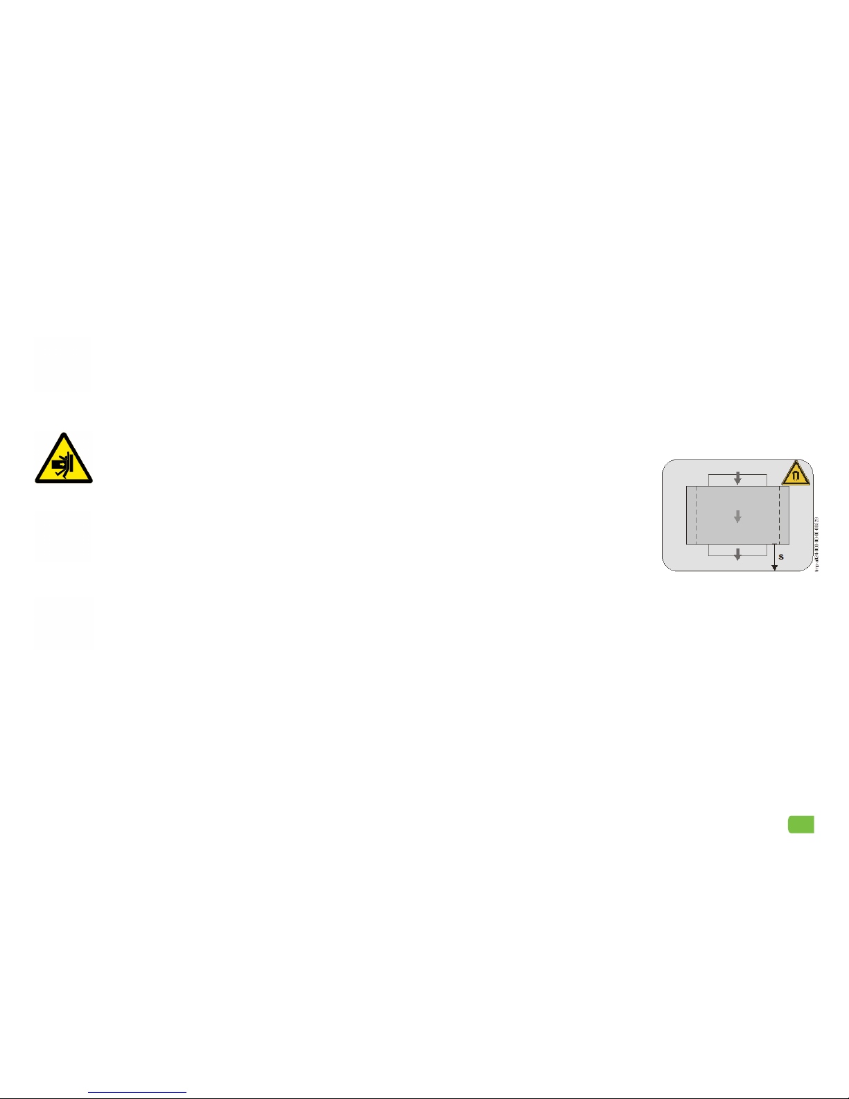
The grey shaded zone in this diagram
(right) shows the area of increased expo-
sure to magnetic fields. The operator must
measure and mark out the safety distance
in their own workplace, and maintain that
distance from the magnetising device
during operation:
• peoplewithoutbody-implanteddevices:
0.5 m / 20”
• people with body-implanted devices
(e.g. pacemakers): 5 m / 16’ 5”
In addition, the operator must ensure that
• only authorised and trained personnel are working in these areas
• the permissible values for short-term and partial body exposure are not
exceeded
• personal protective equipment (PPE) is used to prevent over-exposure.
Important: magnetic fields can penetrate through walls!
The specified safety distance results from the limits set out in the accident
prevention regulations BGV B11 as of June 2001 of the International Directive
for the Limitation of Exposure by Temporary Change in Electrical, Magnetic and
Electromagnetic Fields (ICNIRP), 1998.
According to Accident Prevention Regulation BGV B11, the ETT machine is assigned
the magnetic exposure group 1. The exposure group 1 covers areas with controlled
access, like work places.
S = area of increased exposure
2

2. TECHNICAL DATA
2.1 DIMENSIONS
Model Length (mm) Width (mm) Height (mm) Weight (kg)
ETT 150 325 260 260 24
ETT 250 325 390 390 46
ETT 350 325 480 475 75
ETT 450 325 580 577 90
ETT 550 325 680 695 100
All measurements and weights are approximate.
2.2 ELECTRICAL
IEC Protection Class II (double insulated)
2.4 ENVIRONMENTAL CONDITIONS
Temperature range during use 5oC to 45oC
Temperature range for storage 5oC to 55oC
Humidity during use and storage max. 90% relative humidity without dew
2.5 SIZE OF WORKPIECES
The ETT is exclusively designed for demagnetising workpieces made of ferro-
magnetic material with a magnetic eect >100 µ and maximum sizes as below
Model Maximum width (mm) Maximum height (mm)
ETT 150 145 145
ETT 250 245 245
ETT 350 345 345
ETT 450 445 445
ETT 550 545 545
Operation voltage:
AC 230 V, 50 Hz
Model Power consumption
ETT 150 0.5 kVA
ETT 250 1.2 kVA
ETT 350 2.2 kVA
ETT 450 3.1 kVA
ETT 550 3.6 kVA
Operation voltage:
AC 400 V, 50 Hz, N, PE
Model Power consumption
ETT 150 0.7 kVA
ETT 250 1.8 kVA
ETT 350 3.4 kVA
ETT 450 4.5 kVA
ETT 550 4.7 kVA
3
Standard 230 V, 50 HZ
Model Coil magnetising*
ETT 150 11 kA/m
ETT 250 9 kA/m
ETT 350 8 kA/m
ETT 450 6.5 kA/m
ETT 550 5.4 kA/m
Reinforced 400 V, 50 Hz
Model Coil magnetising*
ETT 150 13.5 kA/m
ETT 250 10 kA/m
ETT 350 10 kA/m
ETT 450 8 kA/m
ETT 550 6.2 kA/m
2.3 FIELD STRENGTH
* Tolerance within ±10%

3. OPERATION
3.1 OPERATING ELEMENTS
3.2 FUNCTION
If your workpiece has been magnetised with an AC current, it must be demagne-
tised using an AC current. For eective demagnetisation:
• there must be a field of alternating polarity and
• the field strength must continuously fall to zero.
The reduction of the field strength in the workpiece can happen:
• electrically, by reducing of magnetising current
• mechanically, through the continuous movement of the magnetic field.
Within the ETT demagnetisation tunnel, move the workpiece (either manually or via
a conveyor system) in the direction of the coil axis, into the magnetic field and then
out of the magnetic field of the coil.
The depth of the 50 Hz alternating field is approx. 2 mm. For a greater depth, we
can supply low-frequency generators with 16 2/3 Hz for all our ETT demagnetisa-
tion tunnels.
Main components:
1. Magnetising coil
2. Main switch
3. Connection cable and plug
There is an identification plate located near the main switch, where you will find im-
portant information regarding the device, the power supply and the manufacturer.
Your ETT device also displays the following symbols:
CE marking - indicates conformity with EU guidelines applicable
to the product.
Danger from magnetic fields; observe safety distances.
Use of this device by people with pacemakers and other body
implants is prohibited!
All direction and location
details in this manual refer to
the main working area of the
machine:
Behind
RightFront
Left
Field strength during demagnetisation
4

3.3 INSTALLATION
The demagnetising tunnels of the ETT series are designed for installation on a
work bench or integration with other machinery.
There are four tapped holes (M8) on the bottom of the unit for secure mounting of
the device. The coil housing is made of robust moulded plastic and is impervious
to dirt, humidity and temperature fluctuations.
Power is supplied by a power cable with plug. A mains switch is installed on the
side of the unit as a mains isolation device. When connecting the power supply:
• only use inert fuses.
• use suitable cables with regard to cable length and power supply conditions.
An low-frequency (LF) generator with a frequency of 16 2/3 Hz is available as an
accessory for the ETT. Workpieces which have been magnetised using DC can be
demagnetised by the LF operation. Contact Magnaflux GmbH for more information.
3.4 OPERATING THE ETT
Initial commissioning and subsequent use of the ETT demagnetising tunnel must
only be carried out by trained personnel. Observe the operating instructions and
the safety instructions for the device.
Following the procedure below for every use of the ETT:
1. Dismiss unqualified persons from the area.
2. Perform a visual inspection of the area and the ETT.
3. Check the power supply.
4. Turn on main switch.
5. Insert the workpiece into the ETT tunnel.*
6. Demagnetise the workpiece.
7. Measure residual field strength in the workpiece.
8. Remove workpiece from tunnel.
9. Turn o main switch.
* Ensure that the workpiece is placed centrally the tunnel for optimal demagne-
tising performance. If the workpiece is a complex shape, you may need to place
it in dierent locations and positions within the tunnel and measure the residual
magnetism each time, to find the best position for full demagnetisation.
1 = CORRECT installation position: ETT device standing on horizontal support
surface. Tightening torque of screws: 12 Nm
2 = INCORRECT installation. If you require a vertical mounting position, you MUST
contact Magnaflux GmbH before attempting to install the ETT.
High electric voltages can cause lethal electric shock and burns.
Electrical connections MUST be made:
• in accordance with the wiring diagram and the information
provided on the type plate;
• in compliance with applicable standards at the installation site;
• only by a qualified electrician.
5

3.6 MAINTENANCE
High electric voltages can cause lethal electric shock and burns.
Faulty, damaged or disassembled units can be dangerous
Work on the electrics of this unit must only be carried out:
• in compliance with applicable standards at the installation site;
• only by a qualified electrician.
The demagnetising devices of the ETT series are designed to be maintenance-free.
That said, we recommend you regularly check the cover of the unit and the power
supply cable for cracks, wear-and-tear, and other damage. If in doubt:
1. Switch o the device immediately
2. Secure it against being switched on again.
3. Isolate it from the power supply (pull out the mains plug).
Replacement parts and consumables
Use only original parts or parts approved by Magnaflux GmbH. The use of spare
parts from third party manufacturers may damage the device and make it hazard-
ous to use. Magnaflux GmbH accepts no liability for damage resulting from the use
of unapproved parts.
Any other additions or changes to the device are not permitted without the written
consent of the manufacturer. If you are planning conversions, please contact the
manufacturer beforehand.
6
3.5 MEASURING FIELD STRENGTH
The intensity and range of the magnetic field are important parameters in magnet
particle testing. Always check the magnetisation when setting up the ETT for a new
workpiece.
The FSM-2 is a field strength meter designed for tangential measuring of magnetic
field strength. The display of the FSM-2 shows the field strength in A/cm both as
eective value and peak value.
How to use the FSM-2:
1. Magnetize the workpiece.
2. Place the FSM-2’s probe on the workpiece.
3. Read the magnetic field strength in A/cm on the display.
For more information on the FSM-2, contact Magnaflux GmbH.

7
4.2 TRANSPORTATION IN ORIGINAL PACKAGING
The ETT is delivered in its original packaging on a pallet and should be transported
in the same condition as close as possible to the installation location.
The ETT, in its original packaging, is bolted to the pallet and secured with straps.
DO NOT tip or tilt the unit more than 10° from the horizontal. Relevant warnings are
placed to be clearly visible on the packaging.
The gross weight of the machine, including packaging, is stated in the shipping
documents.
Procedure:
1. Insert the forks of a suitable forklift into the transport pallet at the marked positions.
2. Lift the machine slightly and carefully.
3. Transport the machine, keeping it close to the ground, to the unpacking location.
4. Lower the machine into place slowly and carefully. Do not reach under the machine.
Unpacking the ETT:
1. Cut and remove any protective shrink wrap.
2. Open the crate.
3. Unscrew the fastening bolts and carefully loosen the straps.
4. Lift small parts and accessories o the pallet by hand.
4.3 TRANSPORTATION BY CRANE
Procedure:
1. Turn o main switch and disconnect all power
supplies.
2. Remove fastening bolts from floor.
3. Secure the cable harness to the unit.
4. Lift the machine slightly and carefully. Pay attention
to the balance; if necessary, adjust the cable
lengths so that the unit is hanging straight on the
crane.
5. Transport the unit, keeping it close to the ground,
to its new location.
6. Lower the unit into place carefully and slowly.
4. TRANSPORTATION
WARNING: Lifted loads can fall and cause severe injury and/or
damage to property.
Machines and machine components must only be lifted or
transported with appropriate lifting equipment suitable for the
weight and dimensions of the machine.
Transport, disassembly and assembly of the system must only be carried out by
specially trained personnel who must:
• Comply with relevant local regulations for work spaces.
• Refer to the specifications in section 2: TECHNICAL DATA of this manual.
4.1 PREPARING FOR TRANSPORT
You will need the following in order to transport the ETT demagnetisation tunnel:
• a crane with suitable rope harness.
• a forklift truck or pallet truck.
Only attach the forklift or pallet truck to the intended receptacles on the base. Any
other anchor points are not permitted.
Procedure:
1. Decommission the machine (take it out of operation).
2. Inspect the condition and load-bearing capacity of the floor at the intended
installation location, and along the entire transport route. Note: the ETT must
only be installed on a level and firm surface.
3. Specify and mark the exact installation location.
4. Determine the transport route and remove possible obstacles.
5. Keep unauthorised personnel away from the transport route and installation
location. Cordon o these areas, if necessary.

EC/EU DECLARATION OF CONFORMITY
FOR MAGNAFLUX STANDARD SMALL DEVICES
We hereby declare that this equipment complies with the follow-
ing EU Directives. The device has been tested and approved. Any
modification made to the device without our written consent will
invalidate this declaration.
Applicable EC/EU Directives:
Low Voltage Directive (LVD) 2014/35/EU
Electromagnetic Compatibility (EMC) Directive 2014/30/EU
Equipment model: Demagnetisation tunnel
Equipment type: ETT
Serial number: ................................................
Applied harmonised standards:
EN 60204-1:2014, DIN EN ISO 9934-3:2015
Other applicable standards and specifications:
DIN VDE 0100-410:2007, DIN VDE 0100-540:2012
Authorised person for documentation:
Mr. Georg Koch, Quality Management Ocer
Address:
Magnaflux GmbH, Bahnhofstr. 94-98, D-73457 Essingen, Germany
Person responsible: Signature:
Sales/Design Manager
Mr. Silvio Georgi
Date: 01/01/2017
8
5. DECOMMISSIONING AND DISPOSAL
High electric voltages can cause lethal electric shock and burns.
Work on the electrics of this unit must only be carried out:
• in compliance with applicable standards at the installation site;
• only by a qualified electrician.
5.1 DECOMMISSIONING
To decommission your ETT unit (i.e. to take it out of operation).
1. Switch o the device
2. Disconnect the power supply or unplug the plug.
3. Roll up the power cable and secure it to the unit.
5.2 DISPOSAL
Before disposal, check that all power supplies to the ETT have been disconnected.
Check your local regulations for disposal. Batteries, paint, varnish, chemicals
substances (e.g. solvents, cleaning agents, etc.), adhesives, fluorescent tubes,
energy-saving lamps, used oil and oil filters are harmful to health and the environ-
ment and need to be disposed of separately.
Procedure:
1. Decommission the unit.
2. Dismantle the unit.
3. Sort the parts by material, e.g. metals, plastics, composites, electronic components.
4. Dispose of all parts in accordance with local regulations.

Bahnhofstr 94-98, 73457 Essingen, Deutschland
Telephone: +49 (0) 7365 81-0 Fax: +49 (0) 7365 81-449
Email: sales.de@magnaflux.com Web: eu.magnaflux.com/de
Faraday Road, South Dorcan Industrial Estate, Swindon, SN3 5HE, UK
Telephone: + 44 (0)1793 524566 Fax: +44 (0)1793 490459
Email: sales.eu@magnaflux.com Web: eu.magnaflux.com
Table of contents
Other Magnaflux Laboratory Equipment manuals