Magnaflux Y6 Yoke User manual


HANDBOOK
Y6 ELECTROMAGNETIC YOKE
Part Numbers: 001Y022, 001Y020, 001Y004
HANDBOOK
Y6 ELECTROMAGNETIC YOKE

Certicate of Conformity
Y6 Yoke
Serial Number:
Date of Manufacture:
Certied that the above item conforms to and meets the requirements of
the following:
EC Directives
2006/95/EC
2014/30/EC
Specications
ASME V ART7
ASTM E709
ASTM E1444
EN-ISO 9934-3
MIL-STD-271
Certicate is issued under the auspices of the Equipment Product Manager:
Magnaux (A Division of ITW Ltd),
Faraday Road, South Dorcan Industrial Estate,
Swindon, Wiltshire, SN3 5HE, UK
Tel: +44 (0)1793 524566
Fax: +44 (0)1793 490459
Email: sales@magnaux.co.uk
www.eu.magnaux.com
4.2 EQUIPMENT AND ACCESSORIES
Y6 Yoke Kit
In kit form, the Y6 Yoke is supplied with black magnetic
ink, white contrast paint, a wire brush and a duster, all
housed in a strong, attractive carrying case.
A light source, attached to one leg of the Y6 Yoke, is
activated by the magnetic eld and switches on auto-
matically during testing. Ideal for darker corners.
Part number: 002L115
L-10 Magnetising Coil
Developed for testing shafts, spindles and similar parts.
• Ideal for inspecting for transverse cracks
• Components are magnetised and demagnetised with
the same coil
• 110V operation
• Suitable for wet and dry Magnetic Particle Inspection
(MPI) methods
• Footswitch provides continuous control
Part number: 008C020
Certied Test Weights
AC Test Weight (4.5Kg) Part Number: 026T018B
DC Test Weight (18Kg) Part Number: 026T018A
9

4. RECOMMENDED PRODUCTS
4.1 CHEMCIAL CONSUMABLES
Prepared Inks
Flash point
(PMCC)
Viscosity
(mm2/s)
Density
(g/cm3)
Particle
size (µm)
Settlement
volume
OIL-BASED (high-ash, low-odour kerosene base)
MAGNAGLO® 410HF 93 oC3.45 0.81 7 - 25 0.12% V/V
MAGNAGLO® 14HF 93 oC3.45 0.81 2 - 25 0.25% V/V
MAGNAGLO® 7HF 93 oC3.45 0.81 0.6 - 2.5 2.5% V/V
WATER-BASED
MAGNAGLO® WB-12 N/A N/A 1.2 7 - 9 0.1 - 0.4 ml
MAGNAGLO® WB-655 N/A N/A 1.1 3 - 5 0.13 - 0.21 ml
Dry Powders
Max. working
temperature Description
MAGNAVIS® 1 Grey 315 oCMAGNAVIS dry powders have closely-
controlled particle size and shape, and
come in a range of colours to give the best
possible contrast on a wide variety of n-
ishes. For best results, the powder should
be cloud-applied near the surface while the
current is owing.
MAGNAVIS® 3A Black 230 oC
MAGNAVIS® 8A Red 175 oC
Contrast Paint
Use MAGNAVIS® WCP-2 white contrast paint when the contrast between the test surface
and the ink/powder is not clear enough for inspection. Apply a thin coating for WCP-2 to
the surface prior to testing.
Specications
All the products above meet the requirements of ASTM E1444. Our oil-suspended inks
and concentrates meet AMS specications, plus appropriate industrial and Government
specications, Certications are available on request.
1. IMPORTANT SAFETY INFORMATION
DANGER TO PERSONS WITH CARDIAC PACEMAKERS
MAGNETIC FIELD RISK: persons susceptible to strong magnetic
elds, including those with pacemakers, are advised not to use
or approach this equipment without seeking professional advice.
Magnetic elds can, in some cases, interfere with cardiac pace-
makers so if you wear a pacemaker, you must get a clearance
certicate from your doctor before using this yoke.
DANGER OF ELECTROMAGNETIC FIELDS
Strong magnetic elds can have serious health effects.
DO NOT USE THIS YOKE:
• if you have a pacemaker, insulin pump or other implanted device.
• if you have any metallic implants.
• if you are pregnant.
• for more than 8 hours a day.
• DO NOT smoke while performing Non Destructive Testing (NDT).
• DO NOT operate the Y6 Yoke for longer than 3 seconds ON followed by 10 seconds
OFF (i.e. a 23% duty cycle).
• If the Yoke becomes too hot to hold in your bare hand, this is a sign that the duty cycle
has been exceeded. Stop inspecting and wait for the Yoke to cool before continuing.
• DO NOT use any means to permanently operate the Yoke switch.
• DO NOT use the supply cable to pull, lift or carry the equipment.
• When the Yoke is switched OFF, the magnetic attraction to the tested component will
be weakened and either the part or the Yoke could fall and cause injury.
18

72
Distance from hand
grip of yoke (mm)
Measured magnetic
ux density (mT)
70 2.00
200 0.32
400 0.045
5,000 0
Exposure to electromagnetic elds is highest
within a 0.5m radius of the yoke.
s
Area of increased exposure
1.1 SAFETY DISTANCES
The regulations below recommend that, while the yoke is in use, all personnel (other than
the operator) should maintain the following minimum safety distances from the yoke:
• people without body-implanted devices: 7cm / 3” (ref. A); 20cm / 8” (ref. B)
• people with body-implanted devices (e.g. pacemakers): at least 5m / 16ft.
(ref. A) BGV B11 Accident prevention regulation - Electromagnetic elds (June 2001).
(ref. B) International Commission on Non-Ionizing Radiation Protection (ICNIRP) (1998).
1.2 FLAMMABILITY
The Y6 Yoke is designed to be used in conjunction with appropriate chemicals as a means
of non-destructive testing (NDT) for defects, such as cracks, on a wide range of manufac-
tured components. Some chemicals may produce a ammable atmosphere at the point
of use so it is important that the testing is carried out in a well-ventilated place and that all
sources of ignition are excluded.
Good-quality NDT chemicals, such as Magnaux magnetic inks and powders, are formu-
lated to minimise the risk of a ammable atmosphere when correctly used.
3.1 COMPONENTS AND OPERATING ELEMENTS
Item Description Part number Quantity
1Cable, 3 core 001C063 3.75 m
2Bush 014B027 1
3Leg/foot assembly 075C004 2
4Switch kit: switch, rubber cover, insulated metal
cover, screws 005K026 1
5Cable cover 17771A3 1
WARNING: DO NOT REPLACE ANY PARTS WITH ANYTHING OTHER THAN THOSE
RECOMMENDED BY MAGNAFLUX.

3. TECHNICAL SPECIFICATION
Part number 001Y022 001Y004 001Y013 001Y020
AC voltage (V) 50 110 115 230
Frequency (Hz) 50 50 60 50
DC voltage (V) - 12 - 12
Supply current (A) in air
AC 15 3.5 3.5 2.3
DC -8.5 8.5 2.5
Weight (kg) lifted at 140
mm pole spacing
AC 10.5 10.5 10.5 10.5
DC -32.0 -32.0
AC tangential eld strength at the central point
between the poles on a 500 x 250 x 10 mm
steel plate.
Pole spacing Field strength
35 mm 12 kA/m
140 mm 2 kA/m
250 mm 1.4 kA/m
The light source and leg assembly, which are activated by the magnetic eld, are switched
on automatically during testing - ideal for dark corners.
36
1.3 ELECTRICAL
Ensure that the protective conductor (earth) is continuous from the Y6 laminations through
suitable connections to the electrical supply.
Recommendations:
• If the supply to the Yoke is greater than 50V, use a Residual Current Circuit Breaker
(RCCB) or Earth Leakage Circuit Breaker (ELCB).
• If the switch area of the Yoke becomes wet with kerosene or water, disconnect it from
its supply until the area has dried.
• In damp conditions, choose a 50V or 110V Yoke operated from a supply that is centre
tapped to earth (55V-0-55V)
• If the Y6 shows signs of malfunctioning, or if cracks appear in the casing, take the Yoke
out of service immediately and have it examined by a qualied electrician. Cracking is
usually caused by dropping the Yoke or by twisting the articulated legs.
In many countries, it is a legal requirement that the electrical safety of equipment is
checked periodically, commensurate with use, but at least once a year. The basic tests
required are to check the condition and effectiveness of the electrical insulation and the
continuity of the protective conductor (earth). These tests can be performed using a
Portable Appliance Tester (PAT) or Portable Appliance Checker (PAC).

54
2. OPERATING THE YOKE
2.1 PRINCIPLE OF OPERATION
When the Yoke is connected to a suitable power source, depressing the ‘Push to test’
switch creates an intense magnetic eld between the Yoke legs. As the Yoke is applied
to a steel plate, the magnetic circuit is closed, and the magnetic eld enters the plate
between the legs of the Yoke at and near the surface. A surface crack across this eld cuts
the magnetic circuit, the two sides of the crack become opposite poles of a magnet and
a leakage eld occurs in the air above the crack. Magnetic particles are attracted by this
leakage eld and mark its location.
2.2 SAFE USE OF THE YOKE
Our yokes manufactured to the highest technical standards. You can ensure safe
operation of your yoke by observing general safety and accident prevention regulations,
including the advice outlined below.
Before using the Yoke:
• Familiarise yourself with the yoke’s construction and method of operation. If necessary,
contact the manufacturer - Magnaux GmbH - for instruction/training.
• Ensure it is physically undamaged.
• Ensure the cable is free from cuts which expose the wiring.
• Tighten the articulated joints if they are excessively loose.
During use:
• Follow the operating instructions carefully.
• Observe the safety distances (see section 1.1) and time limit for usage.
• Wear appropriate personal protective equipment to protect yourself from over-
exposure to electromagnetic elds.
• Do not allow untrained personnel to operate the yoke; improper use of the yoke can
be hazardous to health.
• Only allow authorised personnel who are aware of the potential dangers of electro-
magnetic exposure into the areas where the yoke is being used.
• Do not attempt to repair or rebuild the yoke unit.
2.3 INSTRUCTIONS FOR USE
1. Place the Yoke on the workpiece perpendicular to the direction of the cracks. The
double-jointed articulated legs can be moved in two directions at each joint.
2. Adjust the spacing between the legs to between 25 and 250mm. If the part is an
irregular shape, contour the feet to ensure a good at contact point.
3. Trigger the switch and apply the inspection medium (wet or dry). Surface crack
indications will form immediately (for enhanced sensitivity, use a uorescent magnetic
ink with a high-intensity black light).
4. Repeat as required, moving the Yoke over the part. Each placement of the Yoke will
nd cracks in a 150 x 150mm area.
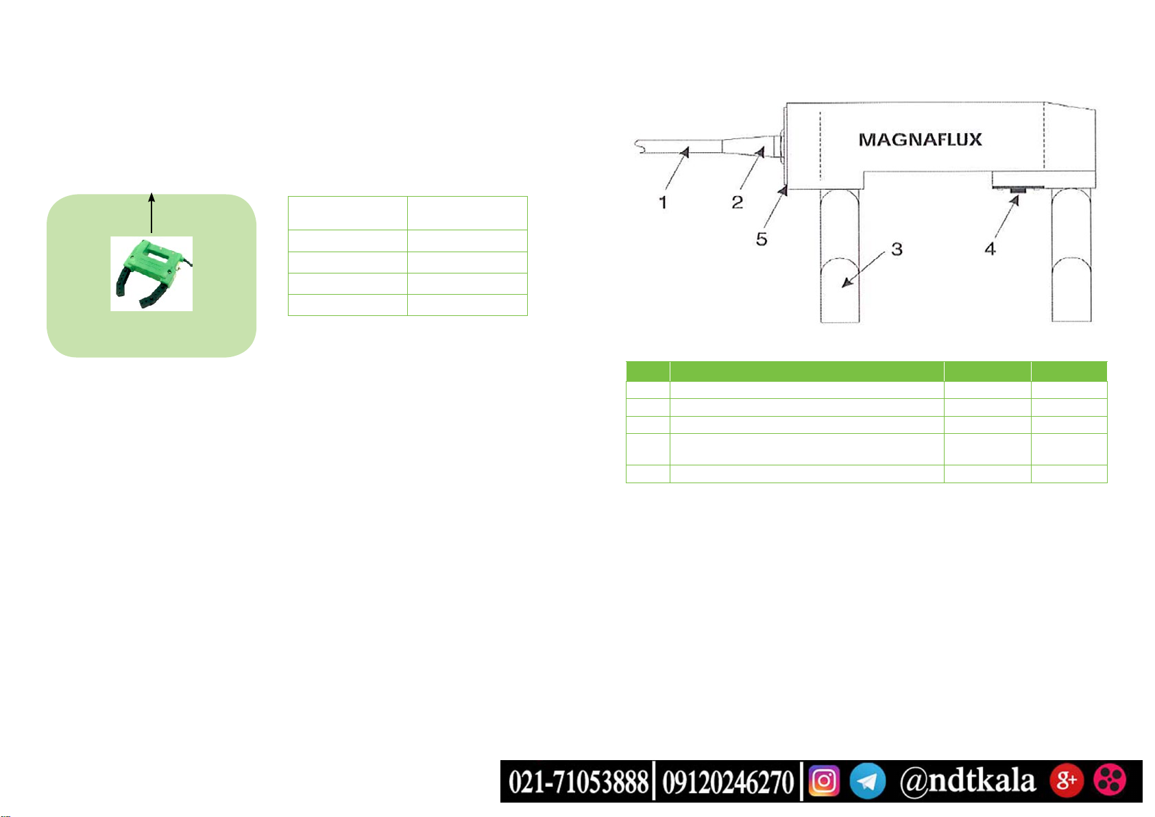
Laminar magnetic iron provides maximum efciency with light weight. The trigger switch
is easily operated without changing hand positions.
Magnetic contact exists only between the Yoke and the test piece, so the switch, which
is completely enclosed by a rubber gasket, is the only break in the electrical circuit. This
means that arcing on the part itself is impossible.
To detect transverse cracks in mounted spindles, rear axles and other light parts, the Y6
Yoke can be supplemented by a magnetising coil (e.g. Magnaux L-10 Magnetising Coil).
Other manuals for Y6 Yoke
1
This manual suits for next models
3
Table of contents
Other Magnaflux Tools manuals