MAGNATRAC RS1000 User manual

MMAAGGNNAATTRRAACC®
RS1000
Operator’s / Technical Manual
C. F STRUCK CORPORATION - CEDARBURG, WISCONSIN 53012

Very Important Facts
The following are random facts that will be ex-
panded on within this Manual. They are brought
to you “first” to impress upon you their primary im-
portance in preventing damage to your RS1000
and also to protect your safety and prevent costly
and unnecessary maintenance expenses.
SAFE B OCKING DIAGRAM
When “blocking” your Crawler off the ground for
service, be aware that you should not apply a
“pointed force”, like the end of a hydraulic jack, in
the area marked as “unsupported” (below)!
TRACKS
Avoid climbing a pile of loose material and
counter-rotating your Tracks (“cork-screwing”).
This action forces unnecessary amounts of mate-
rial into your Tracks and can cause derailing of
Tracks.
TRACK C UTCHES
Do not “jam-on” your clutch controls as this pre-
maturely wears them. Operate the clutches
smoothly and work into your load.
ENGINE TORQUE
The greatest amount of power (drawbar torque)
your Crawler can deliver is near the Engine’s mid-
speed range. To go faster, your Engine’s “drawbar
torque” will be diminished by having to go faster.
Doing all your heavy work at mid-speed does
three things: t keeps the Engine cooler working
at a slower speed, gives you maximum drawbar
torque, and at the same time does it at a speed
that provides time to make “attachment adjust-
ments” on the go!
You’re encouraged to completely read this Man-
ual to get a firm over-view of: how your Crawler
operates , significant safety points, and also main-
tenance tips on how to increase your Crawler’s
life.
PARKING BRAKE
Never forget to disengage your Parking Brake
...............BEFORE you drive away. f you fail to
disengage the Parking Brake, it will wear very rap-
idly and be of no value in an emergency!
UBRICATION OF
POWER SHAFT ENDS
Read and understand the “Special Note” in the
“Belt nstallation” section of this manual. By fol-
lowing it ‘s simple lubrication instructions your can
save yourself a lot of work, and potential expense
in the future and make Belt changing much easier.
Unsupported
Area!

Congratulations…
on your purchase of a quality-built, American
made compact Crawler. We are confident that the
dependability and economical performance of
your Struck Crawler will prove that you made a
wise choice.
The purpose of this Manual is to acquaint you with
the RS1000 Magnatrac Crawler. This Manual ex-
plains how to operate and service your Crawler,
and how to maintain its high operating efficiency.
nstructions are given clearly, with the intention of
making these operations as easy as possible.
Keep this Manual in a convenient place for quick
and easy reference. Use it as a guide whenever
questions arise. You have purchased a depend-
able, sturdy Crawler, but only by operating and
caring for it properly can you expect to receive the
service and long life for which it was designed.
f in the future you need new parts to replace
those that may be worn, insist on genuine Struck
parts. They are exact duplicates of the originals,
made from the same patterns and of the same
high-quality materials.
When ordering parts, always be sure to give the
following information for your Crawler:
Model Number:
Serial Number:
Engine Model Number:
Engine Serial Number:
C. F. STRUCK CORPORATION
W51-N545 STRUCK LANE
CEDARBURG, W SCONS N 53012
Phone: (262) 377-3300
Fax: (262) 377-9247
Copyright 2008 (Version 5.14.08)
TO THE OPERATOR
RECOGNIZE
SAFETY
INFORMATION
This is the safety-alert symbol. When
you see this symbol on your Crawler or
in this Manual, be alert to the potential
for personal injury.
UNDERSTAND SIGNA WORDS
A signal word — DANGER, WARN NG, or CAU-
T ON — is used with the safety-alert symbol.
DANGER identifies the most serious hazards.
Safety labels with the signal word DANGER or
WARN NG are typically near specific hazards.
General precautions are listed on CAUT ON
safety labels. CAUT ON also calls attention to
safety messages in this Manual.
FO OW SAFETY INSTRUCTIONS
Carefully read all safety messages in this Manual
and on your Crawler and Attachment safety labels.
Follow recommended precautions and safe oper-
ating practices.
Keep safety labels in good condition. Replace
missing or damaged safety labels.
To keep your Crawler running efficiently, read the
instructions in this Manual.
Left side, right side, front, and rear are viewed by
facing in the direction of the Crawler’s forward
travel.
Record your Crawler serial numbers in the space
provided. You need this information when you
order parts.
1

SAFETY RU ES
Reports on accidents show that care-
less use of machinery causes a high
percentage of accidents. You can avoid
many accidents by following the safety
rules on these pages. Study these rules carefully
and enforce them on the job
.
SAFETY BEFORE STARTING OR
OPERATION
The Crawler should be operated only by persons
approved to do so.
Clothing worn by the operator should be fairly tight
and belted.
Fasten a first aid kit to the Crawler.
Fasten a fire extinguisher to the Crawler. Keep
the extinguisher fully charged. Learn to use it cor-
rectly.
f the Crawler has an unsafe condition, do not op-
erate. Put a tag on the Track Drive Controls.
Do not start or operate the Crawler unless you are
in the operator’s seat.
Before you start the Engine, be sure there is
plenty of ventilation.
Keep hands, feet, and clothing away from power-
driven parts.
Fasten a slow-moving vehicle sign to the rear of
the Crawler.
Guards, shields, and other protective devices
must be in place and in good condition.
Before you start or operate the Crawler, clear the
area of all persons and obstacles.
OPERATION SAFETY
When you operate the Crawler, do not allow any-
one to ride on the Crawler or its equipment.
Drive at safe speeds at all times, especially on
rough ground and hillsides.
Carry the Bucket or Blade as low as possible at
all times, especially when you work on a hillside
or back up a steep hill.
Do not drive too close to the edge of a ditch or ex-
cavation.
Watch for overhead wires. Do not touch wires
with any part of the Crawler or its Attachments.
Do not leave your Crawler unattended with the En-
gine running.
Keep work areas as level as possible.
When loading logs with the Log Forks, make sure
the logs are balanced.
When you drive out of a ditch or excavation, or up
a steep hillside, or when Crawler is hitched to a
heavy load, engage Track Drive Controls slowly. f
the front of the Crawler comes off the ground, re-
lease Track Controls immediately.
Do not use the Crawler as a battering ram.
Do not guide cable onto Winch Drum with your
hands.
When you drive the Crawler on a road, use the
correct lights to warn operators of other vehicles.
Before you move any equipment, be sure all per-
sons are away from the Crawler.
When the Crawler is operating, only the operator
should be on it.
f it is necessary to make checks with the Engine
running, always use two people...the operator at
the controls should be able to see the person
doing the checking
KEEP HANDS AWAY FROM MOVING PARTS!
BEFORE YOU DISMOUNT:
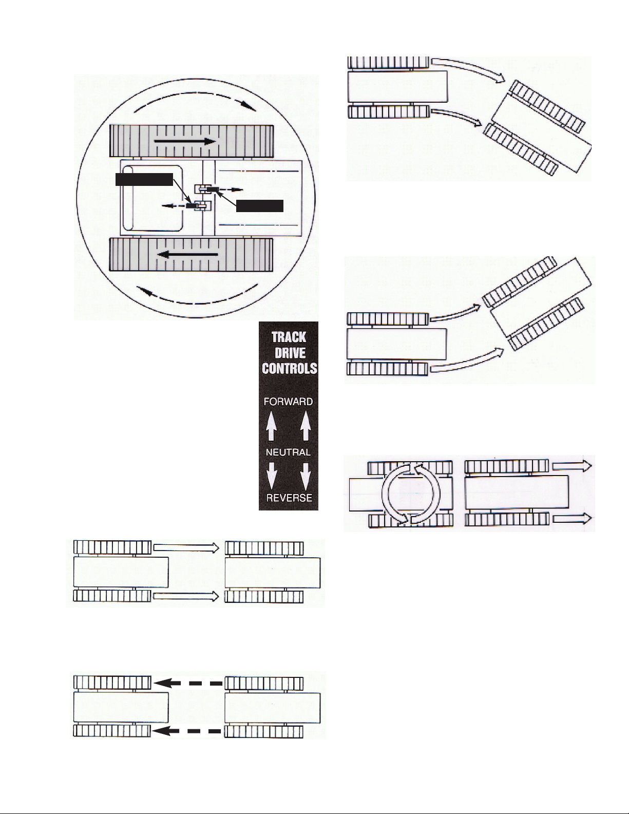
Move Track Drive Controls to neutral.
Engage Parking Brake ever
ower all equipment to the ground.
Stop Engine and remove the key.
2

SERVICE SAFETY
Be sure you understand a service procedure be-
fore you work on the Crawler.
Unauthorized modifications to the Crawler may
impair the function and/or safety and affect
Crawler life.
Do not work under Crawler or raised equipment
unless it is correctly supported...contact factory for
recommended procedures.
Before you work on the Engine or electrical sys-
tem, disconnect the battery’s “ground” ( - ) termi-
nal first! When work is finished, connect battery’s
“ground” terminal ( - ) last.
When driving connecting pins (Spring Pins), wear
goggles or safety glasses.
Do not run Engine while working on the Crawler.
Be careful when handling any type of fuel. Do not
smoke while filling the fuel tank or working on the
fuel system.
Check for faulty wiring or loose connections.
Do not lubricate or work on the Crawler while it is
moving.
When you work near the Track Springs, use ex-
treme care. Do not disassemble parts unless you
know the correct procedure and have correct
tools.
FIRE PREVENTION MAINTENANCE
Be prepared if an accident or fire should occur.
Know where the first aid kit and the fire extin-
guisher are located...know how to use them.
Check fire extinguisher for correct charge.
Do not smoke while refueling or handling highly
flammable material.
Shut off the Engine when refueling.
Use care in refueling if the Engine is hot.
Do not use open pans of gasoline or diesel fuel for
cleaning parts. Use good commercial, nonflam-
mable solvents.
Provide adequate ventilation when charging bat-
tery.
Do not check battery charge by placing metal ob-
jects across the posts.
Do not allow sparks or an open flame near battery.
Do not smoke near battery.
Never check fuel, battery electrolyte, or coolant
levels with an open flame.
Never use an open flame to look for leaks any-
where on the equipment.
Never use an open flame as light anywhere on or
around the equipment.
When preparing Engine for storage, remember
that inhibitor is volatile and therefore dangerous.
Seal and tape openings after adding the inhibitor.
Keep container tightly closed when not in use.
nspect electrical wiring for worn or frayed insula-
tion. nstall new wiring if wires are damaged.
Temperature in Engine compartment may go up
immediately after you stop the Engine. Be on
guard for fires.
Before you clean trash from the Engine compart-
ment, wait until the Engine has cooled. Open
Hood to cool the Engine faster. While the Engine
cools, clean trash from other areas.
Check for leaking fuel lines or fittings with a piece
of cardboard or wood. Do not use your hands.
Tighten loose fittings. f hoses are kinked, install
new parts.
3

NOISE PROTECTION
Prolonged exposure to loud noise can cause im-
pairment or loss of hearing. Wear a suitable hear-
ing protective device such as earmuffs or earplugs
to protect against objectionable or uncomfortably
loud noise.
START ENGINE ON Y FROM THE
OPERATOR’S SEAT!
Avoid possible injury or death from Crawler run-
away.
Do not start Engine by shorting across starter so-
lenoid terminals. Crawler may start and move if
normal circuitry is bypassed.
CAUTION: Never start Engine while
standing on ground. Start Engine only
from operator’s seat, with Brake en-
gaged.
nspect your Crawler carefully each day before
you start it. See “Pre-Start nspection”.
Clean your Crawler regularly.
4

CONTRO S
& INSTRUMENTS
Learn the location and purpose of all Controls,
nstruments and Warning labels. Thoroughly
study the Operator’s Manual furnished by the en-
gine manufacture and included with your Crawler
instructions.
A - EFT TRACK
C UTCH CONTRO
B - RIGHT TRACK
C UTCH CONTRO
C - THROTT E CONTRO
D - CHOKE CONTRO
E - HEAD IGHT SWITCH
F - KEY IGNITION SWITCH
G - CIRCUIT PROTECTOR
H - FUE VA VE
I - PARKING BRAKE
5
AB
C
D
E
F
G

A & B - EFT & RIGHT
TRACK C UTCH CONTRO S
INTRODUCTION: The turn
demonstrated (above) is the key to
your Crawler’s superior maneuver-
ability. t is accomplished with only
two controls, the A&BLeft & Right
Track Controls. The illustrations
(below) show how to maneuver
your crawler in other turns.
MOVING FORWARD:
To move straight ahead, simultaneously push
forward on both Left and Right Track Controls.
MOVING REARWARD:
To move straight rearward, simultaneously pull
rearward on both Left and Right Track Controls.
TURNING RIGHT:
To turn sharply right, push forward on Left Track
Control while holding Right Track Control in neu-
tral.
TURNING EFT:
To turn sharply left, push forward on Right Track
Control while holding Left Track Control in neutral.
COUNTER-ROTATING TRACKS
To counter-rotate Tracks (tightest turn possible),
push one Track Control forward while simultane-
ously pulling rearward on the other Track Control.
NOTE: When either Track Control is “slowly” re-
leased, it will automatically return to neutral.
NEVER allow Track Controls to “snap-back” to
neutral. See OPERAT ON section of this manual
for further instructions.
6
A - eft
B - Right

DASHBOARD CONTRO S
C - THROTT E CONTRO
The Throttle is lever operated, rotating in a wide
arc. This arc is divided into two speed ranges; the
slower Work Speeds and the faster Travel
Speeds. Your Crawler has maximum “pushing
force” (maximum torque) at the mid-range speed
but with a declining level of torque as you increase
your travel speed.
Though all crawlers by their design are somewhat
“rough riding”, you can minimize the “roughness”
by traveling at the lowest speeds when going over
hard surfaces.
D - CHOKE
The Choke Control is lever operated. Rotate the
lever counter-clockwise to increase engine chok-
ing; rotate clockwise to decrease engine choking.
(Consult engine manual for more information).
E - HEAD IGHT SWITCH
The Headlight Switch is a basic “Pull ON”, “Push
OFF” switch. Behind the Switch is a replaceable
Safety Fuse. When replacing, use a new fuse of
the same amps as the one being replaced.
F - KEY IGNITION SWITCH
Switch is activated by rotating key clockwise.
Turning it fully clockwise will engage engine starter
...release key and it will re-
turn automatically to the
RUN “ON” position. Turn
fully counter-clockwise to
OFF position to stop en-
gine. Remove key.
G - CIRCUIT
PROTECTOR
The Circuit Protector pro-
tects the battery charging
circuit. (Consult engine
manual for more informa-
tion).
H - FUE VA VE
The Fuel Valve
Lever controls the
fuel to the carbure-
tor. Turn it OFF
when cleaning sed-
iment bowl on car-
buretor. (Consult
Engine Manual for
more information).
7
Hard Surface Travel
Maximum Torque
D
C
E
H
F
G

I - PARKING BRAKE
The Parking Brake acts both as a parking brake
and as an emergency brake.
To “engage” Parking Brake, pull Brake Handle up
firmly and loop it “up and over
”
the Carriage Bolt
provided...make sure handle edge is on top of Bolt
and behind “inside face” of Carriage Bolt.
To “disengage” Parking Brake, reverse the above
procedure and allow Brake Handle to rest on
Fender.
As the Parking Brake is also your emergency
brake, it’s extremely important to maintain its per-
formance with daily inspection. See Service sec-
tion of this manual for proper procedures.
EXTREME Y IMPORTANT:
As it’s mandatory to engage the Parking Brake be-
fore starting your crawler, always remember to
disengage it before driving away.
If you fail to disengage the Parking
Brake it will wear very rapidly and be
of no value in an emergency!!
8
DISENGAGED
- Brake Handle
- Brake Handle
ENGAGED
Carriage Bolt

OPERATION
PRE-STARTING INSPECTION
Before you start your Crawler for the first time
each day, perform the following checks:
ENGINE COMPARTMENT
Check oil level.
Check air intake system.
Remove trash and oil/dirt deposits.
TRACKS, ATTACHMENTS, SHEET META
Check for bent, broken, or missing parts.
Check Track Springs.
HARDWARE
Check for loose or missing parts.
E ECTRICA SYSTEM
Check for worn or frayed wires or loose
connections.
UBRICATION
Check lubrication points shown in Periodic
Service section of this Manual.
GUARDS AND SHIE DS
Check for tightness and condition.
BATTERY COMPARTMENT
Remove trash.
Check cables for tightness and corrosion.
FUE TANK
Check fuel level.
OPERATOR’S STATION
Check control levers for free movement.
Clean fenders and instrument panel.
Adjust Seat location to fit operator.
CAUTION - Before you start the engine:
Clear the work area of people and obstacles
Check the condition of the Crawler. (Prestart
inspection).
Be sure there is enough ventilation.
Be sure to know the correct starting and stop
ping procedure.
Sit in the Operator’s Seat.
PREPARE FOR ENGINE STARTING
1.Allow Left (A) and Right (B) Track Controls to
assume their natural “spring-loaded” center neu-
tral positions.
2.Engage Parking Brake (I). (Make sure Brake
lever is pulled “up and over” round head of Car-
riage Bolt provided...make sure handle “edge” is
on top of this Bolt and behind its inside face).
3 Check that all Attachments are in the fully low-
ered position.
4.Make sure you are properly seated so Seat
Safety Switch will engage
.
STARTING THE ENGINE
1a. Cold Engine - Place the Throttle Control (C)
midway between the Slow and Fast positions.
Place the Choke Control (D) into the On (fully
choked) position.
1b. Warm Engine (normal operating tempera-
tures) - Place the Throttle Control midway be-
tween the Slow and Fast positions. Place the
Choke Control into the Off (no choke) position.
2. Activate the Key gnition Switch (F) by rotating
the key clockwise until starter engages. Release
the key as soon as the Engine starts ...Switch will
return to the Run “On” position.
NOTE: After starting a “cold” Engine, it may be
necessary to leave the Choke partially On for a
few minutes before moving it to the Off position
9

CAUTION: Do not crank the Engine
continuously for more than 10 seconds
at a time. f the Engine does not start,
allow a 60-second cool-down period be-
tween starting attempts. Failure to follow these
guidelines can burn out the starter motor.
CAUTION: f the Engine develops suffi-
cient speed to disengage the starter but
does not keep running (a “false start”),
the Engine rotation must be allowed to
come to a complete stop before attempting to
restart the Engine.
f the starter is engaged while the flywheel is ro-
tating, the starter pinion and flywheel ring gear
may clash, resulting in damage to the starter.
f the starter does not turn the Engine over, shut off
starter immediately. Do not make further attempts
to start the Engine until the condition is corrected.
f the battery charge is not sufficient to turn over
the Engine, recharge the battery.
CAUTION: Do not attempt to jump start
the Engine with another battery. Start-
ing with batteries larger than those rec-
ommended can burn out starter motor.
WARM-UP PERIOD
Run Engine at half speed for 5 minutes.
Do not run Engine at fast, or slow idle.
Operate Crawler at less-than-normal loads and
speeds for the first 15 minutes.
WARNING: Lethal Exhaust Gases!
Engine exhaust gases contain poison-
ous carbon monoxide. Avoid inhaling
fumes, and never run the Engine in a
closed building or confined area.
NOTE: Assembled Crawlers are “run in”
under no load at the factory to properly
break-in their drive train.
TRAVE ING
Disengage Parking Brake (I); Fully raise all At-
tachments to recommended traveling heights.
To move
straight
ahead, simultaneously push
both Left Track Control (A) and Right Track Con-
trol (B) forward.
To move
straight
to the rear, simultaneously pull
both Right and Left Track Controls rearward.
To turn
sharply
to the right, push Left Track
Control fully forward...leave Right Track Control in
neutral.
To turn
slowly
to the right, push Left Track Con-
trol fully forward while simultaneously pushing
“partially” forward on Right Track Control...the far-
ther you push the Right Track Control forward, the
slower you will turn right.
10
DISENGAGED
- Brake Handle
Reverse
Reverse
Forward Forward
Neutral Neutral
Control AControl B

To turn
sharply
to the left, push Right Track
Control fully forward...leave Left Track Control in
neutral.
To turn
slowly
to the left, push Right Track Con-
trol fully forward while simultaneously pushing
“partially” forward on the Left Track Control...the
farther you push the Left Track Control forward,
the slower you will turn to the left.
To
counter-rotate
Tracks, (shortest turn possi-
ble), push one Track Control forward while simul-
taneously pulling rearward on the other Track
Control. You may counter-rotate “clockwise” or
“counter-clockwise”; move in which ever direction
satisfies the job at hand.
Stopping the Crawler: The Right and Left Track
Controls are of the self-centering (neutral) type.
This allows you to simply release pressure on both
Track Controls to disconnect (declutch) active
power to the Tracks and come to a complete stop.
Never “snap” Track Controls back into neutral!
PARKING THE CRAW ER
1. Lower all Attachments to the ground.
2. Allow Right and Left Track Controls
to go “slowly” to neutral.
3. Engage Parking Brake.
4. Run Engine at half speed 2 minutes
without load.
5. Move Throttle Control to slow idle.
6. Turn gnition Switch to Off.
IMPORTANT: f Engine stops under load, remove
load. Start Engine immediately. Run 30 seconds
at half speed before adding load.
n freezing weather, park on a hard surface
to avoid freezing the Tracks to the ground. f
Tracks are frozen to the ground, be careful to
avoid damage to the Tracks and drive train when
you try to move the Crawler.
CAUTION: When you park your
Crawler on a slope, put blocks against
tracks. Do not park Crawler with tracks
pointed downhill, always park “cross-
ways” to the hill!
11
Reverse
Reverse
Forward Forward
Neutral Neutral
Control AControl B

FUE S
and
UBRICANTS
FUE S
FUE SPECIFICATIONS
Check enclosed Engine Owner’s Manual and
closely follow their recommendations.
FI ING FUE TANK
The Fuel Tank is located to the left of the Opera-
tor’s Seat.
Fill Fuel Tank at end of each day’s operation.
Fuel Tank capacity is 5.6 U.S. quarts.
Use unleaded gasoline per Engine Owner’s Man-
ual.
CAUTION: Handle fuel carefully. Do
not fill fuel tank when the Engine is run-
ning. Do not smoke while you fill fuel
tank or work on fuel system.
STORING FUE S
Keep fuel in a container in a protected area.
Water and sediment must be removed before fuel
gets to the Engine. Do not depend on fuel filters
to remove water.
f possible, install a water separator at the storage
tank outlet.
Store fuel drums on their sides with plugs up.
IMPORTANT: Keep all dirt, scale, water, or other
foreign matter out of fuel.
UBRICANTS
ENGINE OI
Check enclosed Engine Owner’s Manual and
closely follow their recommendations.
GREASE
Use premium quality SAE Multi-Purpose Grease
in a grease gun with a flexible “nose”.
STORING UBRICANTS
Store lubricants in clean containers in an area pro-
tected from dust, moisture, and other contamina-
tion.
12

UBRICATION
and
PERIODIC SERVICE
UBRICATION AND SERVICE
INTERVA S
Recommended service intervals are for normal
conditions. Service more often if Crawler is oper-
ated under more difficult conditions such as high
temperature, dust, etc. Use only quality lubricants
at intervals specified in this manual.
PERIODIC SERVICE CHART
DAI Y OR EVERY 10 HOURS
Engine Air Cleaner
Service per instructions in Engine Owner’s
Manual.
Engine Oil
Service per instructions in Engine Owner’s
Manual. NOTE: First oil change for a new
Engine is at 5 hours.
Grease Zerks
Lubricate all zerks per instructions in man-
ual of each attachment you have mounted
to, or are operating with your Crawler.
[Clean zerks and area around them before
servicing].
Front Idler / Rear Drive
Your Crawler is pre-lubricated at the fac-
tory for the first 25 to 50 hours of opera-
tion [25 hours for dusty, gritty conditions;
50 hours for normal conditions]. After that
period you may use one of the following
lubrication procedures:
Normal Conditions:
Clean area around
each “zerk” in Front dler and Rear Drive
Assemblies. Remove zerks...try to have
them on the “top-side”. Using an oil can
with SAE 30 motor oil, fill each reservoir
through threaded hole...do this at day’s
end to allow oil to soak into the bearings
overnight. Repeat oiling next morning and
replace zerks. Repeat process every 25
hours.
Dusty Conditions:
Clean area around
each “zerk” on Front dler and Rear Drive
Assemblies. Grease each zerk until you
see, or feel, grease coming out the bearing
ends.
Track Tension
Maintain 1-3/8” overall length of #1806
Spring on each Track.
Check Service section of this Manual for
complete explanation and Track Tension-
ing procedures.
Rear Drive Chain Tension
Maintain proper chain tension in Crawler’s
Rear Drive. Check Service section of this
Manual for complete Rear Drive Chain
Tensioning procedures.
Rear Drive Chain ubrication
Use SAE 30 motor oil in pressure oil can.
Thoroughly lubricate each Drive Chain.
[T P: Drive Crawler forward approximately
six feet stopping to oil the Chain every
foot]. Don’t forget to do both Drive Chains!
NOTE: Though your model crawler may have
“deluxe” rear drive chains requiring minimal to no
lubrication, it still will add more life to your chain to
ocassionally oil it or periodically remove it and
soak in oil overnite.
Engine Drive Chain Tension
Maintain proper chain tension in Crawler’s
Engine Drive Chain. Check Service sec-
tion of this Manual for complete Engine
Drive Chain tensioning procedures.
Engine Drive Chain ubrication
Use SAE 30 motor oil in pressure oil can.
With Engine Stoped and Ignition OFF,
thoroughly oil chain as you rotate it with
the recoil starter rope. Tip: wipe the chain
down after oiling to keep oil spatter to a
minimum.
NOTE: f you have a model crawler with a “deluxe”
Engine Drive Chain, you need not oil it for the life
of the chain.
13

General Once-Over
Check for loose nuts and bolts and any
signs of premature wear. Correct any
problems immediately. Contact factory
with any questions or requests for help.
EVERY 50 HOURS
Engine Oil
Drain and refill per recommendations in
Engine Owner‘s Manual.
NOTE: Change Engine oil every 25 hours
if you’re working under constant heavy
loads or extremely dirty conditions.
Battery
Check electrolyte level (if applicable) and
fill with distilled water to the bottom of the
filler neck.
Filters
Replace Engine Air Filter with filter recom-
mended in Engine Owner’s Manual.
Tracks and Track Sprockets
Remove and pressure wash Track. Pres
sure wash Front dler and Rear Drive
Sprockets.
EVERY 200 HOURS
Fuel Tank
Remove and drain tank of any water or
sediment. Clean or replace the in-tank
fuel filter.
14

SERVICE
n the following Service section of this Manual, you
will be required to do various assembly and dis-
assembly procedures. Each section will try to re-
mind you of safe procedures, but the best safety
device is still the mechanic himself.
CAUTION: Try to do your work in a
level, open area away from people and
obstacles.
1. Pay attention to what you are doing..the parts
you will be handling can be heavy, sharp or could
pinch. Always wear heavy gloves when handling
the Tracks and similar sharp, pinching parts.
2. When you are required to block your crawler to
raise it off the ground, make sure you use strong
blocking materials and think out how the Crawler
will safely balance on blocking. To protect your-
self and your Crawler from damage, check
“Safe Blocking Diagram” on front page of this
Manual!
Never be too proud to ask a friend or neighbor for
help...especially when blocking up your Crawler
or working with the Tracks.
As always, the factory is your best source for com-
petent service advice and explanations of any
service procedures that are unclear...always feel
comfortable calling for whatever advice you may
need!
ENGINE
Your Crawler comes with a complete Engine
Owner’s Manua . t provides complete operation
and maintance instructions for your engine. f fur-
ther help is needed, contact your local engine
dealer...he’s listed in the telephone “Yellow Pages”
under “Engines, gasoline”.
STARTER
IMPORTANT: Don’t operate starter switch longer
than 10 seconds at a time. f Engine does not start
within 10 seconds, wait 60 seconds before trying
to start again. After a false start, do not push
starter button until Engine has stopped turning.
f the starter will not operate or operates slug-
gishly, check for the following:
Run down battery.
Dirty, loose, or corroded cables and wires.
Engine oil viscosity too heavy.
BATTERY
Your Crawler has a 12 volt, negative-grounded
system with one battery (battery not included on
recoil start models).
BATTERY PRECAUTIONS
CAUTION: Sulfuric acid in batteries is
a poison and could cause severe
burns. Avoid contact with skin, eyes,
and clothes. When you work around
batteries, protect eyes and face from battery fluid
and explosion.
Antidotes for Sulfuric Acid:
EXTERNAL
1. Flush skin well with water.
2. Flush eyes for 15 minutes.
3. Get medical attention immediately.
NTERNAL
1. Drink a large amount of water or milk.
2. Then drink milk of magnesia, beaten
eggs, or vegetable oil.
3. Get medical attention immediately.
CAUTION: Keep flames and sparks
away from battery.
Do not use booster cables or adjust battery termi-
nal connections unless you know the correct pro-
cedure.
When you charge a battery or use a battery in a
closed space, be sure there is enough ventilation.
Keep batteries where children cannot reach them
with vent caps tight and level.
15

CO D WEATHER BATTERY SERVICE
During cold weather, keep electrolyte in battery at
correct level (if applicable). Keep battery fully
charged.
BATTERY STORAGE
f Crawler will be stored for more than 30 days, re-
move battery. Keep it fully charged.
BATTERY MAINTENANCE
1. Remove corrosion from terminals with
a stiff, non-metallic brush.
CAUTION: Use care when cleaning
terminals so that you do not “short them
out” with metallic brushes, scrapers,
screwdrivers etc.
2. Clean battery with a baking soda solu-
tion (1/4 pound in a quart of water)...best done
with battery removed from crawler.
3. Flush battery and compartment with-
clear water.
4. Check electrolyte level (if applicable).
Fill each cell to bottom of filler neck with distilled
water or clean, soft water (not hard water).
5. Put petroleum jelly on terminals. Main-
tain protective cover on “positive” (+) terminal of
battery.
SAFETY INTER OCK SWITCHES
Two Switches, one on underside of the #933A
Seat and the other one on the Brake Lever Rod,
inside Crawler.
These switches are used in the Crawler’s electri-
cal system as safety devices. They detect if the
operator is properly seated, and that the Parking
Brake is engaged before the Crawler can start.
To check either the #1162 Seat Switch or the
#1148 Parking Brake Switch, you must remove
the electrical connectors attached to each switch’s
terminals and connect a continuity tester to its ter-
minals (a simple flashlight type continuity tester
would be fine).
SEAT SWITCH TEST
Remove #933A Seat from its #1674 Seat Mount-
ing Bracket. Then remove the electrical connec-
tors attached to each of the #1162 Seat Switch’s
two terminals.
1. By pushing down on the center of the
seat the Seat Switch should “open”. A continuity
tester, attached to the two terminals of the Switch,
should have its light Off at his time!
2. With pressure removed from the seat,
the Switch should “close”...the light should be On!
f both of the above conditions are not met, the
Switch is defective and must be replaced. When
test is completed, remove continuity tester and re-
place original electrical connectors on both termi-
nals of Seat Switch. Remount seat to its Mounting
Bracket.
Reassemble the Seat Assembly to your Crawler
and reconnect it’s Plug.
At this time following recommended safe starting
procedures, start the Engine and check Seat
Switch response...readjust if necessary.
16
#1162
#1824
#933A
Brake Lever Rod
#440
#1148
#1674
Terminals

PARKING BRAKE SWITCH TEST
Begin your procedure by parking your Crawler on
an open, firm, level surface. Shut off engine and
engage Parking Brake. Open Hood and swing
fully forward. Remove #1688 Seat Pin. Remove
#933A Seat & #1674 Mounting Bracket, #1625
Arm Rests, and #1608 Rear Cover. NOTE: Be
sure to disconnect the “mating” #1824 and #1825
Seat Wires at their common Plug.
Disengage Parking Brake. Remove the two elec-
trical wire plugs from their #1148 Parking Brake
Switch and connect a continuity tester to its two
terminals.
(1) With “plunger” of #1148 Parking Brake Switch
not depressed, the light of the continuity tester
should be On. With “plunger” of Parking Brake
Switch fully depressed, the light of the continuity
tester should be Off.
(2) When the Parking Brake Lever is pulled “up-
ward” and looped “up and over” the Carriage Bolt
provided into an “engaged” position, Parking
Brake Switch should be “open” (the result of con-
tact with the rotated #440 Leaf Spring). The light of
the continuity tester should be Off!
(3) When the Parking Brake Lever is released
and put into it’s “disengaged” mode (Lever should
be free to touch Left Fender) the Parking Switch
should be “closed” (the Leaf Spring would have
rotated back and away). Continuity light should
now be On!
f both conditions of procedure (1) (above) are not
met, replace Parking Brake Switch. f both condi-
tions of procedure (1) are met, but the conditions
of procedure (2) & (3) are not met, you must adjust
the “horizontal location” of the #1148 Switch in its
#1620 Bracket.
The #1148 Parking Brake Switch is secured “front
to rear” in it’s #1620 Bracket with hex nuts.
Adjust Switch’s location “front to rear” to meet re-
quirements (1), (2) and (3) (above) by relocating
its two hex nuts.
When adjustment is completed, tighten Switch’s
hex nuts...terminals on Switch should point
straight up. Remove continuity tester and replace
electrical plug on terminals of Switch. Replace
Seat & Mounting Bracket, Arm Rest and Rear
Cover Assembly...check that it is positively latched
with #1688 Seat Pin! Close Hood and secure it
and Rear Cover with #1866 threaded Knobs.
NOTE: Be sure to reconnect “mating” #1824 &
1825 Seat Wires at their common Plug.
At this time, following recommended safe starting
procedures, start the Engine and check Parking
Brake’s Switch setting...readjust if necessary.
17
Brake Lever Rod
#440
#1148
#1620
Terminals
ENGAGED
Brake Lever
Carriage Bolt
DISENGAGED
Brake Lever
#1625
#933A
#1608
#1688
#1674
On Off
#1824
#1825
Plug

REAR DRIVE CHAIN TENSIONING
The #1805 Rear Drive Chains (#50 Roller Chain)
are tightened by increasing the center distance
between the movable #2065 Rear Axle and the
fixed #2048 Sprocket & Shafts.
Begin your Drive Chain Tensioning procedure by
driving Crawler onto a firm, level surface. Shut off
Engine and dismount...do not “engage” Parking
Brake Lever.
[Though not absolutely necessary, it’s extremely
helpful in the following procedure to block your
Crawler up and remove its Tracks...see Track Re-
moval section of this Manual for instructions].
Open Hood and swing fully forward; remove
#1688 Seat Pin. Remove Seat & Bracket, Arm
Rests and Rear Cover. Remove the #1636 Right
& Left Chain Guards from left and right sides of
Crawler.
Do a thorough washing and cleaning of the #1805
Chains and mating Sprockets with a powerwasher
or a stiff brush. The Sprockets and their mating
Drive Chains must be clean to give proper chain
adjustment. [Remove the Drive Chains and soak
in penetrating oil overnight if stiff].
From “outside” the Crawler’s body, loosen (but do
not remove) the five nuts on each (Left & Right)
#1611 Front Axle Plate. Similarly loosen, but do
not remove the four nuts on each (Left & Right)
#1656 Rear Axle Plate. NOTE: loosen the Car-
riage Bolt “nuts” from inside of body, all others
from outside.
On each side, from inside body, rotate each #2043
Pulley Assembly. Check that each #1850 Drive
Chain is moving smoothly and that it is free of de-
bris.
[T P: t will ease rotating the Pulley Assemblies
(above) if you follow the procedure for “Removal -
Steering Clutch Belts” in Service section of this
Manual. Replace Belts per “ nstallation - Steering
Clutch Belts” in Service section of this Manual
after you have completed your chain tensioning].
To tighten the Drive Chains, start rotating clock-
wise the Locknut located on left and right lower
rear of Body. To draw Rear Axle back evenly, turn
one Locknut 1/4 turn, then go to the other side and
tighten the other Locknut 1/4 turn...use this back
and forth procedure until both #1805 Drive Chains
are reasonably tight...not “bow-string” tight, but
about a 1/4” of “sag” in the slack strand when the
balance of the chain is taught.
NOTE: While doing the above procedure, make
sure you rotate each #1650 Rear Track Sprocket
Assembly (left side & right of body) a full revolution
after each 1/4 turn of its respective Locknut. This
will determine if there is a slight “high spot” in one
of the (#1805 Chain) mating sprockets...if so, use
18
#2048
#2065
#1656
#1611
Carriage Bolts
Locknuts
#1637
#1636
#1650
#1805
“Sag”
Locknuts
#1805
#1650
#1805
#2043
#1805
#1650A
Table of contents
Other MAGNATRAC Construction Equipment manuals
Popular Construction Equipment manuals by other brands

Kessel
Kessel Aqualift S LW 1000 installation instructions

Hagie
Hagie UpFront 120ft BOOMS Operator's manual

Altrad
Altrad BELLE MINIMIX 150E+ Operator's manual

LINEAR DYNAMICS
LINEAR DYNAMICS 160 Airless HD owner's manual

Land Pride
Land Pride Post Hole Diggers HD25 Operator's manual

Ashland Earthmovers
Ashland Earthmovers I-155-TS2 parts manual

Farmi Forest Corporation
Farmi Forest Corporation CR40 OPERATION, MAINTENANCE AND SPARE PARTS MANUAL

Tadano
Tadano GR-800XL-4 manual

Toro
Toro MM-858H-P Operator's manual

Massoth Elektronik
Massoth Elektronik Track Bender for G-Scale user manual

LeeBoy
LeeBoy 8616 Operation, service and parts manual

Terex
Terex CBR 24 PLUS quick start guide