MANUALE PER OPERATORE Italiano IT OPERATING MANUAL Inglese GB
IMPORTANTE
PRIMA DELL’UTILIZZO DI QUESTO GENERATORE, LEGGETE ATTENTAMENTE IL CON-
TENUTO DI QUESTO MANUALE; IL PRESENTE MANUALE DEVE ESSERE ARCHIVIATO
IN LUOGO SICURO, NOTO ED ACCESSIBILE A TUTTI GLI UTILIZZATORI DELLA MAC-
CHINA PER TUTTO IL PERIODO OPERATIVO DELLA STESSA. QUESTO GENERATORE
DEVE ESSERE UTILIZZATO SOLO E SOLTANTO PER LAVORI DI SALDATURA.
1. Dichiarazione di conformità
Le macchine descritte in questo manuale, T 200P, devono essere utilizzate in modo pro-
fessionale ed in ambiente possibilmente industriale. Esse sono costruite in conformità alle
normative standardizzate EN 50199 (compatibilità elettromagnetica) e EN 60974-1.
In caso di mal funzionamente richiedete l’intervento di personale qualicato
1.1 Normative RAEE
Il simbolo riportato sull’imballo o sul prodotto indicano che lo stesso non può essere smaltito
come normale riuto domestico. La macchina deve essere consegnata agli appositi punti di
raccolta e/o operatori specializzati per lo smaltimento di riuti elettrici/elettronici. Grazie ad un
corretto smaltimento delle parti e componenti della macchina potrete prevenire conseguen-
ze negative per la salute ambientale ed umana. Per informazioni più precise vi invitiamo a
contattare gli Ufci preposti del vostro Comune di residenza.
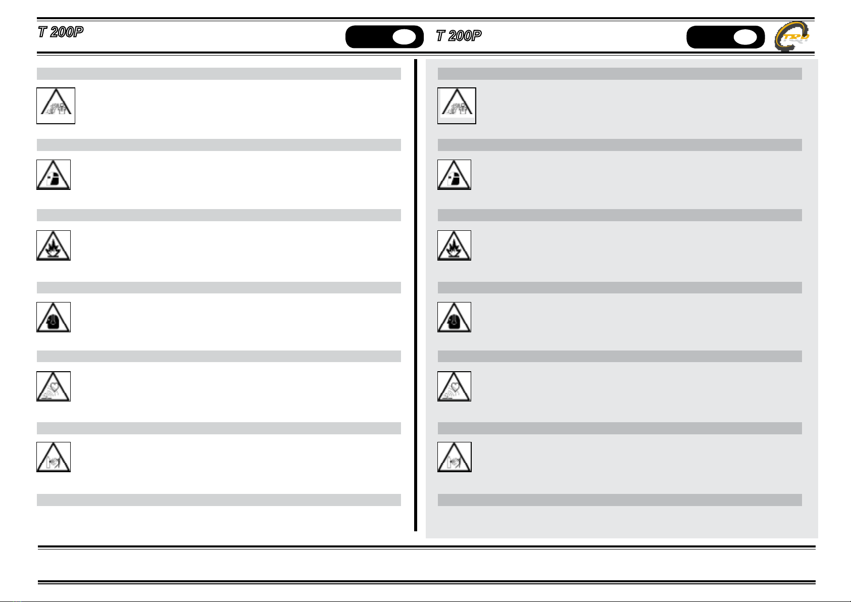
2. PRECAUZIONI DI SICUREZZA
L’arco elettrico generato in saldatura o taglio può essere dannoso per se stessi e per gli altri.
L’operatore deve pertanto essere ben informato ed istruito circa i rischi e pericoli qui di segui-
to descritti e derivanti da operazioni di saldatura.
SHOCK ELETTRICO – Può essere fatale
Collegate la macchina all’impianto elettrico di alimentazione nel pieno rispetto
delle norme di sicurezza applicabili, assicurandovi preventivamente che l’im-
pianto stesso sia a norma e provvisto di messa a terra. Non toccate a mani nude
elementi conduttivi o potenzialmente conduttivi della macchina, cavi ed elettrodi
della stessa, ed evitate l’utilizzo di guanti ed indumenti bagnati. Isolatevi dal pavimento e dal
pezzo da saldare. Assicuratevi di operare in un ambiente e posizione sicuri.
IMPORTANT
BEFORE STARTING THE EQUIPMENT, READ THE CONTENTS OF THIS MA-
NUAL, WHICH MUST BE STORED IN A PLACE FAMILIAR TO ALL USERS FOR
THE ENTIRE OPERATIVE LIFE-SPAN OF THE MACHINE.THIS EQUIPMENT
MUST BE USED SOLELY FOR WELDING OPERATIONS.
1. Conformity declaration
The machines descripted in this manual, T 200P, must be used solely for professional
purposes in an industrial environment and they are manufactured in compliance
with the instructions contained in the harmonized standard EN50199 (electromagnetic
compatibility) and EN60974-1. In case of bad operation you demand the attendance of
qualied staff.
1.1 RAEE Norm
The symbol on the product or on its packaging indicates that this product may not be
treated as household waste. Instead it shall be handed over to the applicable collec-
tion point for the recycling of electrical and electronic equipment. By ensuring this
product is disposed of correctly, you will help prevent potential negative consequen-
ces for the environment and human health, which could otherwise be caused by inap-
propiate waste handling of this product. For more detailed information about recycling
of this product, please contact your local city ofce, your household waste disposal
service or the shop where you purchased the product.
2. SAFETY PRECAUTIONS
WELDING AND ARC CUTTING CAN BE HARMFUL TO YOURSELF AND OTHERS. The
user must therefore be educated against the hazards, summarized below, deriving
from welding operations.
ELECTRIC SHOCK – May be fatal.
Install and earth the welding machine according to the applicable
regulations. Do not touch live electrical parts or eletrodes with bare
skin, gloves or wet clothing. Isolate yourselves from both the earth
and the workpiece. Make sure your working position is safe.
1