10
2.1 General Description, Purpose and Features.
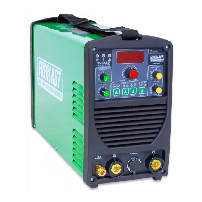
PowerARC 200STi:
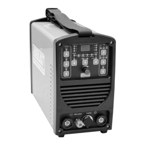
The PowerARC 200STi is a digitally controlled inverter welder
that provides DC stick and DC TIG welding capability (DC
SMAW/DC GTAW)wrapped up in a completely portable design.
The new digital design has allowed the incorporation of extra
features and improve overall performance. It has also im-
proved serviceability and reliability of the unit by reducing
internal circuitry and discrete structures. The welder is ideal
for welding tasks where portability and commercial perfor-
mance are required. With 120V/240V single phase capability,
the unit can be operated almost anywhere a power outlet is
found, and can be used with small clean powered generators
rated for at least 9000 surge watts (240V). (USA/Canada mod-
els only. Other regions may vary.)
Stick Features.
The improved Stick arc performance of the PowerARC 200STi
still includes the ability to weld with E6010/Cellulose rod type
as well as the ability to weld with almost any other type of
welding rod with a simple touch of a button. The smooth and
stable Stick welding characteristics of the PowerARC series are
well known, particularly with iron powder type rods. The
PowerARC 200STi no longer requires a separate work clamp
connector to select E6010 welding performance. However,
activation of the E6010 function on this welder only requires a
simple touch of a button to attain the crisper, more driving arc
performance that is needed to weld with cellulosic rods such as
the E6010, E6011, etc. The addition of adjustable arc force
control, hot start intensity and duration further renes the per-
formance of the machine with all welding rods. Adjustable Hot
start in stick mode reduces rod sticking while striking an arc by
providing a controlled surge of amps to temporarily increase
welding wattage. Similarly, the adjustable arc force controls
the intensity of the amp reaction to the arc length and by
providing extra current to the arc when the arc length is short-
ened and voltage begins to fall below 20 volts. This prevents
the arc from extinguishing and helps to improve overall arc
performance in all position welds by increasing amps to main-
tain a level welding wattage (Remember: Volts x Amps =
Watts).
TIG Features.
Additionally the unit has been improved in TIG function. The
low contamination Live lift function provides a continuously live
arc and allows the arc to be struck without the use of a foot
pedal or torch switch. With the version of live lift that the
PowerARC 200STi uses, the torch will always remain live, and
when contact is sensed, the current is lowered to allow an
easier time of lifting the torch without the tungsten sticking fast
in the target weld area. The torch is simply placed on the met-
al and lifted up to start the arc. Then the current automatically
increases to the set welding amperage once contact is broken.
The disadvantage is that the Tungsten is live all the time and
an arc could be accidentally struck, causing eye flash, burn or
serious injury. Careful attention to placement of the torch after
the arc has been terminated is required. The new improved
Live Lift TIG Start function provides a relatively clean, interfer-
ence free start for electronically sensitive areas where high
frequency (HF) arc starting is restricted or prohibited.
NOTE: This unit is DC output only. This unit is not intended to
TIG weld aluminum or magnesium. However, the unit can be
used to stick weld aluminum with specially designed aluminum
stick welding electrodes (rods). Flux-coated aluminum stick
welding rods are expensive. Other than occasional use for
emergency repair, are not generally considered a economically
viable alternative to AC TIG welding or MIG welding aluminum.
While DC+ and DC– TIG have both been used to weld alumi-
num in the past, both have technical and practical issues. AC
TIG is generally considered to be far superior, and is generally
considered by professionals the best method of welding alumi-
num.
2.2 Basic Overview and operation.
Basic Welding Package. The PowerARC 200STi package in-
cludes a basic stick welding package as standard equipment.
This is not a complete TIG and stick package. The TIG torch
and regulator will need to be purchased separately. The TIG
torch, if purchased from Everlast, will need to be congured to
work with the optional Regulator. The additional connector(s)
are not provided. The TIG torch can be connected via a 5/8” RH
female to female CGA coupling which is standard in the USA
and Canada. An additional male 5/8” CGA male to 1/4” hose
barb tting will need to be tted to the the torch to couple the
torch to the coupling. This will mean that the user will need to
remove and replace the existing tting on the torch. The ttings
are not supplied to do this. However, the ttings needed are
available from most local welding supply stores and online
welding supply sources. If this is not available, the same thing
may be accomplished with similar brass gas ttings available
from most hardware stores, but will also require retting the
regulator tting to match up. Some other brands may include a
5/8” RH male tting on the torch. In this case, only the cou-
pling will need to be purchased. If a TIG torch is required, the
suggested TIG torch is a 17V series for best combination of
flexibility and heat handling ability. A 26V torch is recom-
mended if you expect to regularly weld over 150 Amps. A TIG
torch with 12.5 ft. cables and DINSE 35/50mm² connector and
built-in gas valve is required for use regardless of series or
amp handling capability. Any of the 17, 26, or 18 series con-
sumables are compatible across the industry and are not
“special” or exclusive to Everlast. The gas regulator is optional
as well. The unit also includes a pigtail adapter for adapting the
unit to operate on 120V. No changeover other than the pigtail
adapter is needed to operate on 120V power.
The PowerARC 200STi package includes a stick welding pack-
age as standard equipment with an additional TIG torch and
accessory package available as an option. The stick package
includes a stick electrode holder with cable, and a work clamp
with cable. Work clamp and electrode cables are approximately
10 ft. in length. Longer cables lengths can be added to the
electrode holder and work clamp and accompanying 35/50mm²
connectors, if desired. These can be readily sourced at almost
any local welding supply store. Do not surpass 50 ft. lengths
General Setup and OperationSection 2
