SICE S 605 User manual

MANUALE ISTRUZIONI
MANUALE ISTRUZIONI
INSTRUCTION MANUAL
INSTRUCTION MANUAL
MANUEL D'INSTRUCTIONS
BETRIEBSANLEITUNG
BETRIEBSANLEITUNG
MANUAL DE INSTRUCCIONES
I
GB
F
D
E
EQUILIBRATRICE A CARRELLO • ON-THE-CAR WHEEL BALANCER
EQUILIBREUSE ROUE MONTEE FINISHBALANCER
EQUILIBRADORA SOBRE RUEDAS

2 -
S 605
DICHIARAZIONE CE DI CONFORMITA'
CE DECLARATION OF CONFORMITY
DECLARATION CE DE CONFORMITE
CE -KONFORMITÄTSERKLÄRUNG
DECLARACION CE DE CONFORMIDAD
SOCIETÀ ITALIANA COSTRUZIONI ELETTROMECCANICHE - S.I.C.E. S.p.A.
via Modena, 34 - 42015 Correggio (RE) ITALY
DICHIARA SOTTO LA SUA ESCLUSIVA RESPONSABILITA' CHE IL PRODOTTO AL QUALE QUESTA DICHIARAZIONE SI RIFERISCE E' CONFORME A QUANTO PREVISTO DALLE DIRETTIVE:
89/392/CEE (modificata con le direttive 91/368/CEE, 93/44/CEE e 93/68/CEE) e 89/336/CEE (modificata con la direttiva 92/31/CEE).
Norme di riferimento : EN 292 /1991 - EN 60204-1/1992
DECLARE ON ITS OWN RESPONSIBILITY THAT THE PRODUCT TO WHICH THIS DECLARATION REFERS IS IN CONFORMITY WITH THE DIRECTIVES: 89/392/EEC (amended with
directives 91/368/EEC, 93/44/EEC and 93/68/EEC) and 89/336/EEC (amended with directive 92/31/EEC).
Reference norms : EN 292 / 1991 - EN 60204-1/ 1992
DECLARE SOUS SA RESPONSABILITE PLEINE ET ENTIERE QUE LE PRODUIT VISE PAR CETTE DECLARATION EST CONFORME AUX PRESCRIPTIONS DE LA DIRECTIVE 89/392/CEE
(modifiée avec les directives 91/368/CEE, 93/44/CEE et 93/68/CEE) et 89/336/CEE (modifiée avec la directive 92/31/CEE).
Normes de référence: EN 292 / 1991 - EN 60204-1/1992
ERKLÄRT UNTER IHRER ALLEINIGEN VERANTWORTUNG, DIE KONFORMITÄT DES ERZEUGNISSES AUF DIE DIESE ERKLÄRUNG SICH BEZIEHT, MIT DEN BESTIMMUNGEN DER RICHTLINIE 89/
392/EWG (mit der Richtlinien 91/368/EWG, 93/44/EWG und 93/68/EWG modifiziert) und 89/336/EWG (mit der Richtlinien 92/31/EWG modifiziert)
Bezugsnormen: EN 292 / 1991- EN 60204-1 / 1992
DECLARA BAJO SU EXCLUSIVA RESPONSABILIDAD QUE EL PRODUCTO AL CUAL ESTA DECLARACION SE REFIERE ES CONFORME A LO PREVISTO POR LAS DIRECTIVAS 89/392/
CEE (modificada segun las directivas 91/368/CEE, 93/44/CEE y 93/68/CEE) y 89/336/CEE (modificada segun la directiva 92/31/CEE).
Normas de referencia: EN 292 / 1991 - EN 60204-1 / 1992
Equilibratrice a carrello, modello
On-the-car wheel balancer, model
Equilibreuse roue montée, modèle
Finishbalancer, modell
Equilibradora sobre ruedas, modelo
Il modello della presente di-
chiarazione è conforme a
quanto previsto nella EN
45014
The form of this statement
conforms to EN 45014
specifications.
Le modèle de la présente
déclarationestconformeàce
quiestprevuparlaNormeEN
45014
Das Formular dieser
Bestätigung entspricht den
BestimmungenderEN45014
El modelo de la presente
declaracion es conforme a
cuanto està previsto en las
especificacaiones EN 45014
Correggio, 01 - 02 - 2000
per S.I.C.E. S.p.A.
Giuliano Vignoli
TARGHETTA
TARGHETTA
MATRICOLA
MATRICOLA

S 605
- 3
4/5
4/5
4/5
6/7
6/7
8/9
8/9
10/11
12/13
12/13
12/13
12/13
16/17
16/17
16/17
20/21
22/23
22/23
26/27
26/27
26/27
28/29
28/29
28/29
28/29
30/31
30/31
SOMMARIO INDEX SOMMAIRE INHALT INDICE
1 - ALLGEMEINES
2 - TECHNISCHE DATEN
3 - SICHERHEITSBESTIMMUNGEN
4 - INSTALLATION
4.1 Transport und Lagerhaltung
4.2 Auspacken
4.3 Elektrischer Anschluß
5 - KENNZEICHNUNG DER
WARNSIGNALE
5.1
Zeichenerklärung der Warnsignale
6 -
DARSTELLUNG DER
WICHTIGSTEN MASCHINENTEILE
7 - BENUTZUNG
7.1
Funktion der Schaltblendentasten
7.2 Standardauswuchten
- Anordnung der Messwertnehmer
- Messlauf
- Sebstkalibration
- Anbringen der Ausgleichgewichten
7.3 Gleichzeitiges Auswuchten
der Zwei Triebräder
7.4 Schwellenwert
7.5 Empfindlichkeitseinstellung
von Hand
7.6 Laufrolle
7.7 Fehlermeldungen
8 - WARTUNG
9 - NICHTBENUTZUNG
10 -VERSCHROTTEN
11 - DATEN DES TYPENSCHILDS
12 - FEHLERSUCHE
1 - GENERALITES
2 -
CARACTERISTIQUES TECHNIQUES
3 - NORMES DE SECURITE
4 - INSTALLATION
4.1 Transport et stockage
4.2 Deballage
4.3 Raccordement electrique
5 - IDENTIFICATION DES SIGNAUX
DE DANGER
5.1
Légende des signaux de danger
6 - REPRESENTATION DES PIECES
FONCTIONNELLES
7 - UTILISATION
7.1
Fonction touches du panneau
7.2 Equilibrage standard
- Positionnement des pick-up
- Lancement
- Autoetalonnage
- Application des masses
7.3 Equilibrage simultane des
deux roues motrices
7.4 Seuil
7.5 Reglage manuel de la
sensibilité
7.6 Roue pivotante
7.7 Messages affiches sur visu
8 - ENTRETIEN
9 - REMISAGE
10 - MISE A DECHARGE
11 - PLAQUE SIGNALETIQUE
12 - INCONVENIENTS-CAUSES-
REMEDES
1 - GENERALIDADES
2 - CARACTERISTICAS TECNICAS
3 - NORMAS DE SEGURIDAD
4 - INSTALACION
4.1 Transporte y almacenamiento
4.2 Desembalaje
4.3 Conexion electrica
5 - IDENTIFICACION DE SEÑALES
DE PELIGRO
5.1
Leyenda se
ñales de peligro
6 - REPRESENTACION DE LAS
PARTES FUNCIONALES
7 - UTILIZACION
7.1 Funcion teclas del panel
7.2 Equilibrado estandar
- posicionamiento de los pick-up
- lanzamiento
- autocalibrado
- aplicacion contrapesos
7.3 Equilibrado simultaneo de las
dos ruedas motrices
7.4 Umbral
7.5 Fijacion manual de la
sensibilidad
7.6 Rueda pivote
7.7 Tabla mensajes visor
8 - MANTENIMIENTO
9 - ALMACENADO
10 - ENVIO AL DESGASTE
11 - DATOS DE MATRICULA
12 - INCONVENIENTES-CAUSAS-
REMEDIOS
1 - GENERAL INFORMATION
2 - TECHNICAL DATA
3 - GENERAL SAFETY REGULATIONS
4 - INSTALLATION
4.1 Transport and handling
4.2 Unpacking
4.3 Electrical connection
5 - IDENTIFYING WARNING
SIGNALS
5.1 Key to warning labels
6 - LAYOUT OF FUNCTIONAL
PARTS
7 - OPERATION
7.1 Panel function keys
7.2 Standard balancing
- positionning the pick-up
- spin
- self-calibration
- attaching the weights
7.3 Balancing 2WD at the same
time
7.4 Threshold
7.5 Setting sensivity manually
7.6 The castor
7.7 Table of display message
8 - MAINTENANCE
9 - STORING
10 - SCRAPPING A MACHINE
11 - DATA ON SERIAL PLATE
12 - TROUBLE SHOOTING
1 - GENERALITA'
2 - CARATTERISTICHE TECNICHE
3 - NORME DI SICUREZZA
4 - INSTALLAZIONE
4.1 Trasporto e stoccaggio
4.2 Disimballo
4.3 Collegamento elettrico
5 - IDENTIFICAZIONE SEGNALI
DI PERICOLO
5.1 Legenda segnali di pericolo
6 - RAPPRESENTAZIONE DELLE
PARTI FUNZIONALI
7 - USO
7.1 Funzione tasti del pannello
7.2
Equilibratura standard
- posizionamento dei pick-up
- lancio
- autotaratura
- applicazione dei contrappesi
7.3 Equilibratura contemporanea
delle due ruote motrici
7.4 Soglia
7.5 Impostazione manuale della
sensibilità
7.6 Ruota pivotante
7.7 Tabella messaggi errore
8 -MANUTENZIONE
9 - ACCANTONAMENTO
10 - ROTTAMAZIONE
11 - DATI DI TARGA
12 - INCONVEN.-CAUSE-RIMEDI

4 -
S 605
GENERALITA'
1
L'equilibratrice SICE S 605 è una macchina realizzata per
l'equilibratura di ruote di autovettura e veicoli industriali leg-
geri, direttamente sul veicolo.
Qualsiasi altro utilizzo è da ritenersi improprio e quindi irragio-
nevole e non consentito.
Prima di iniziare qualsiasi tipo di operazione è INDISPENSABILE
leggere e capire quanto riportato su questo manuale.
La S.I.C.E. S.p.A. non può essere ritenuta responsabile di danni
causati dall'uso improprio ed irragionevole delle sue attrezza-
ture.
CONSERVARE CON CURA QUESTO MANUALE PER OGNI ULTE-
RIORE CONSULTAZIONE.
E' possibile ottenere una copia del presente manuale specifi-
cando il modello e la matricola della apparecchiatura a cui si
riferisce e/o indicando il codice riportato sul retro di copertina.
GENERAL INFORMATION
1
The SICE S 605 has been designed to balance car and light
commercial van wheels directly on the veicle.
Any other use is improper and therefore not authorized. Before
beginning any kind of work on or with this machine, carefully
read and understand the contents of these operating instruc-
tions.
SICE Spa shall not be liable for any injury to persons or damage
to things caused by improper use of this machine.
KEEP THIS MANUAL TO HAND FOR EASY FUTURE CONSULTATION.
A copy of this manual can be obtained from manufacturer by
specifying lift model and serial number or by quoting the
ordering code number on the back of the cover.
L'uso dell'apparecchiatura è consentito solo a personale ap-
positamente addestrato ed autorizzato.
Il personale addetto deve leggere ed essere in grado di capire
quanto riportato sul presente manuale.
NORME DI SICUREZZA
3
This device may only be used by specifically trained and
authorised personnel. The operator must have read and fully
understood all the contents of this instruction manual.
GENERAL SAFETY REGULATIONS
3
2
CARATTERISTICHE TECNICHE
Alimentazione trifase
Potenza motore
Sensibilità di lettura
Tempo di lancio medio (con ruota 5"x14")
Velocità di equilibratura
Peso max. della ruota
Peso
Livello di press. acustica al posto di lavoro
Portata Pick Up PU 700 C
Peso Pick Up PU 700 C
Portata Pick Up PU 3500 T
Peso Pick Up PU 3500 T
2
TECHNICAL DATA
3-Phase power supply
Motor power
Balancing accuracy
Avarage spin time (with 5x14" wheel)
Balancing speed
Max. wheel weight
Weight
Acoustic pressure level (at work)
Capacity Pick Up PU 700 C
Weight Pick Up PU 700 C
Capacity Pick Up PU 3500 T
Weight Pick Up PU 3500 T
220-380-415V. 50/60 Hz.
3,7-4,7 kW
1 gr.
5 sec.
150 km/h
65 kg
120 kg
LpA < 70 dB (A)
700 kg.
22 kg.
3500 kg.
37 kg.
220-380-415V. 50/60 Hz.
3,7-4,7 kW
1 grammo
5 sec.
150 km/h.
65 kg
120 kg
LpA < 70 dB (A)
700 kg.
22 kg.
3500 kg.
37 kg.

S 605
- 5
GENERALITES
1
L’équilibreuse S 605 est une machine réalisée pour
l’équilibrage de roues de voiture et de véhicules industriels
légers, directement sur le véhicule.Toute autre utilisation est
impropre et donc non autorisée
Avant d’effectuer une opération quelconque il est
INDISPENSABLE de lire et comprendre les instructions de ce
manuel.
S.I.C.E. S.p.A. ne répond pas des dommages provoqués par
une utilisation impropre de ses équipements.
CONSERVER AVEC SOIN CE MANUEL POUR TOUTE
CONSULTATION ULTERIEURE.Il est possible d’obtenir une copie
du présent manuel en indiquant le modèle et le matricule de
l’appareillage ou en indiquant le code imprimé au dos de la
page de couverture.
ALLGEMEINES
1
Die Auswuchtmaschine SICE S 605 ist eine Maschine, die zum
Auswuchten von Pkw- und Llkw-Rädern direkt am Fahrzeug
entwickelt worden ist.
Jede andere Verwendung ist als nicht bestimmungsmäßig zu
betrachten und daher nicht genehmigt.
Bevor man mit der Maschine arbeitet, ist es UNABDINGBAR, den
Inhalt dieses Handbuchs gelesen und verstanden zu haben.
Firma SICE S.p.A. haftet nicht für Schaden, der durch die
unzweckmäßige Benutzung dieser Maschine entsteht.
BEWAHREN SIE DIESES HANDBUCH SORGFÄLTIG AUF UND
BENUTZEN ES BEI DER BEDIENUNG DER MASCHINE.
Es ist möglich, eine Kopie dieses Handbuchs zu erhalten, wenn
Sie das Modell und die Seriennummer der Maschine angeben,
auf die Sie sich beziehen, oder wenn Sie die Code-Nr. angeben,
die auf der Umschlagrückseite dieses Handbuchs steht.
GENERALIDADES
1
La equilibradora SICE S 605 es una máquina ideada para el
equilibrado de ruedas de automóviles y vehículos industriales
livianos, directamente sobre el vehículo.
Cualquier otro uso es impropio y por tanto irracional y no
permitido. Antes de comenzar cualquier tipo de operación es
indispensable leer y comprender cuanto muestra estas
instrucciones.
La S.I.C.E. S.p.A. no puede ser considerada responsable de
daños causados por el uso impropio e irracional de sus equipos.
CONSERVAR CON CUIDADO ESTE MANUAL PARA CUALQUIER
CONSULTA ULTERIOR. Es posible obtener una copia del presen-
te manual especificando el modelo y la matrícula del equipo
al cual se refiere y/o indicando el código expuesto en el revés
de la portada.
L’utilisation de l’appareillage est réservée au personnel
spécialement formé et autorisé. Le personnel préposé doit
lire et être en mesure de comprendre ce qui est indiqué dans
ce manuel d’instructions.
NORMES DE SECURITE
3
Die Benutzung dieses Geräts ist für speziell ausgebildetes Per-
sonal mit einer Genehmigung dafür reserviert. Das mit der
Benutzung der Maschine betraute Personal muß dieses
Handbuch lesen und in der Lage sein, den Inhalt zu verstehen.
SICHERHEITSBESTIMMUNGEN
3NORMAS DE SEGURIDAD
3
El uso del equipo está permitido solo a personal adiestrado a
propósito y autorizado. El personal específico debe leer y ser
capaz de entender lo expuesto en el presente manual.
2
CARACTERISTIQUES TECHNIQUES
Alimentation triphasée
Puissance moteur
Sensibilité de lecture
Temps moyen de lancem. (avec roue 5"x14")
Vitesse d’équilibrage
Poids maxi. de la roue
Poids
Niveau sonore au poste de travail
Charge utile du Pick-up 700 C
Poids du Pick Up PU 700 C
Charge utile du Pick-up PU 3500 T
Poids du Pick Up PU 3500 T
220-380-415V. 50/60 Hz.
3,7-4,7 kW
1 gr.
5 sec.
150 km/h.
65 kg
120 kg
LpA < 70 dB (A)
700 kg.
22 kg.
3500 kg.
37 kg.
2
TECHNISCHE DATEN
220-380-415V. 50/60 Hz
3,7-4,7 kW
1 g
5 sec
150 km/h
65 kg
120 kg
LpA < 70 dB (A)
700 kg
22 kg
3500 kg
37 kg
Dreiphasiger Stromversorgung
Motorleistung
Empfindlichkeit des Ablesung
Durchschnittliche Laufzeit (mit Rad 5"x14")
Auswuchtgeschwindigkeit
Max. Radgewicht
Gewicht
Schalldruckpegel am Arbeitsplatz
2
CARACTERISTICAS TECNICAS
220-380-415V. 50/60 Hz.
3,7-4,7 kW
1 gr.
5 seg.
150 km/h.
65 kg
120 kg
LpA < 70 dB (A)
700 kg.
22 kg.
3500 kg.
37 kg.
Alimentación trifásica
Potencia motor
Sensibilidad de lectura
Tiempo lanzamiento medio (con rueda 5"-14")
Velocidad equilibrado
Peso m
áximo de la rueda
Peso
Nivel de presión acúst. en el puesto de trabajo
Belastbarkeit Meßwertnehmer 700 C
Gewicht Meßwertnehmer 700 C
Belastbarkeit Meßwertnehmer 3500T
Gewicht Meßwertnehmer 3500 T
Cap. carga Pick Up PU 700 C
Peso Pick Up PU 700 C
Capac. carga Pick Up 3500 T
Peso Pick Up PU 3500 T

6 -
S 605
A
kg. 150
4 4
La macchina è fornita in una cassa in legno con pallet, di
dimensione 870 x 970mm. x h. 940mm.
La equilibratrice S 605 va trasportata e tenuta a magazzino con
imballo originale integro.
CONDIZIONI PER LO STOCCAGGIO:
Deve essere movimentata per mezzo di un fork-lift posizionan-
do le lame nei punti indicati in figura A.
Il peso della macchina imballata è di 150 Kg.
The machine is delivered in a wooden crate with pallet
(dimensions: 870 x 970mm. x h. 940mm.).
The S 605 wheel balancer should be transported and stored in
its original packing.
CONDITION IN PLACE OF STORAGE:
It must be moved using a fork-lift truck with the forks positioned
as shown in picture A.
Shipping weight is 150 kg.
INSTALLAZIONE INSTALLATION
E' comunque indispensabile:
- Conoscere ed applicare le normative vigenti nel proprio
paese per quanto riguarda il comportamento e la sicurezza sul
lavoro.
- Utilizzare la presente apparecchiatura secondo le caratteristi-
che e le capacità elencate su questo manuale.
-Nonoperaremaitrasgredendoleistruzionid'usoedimanuten-
zione relative all'apparecchiatura.
- Durante le operazioni tenere le mani e le altre parti del corpo
il più lontano possibile dalle parti in movimento. Collane, brac-
cialetti, abiti non aderenti, costituiscono pericolo per chi opera
e non debbono essere indossati.
- Accertarsi che nessuno, tranne il personale autorizzato all'uso
dell'apparecchiatura, sia nelle immediate vicinanze mentre
questa é operativa.
- Non appoggiare mai sull'apparecchiatura viti, dadi, utensili,
stracci o altri oggetti che durante le fasi di lavoro potrebbero
inserirsi tra le parti in movimento della stessa.
- Qualsiasi manomissione o modifica dell'apparecchiatura non
preventivamente autorizzata dal costruttore solleva quest'ulti-
mo dai danni causati o riferibili agli atti suddetti.
In any event it is essential that the operator:
- Knows and applies the current regulations in force in his country
covering worker behaviour and safety matters in the workshop.
- Uses this device in compliance with the specifications and
performance parameters listed in this
manual.
- Observe the operating and maintenance instructions when
using the device.
- When working with the machine keep hand and other parts
of the body as far away as possible from moving parts.
Necklaces, bracelets, hanging garments are dangerous when
you work, don't use it.
- Checks to make sure that nobody, apart from authorised
operators, in the immediate area of the device when it is being
used.
- Never puts screws, nuts, tools, rags, etc. on the device that
could fall into moving parts when it
is being used.
- Any tampering with or modification to the device not
authorised in advance by manufacturer, releases the same from
any liability for injury to
persons or damage to property caused by such
actions.
Umidità relativa
Temperatura
20% - 95%
-10°C e +60°C
Relative humidity
Temperatura
20% - 95%
-10
°
C e +60
°
C
4.1 4.1
TRASPORTO E STOCCAGGIO TRANSPORT AND HANDLING

S 605
- 7
44 4
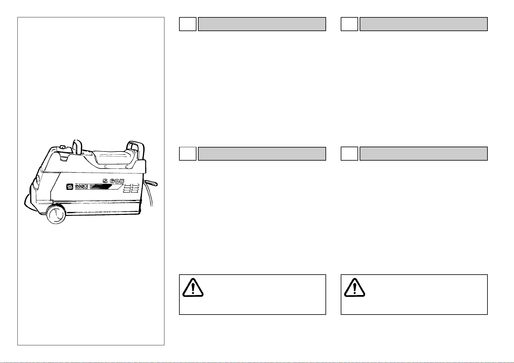
La machine est fournie dans une caisse en bois sur palette dont
les dimensions sont 870 x 970 x 940 mm h. Die Maschine wird in einer Holzkiste auf Palette geliefert. Die
Größe der verpackten Maschine beträgt: LxBxH = 870 x 970 x
940 mm.
La máquina se suministra en un cajón de madera con pallet,
de dimensión 870 x 970 mm x h. 940 mm.
INSTALACIONINSTALLATION INSTALLATION
Es ist auf jeden Fall unabdingbar, daß der Bediener:
- die in seinem Land geltenden Bestimmungen kennt und
anwendet, was das Verhalten und die Sicherheit am Arbeitsplatz
betrifft.
- diese Maschine gemäß der Merkmale und der Fähigkeiten
benutzt, die in diesem Handbuch beschrieben sind.
- bei der Arbeit nie die Vorschriften zur Bedienung und Wartung
der entsprechenden Maschine mißachtet.
- während der Arbeitsvorgänge die Hände und die anderen
Körperteile so weit wie möglich entfernt von den sich
bewegenden Teilen der Maschine hält. Halsketten, Armbänder,
nicht eng anliegende Kleidungsstücke stellen eine
Gefahrenquelle für den Bediener der Maschine dar und dürfen
nicht getragen werden.
- sicherstellt, daß während des Betriebs neben dem
Maschinenbediener keine weiteren Personen in der
unmittelbaren Nähe der Maschine stehen.
- nie Schrauben, Muttern, Werkzeuge, Lappen oder andere
Gegenstände während der Arbeit auf der Maschine ablegt, weil
diese zwischen die laufenden Maschinenteile geraten könnten.
- Jede Manipulation oder Änderung der Maschine, die nicht
vorher vom Hersteller genehmigt worden ist, enthebt diesen von
der Haftung für Schäden, die dadurch verursacht werden oder
sich darauf zurückführen lassen.
Es de todos modos indispensable:
- Conocer y aplicar las normativas vigentes en el propio país
en lo relativo al comportamiento y la seguridad en el trabajo.
- Usar el presente equipo según las características y las
capacidades enumeradas en este manual.
- No operar nunca transgrediendo las instrucciones de uso y
de mantenimiento relativas al equipo.
- Durante las operaciones mantener las manos y las restantes
partes del cuerpo lo más lejos posible de las partes en
movimiento. Collares, brazaletes, ropa amplia, constituyen un
peligro para quien opera con el equipo y no deben ser por lo
tanto usados.
- Cerciorarse que ninguno, excepto el personal autorizado al
empleo del equipo, se encuentre en las cercanías mientras
este último está funcionando.
- No apoyar nunca sobre el equipo, tornillos, tuercas,
herramientas, trapos ni otros objetos que durante las fases de
trabajo podrían introducirse entre las partes en movimiento del
equipo.
- Toda adulteración o modificación del equipo no autorizada
previamente por el fabricante exime este último por los daños
causados o derivantes de dichos actos.
Humidité relative
20% - 95%
-10°C e +60°C
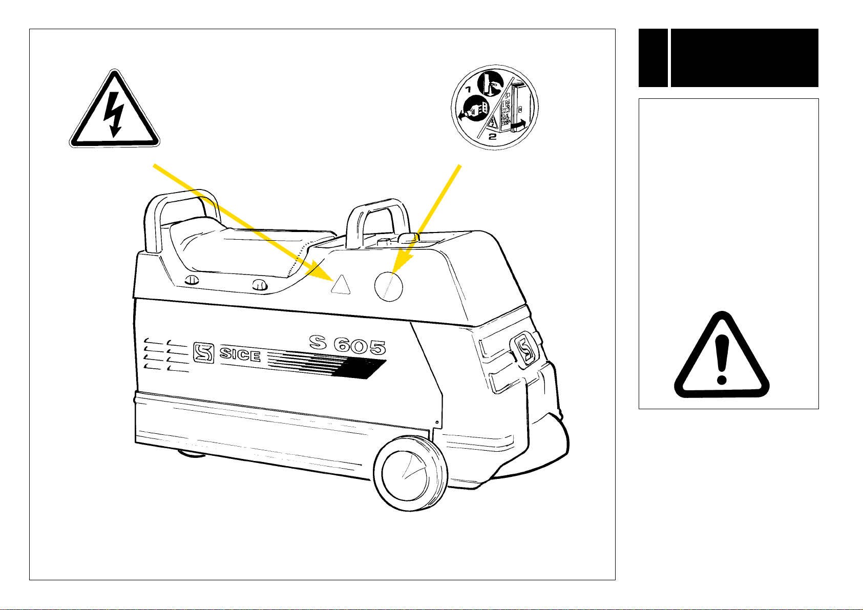
Die Kiste ist mit einem Gabelstaplerzu bewegen, der an den
Stellen ansetzt, die in der Abbildung Agezeigt sind.
Das Gewicht der verpackten Maschine beträgt 150 kg.
20% - 95%
-10
°
C e +60
°
C
Humedad relativa
20% - 95%
-10°C e +60°C
TRANSPORT ET STOCKAGE
4.1 TRANSPORT UND LAGERHALTUNG
4.1
TRANSPORTE Y ALMACENAMIENTO
4.1
Der Transport und die Lagerhaltung der Auswuchtmaschine
S 605 sind in der Originalkiste vorzunehmen.
BEDINGUNGEN DER LAGERHALTUNG:
Relative Feuchte
Temperatur
Obligation de l’opérateur :
- Connaître et appliquer les normes en vigueur dans son propre
pays en ce qui concerne le comportement et la sécurité sur le
travail.
- Utiliser le présent appareillage suivant les caractéristiques et
les capacités énoncées dans ce manuel.
- Ne jamais travailler en contrevenant aux instructions
d’utilisation et d’entretien relatives à l’appareillage.
- Pendant les opérations tenir les mains et les autres parties du
corps le plus loin possible des parties en mouvement. Les colliers,
bracelets, vêtements flottants, constituent un danger pour
l’opérateur.
- S’assurer que personne, à part le personnel autorisé à
l’utilisation de l’appareillage, ne se trouve à proximité quand
celle-ci est en marche.
- N’appuyer jamais sur l’appareillage des vis, écrous, outils,
chiffons ou autres objets pouvant s’encastrer dans les parties
en mouvement pendant les phases de travail.
- Toute manipulation ou modification de l’appareillage sans
autorisation préalable du constructeur décharge ce dernier
dans le cas de dommages attribuables à ces actes.
Température
L’équilibreuse S 605 doit être transportée et tenue en magasin
avec l’emballage original intégral.
CONDITION POUR LE STOCKAGE:
Doit être manutentionnée avec un chariot élévateur en
plaçant les fourches dans les points indiqués dans la figure A.
Le poids de la machine emballée est de 150 kg.
La equilibradora S 605 debe ser transportada y depositada en
el almacén con su embalaje original íntegro.
CONDICIONES PARA EL ALMACENAMIENTO:
Temperatura
Debe ser manipulada con una carretilla elevadora
posicionando las horquillas en los puntos indicados en la fig. A.
El peso de la máquina embalada es de 150 Kg.

8 -
S 605
L'Imballo contiene:
n°1 Equilibratrice S 605
n°1 Scatola accessori in dotazione
n°1 Manuale di istruzioni d'uso
Dopo aver tolto l'imballaggio assicurarsi dell'integrità dell'ap-
parecchiatura controllando che non vi siano parti danneggia-
te.
- In caso di anomalie riscontrate o dubbi sullo stato dell'appa-
recchiatura, non procedere all'uso e rivolgersi immediatamen-
te al rivenditore.
- Gli elementi dell'imballaggio non devono essere lasciati alla
portata dei bambini in quanto potenziali fonti di pericolo.
- Conservare l'imballo per eventuali trasporti futuri.
Paking includes:
n
°
1 S 605 wheel balancer
n
°
1 Carton box with standard accessories
n
°
1 Instruction manual
Once the packing material has been removed, check the
machine visually for any signs of damage.
- If you note faults in the equipment or have doubts about its
status, do not use it but contact your nearest Sice Dealer
immediately.
- Keep the packing material out of the reach of children as it
can be a source of danger.
- Keep the packing for possible future transport.
La macchina, in versione standard, è predisposta per essere
collegata a 380V. trifase 50Hz., e viene fornita completa di
spina a norme CE.
Diverse alimentazioni vanno specificate al momento dell'ordi-
ne. Prima di effettuare qualsiasi collegamento elettrico control-
lare attentamente che la tensione di rete corrisponda con
quanto riportato sul cartellino voltaggio (posizionato in prossi-
mità della spina dell'equilibratrice).
E' assolutamente obbligatorio che l'impianto sia corredato di
una buona rete di terra.
La macchina deve essere collegata ad interruttore automatico
di alimentazione (differenziale) tarato a 30 mA.
Leggere sull'apposita targhetta situata sul retro dell'equilibratri-
ce, l'assorbimento richiesto e verificare se la rete elettrica in
questione è sufficientemente dimensionata.
The standard version of the machine is set up for 380V, 3-
phase 50 Hz power supply and comes complete with a plug
conforming to EU regulations.
Other power requirements should be specified with the order.
Before making the connections, check to be certain that the
mains supply voltage is the same as that shown on the voltage
tag (near the balancer’s plug).
The machine must be connected to an efficient grounding
circuit.
The machine must be connected to a circuit breaker set for
30mA.
Notethe power drawrequiredregistered on theplateattached
to the back of the balancer. Check the shop electric circuit to
be certain it matches this and is sufficiently sized.
Interventi sull'impianto elettrico, anche
di lieve entità, richiedono l'opera di
personale professionalmente qualific
ato.
Any work whatsoever, even minor, on the
electricsystemmustbedonebyprofessionally
qualified personnel.
Ogni danno derivante dalla mancata osservanza delle suddet-
te indicazioni non sarà addebitabile al costruttore e potrà
causare la decadenza delle condizioni di garanzia.
Any damage or injury caused by failure to observe these
indications shall not be charged to the Manufacturer and
can cancel the warranty coverage.
4.2 4.2
DISIMBALLO UNPACKING
4.3 4.3
COLLEGAMENTO ELETTRICO ELECTRICAL CONNECTION

S 605
- 9
DEBALLAGE
4.2
AUSPACKEN
4.2
DESEMBALAJE
4.2
RACCORDEMENT ELECTRIQUE
4.3 ELEKTRISCHER ANSCHLUSS
4.3
CONEXION ELECTRICA
4.3
Die Verpackung enthält:
1 Auswuchtmaschine S 605
1 Karton mit serienmäßigem Zubehör
1 Betriebsanleitung
Nachdem die Maschine aus der Verpackung herausgenommen wur-
de, eine Sichtkontrolle vornehmen, um festzustellen, ob sie keine
Schäden aufweist.
- Werden Schäden festgestellt oder es bestehen Zweifel zum Zustand
der Maschine, benutzen Sie diese nicht, sondern wenden sich sofort
an den Händler.
- Die Packteile dürfen nicht in der Reichweite von Kindern liegenge-
lassen werden, weil sie eine mögliche Gefahrenquelle darstellen.
- Die Packteile für mögliche künftige Transporte aufbewahren.
Die Maschine in der Standardausführung eignet sich für den An-
schluß an ein Stromnetz mit 380 V Drehstrom und 50 Hz. Sie wird
mit einem den EU-Bestimmungen entsprechenden Gerätestek-
ker ausgeliefert. Davon abweichende Stromanschlüsse sind schon
bei der Bestellung der Maschine anzufordern. Bevor der elektri-
sche Anschluß ausgeführt wird, aufmerksam prüfen, daß die Netz-
spannung mit dem Wert übereinstimmt, der auf dem Typenschild
der Maschine steht (in der Nähe des Gerätesteckers).
Es ist unbedingt erforderlich, daß die Anlage ordentlich geer-
det ist.
Die Maschine muß anein en Fehlerstromschalter angeschlos-
sen werden, der auf 30 mA eingestellt ist.
Auf dem Schild auf der Rückseite der Auswuchtmaschine die
erforderliche Stromaufnahme ablesen und sicherstellen, ob das
Stromnetz ausreichend groß ausgelegt ist.
Arbeiten an der elektrischen Anlage, auch
kleineren Umfangs, müsse durch
qualifiziertes Personal ausgeführt werden.
Alle Schäden, die sich aus der Nichtbeachtung der oben ste-
henden Vorschriften ergeben, lassen sich nicht dem Hersteller
zuschreiben, sondern können zum Verfall der Garantie führen.
L’emballage contient :
n°1 Equilibrage
n°1 Boîte d’accessoires en équipement
n°1 Manuel d’instructions d’utilisation
Après avoir enlevé l’emballage s’assurer du bon état de la
machine en vérifiant qu’il n’y a pas de parties visiblement
endommagées.
- En cas d’anomalies ou de doutes sur l’état de l’appareillage,
arrêter l’utilisation et contacter immédiatement le revendeur.
- Les éléments de l’emballage ne doivent pas être laissés à la
portée des enfants car ils représentent des sources de danger.
- Conserver l’emballage pour les éventuels transports futurs.
La machine, dans sa version standard, est prévue pour être
reliée à 380V, triphasé 50Hz, et elle est fournie avec une fiche
aux normes CE.
Nous vous prions de signaler les alimentations différentes au
moment de la commande. Avant d’effectuer un quelconque
raccordement électrique contrôler attentivement que la
tension du secteur correspond à ce qui est indiqué sur
l’étiquette placée près de la fiche de l’équilibreuse.
L’installation doit obligatoirement être munie d’une bonne mise
à la terre.
La machine doit être reliée à un interrupteur automatique
d’alimentation (différentiel) étalonné à 30 mA.
Lire l’absorption requise sur la plaque placée sur la partie arrière
de l’équilibreuse et vérifier si le réseau électrique en question
est dimensionné de manière suffisante.
Les interventions sur l’installation électrique,
même de faible importance, doivent être
effectuées par du personnel qualifié.
Tout dommage dérivant de l’inobservation de ces indications
ne sera pas imputable au constructeur et pourra entraîner la
déchéance de la garantie.
El embalaje contiene:
n°1 Equilibradora S 605
n°1 Caja accesorios de serie
n°1 Manual de instrucciones de uso
Luego de haber quitado el embalaje cerciorarse que el equipo esté
en perfecto estado controlando que no se presenten partes daña-
das.
- Si se advierten anomalías o tenemos dudas sobre el estado del
equipo, no usarlo y contactar inmediatamente el concesionario ven-
dedor.
- Los elementos del embalaje no deben ser abandonados al alcan-
ce de los niños ya que representan potenciales fuentes de peligro.
- Conservar el embalaje para eventuales transportes futuros.
La máquina, en su versión estándar, está preparada para ser
conectada a 380V trifásica 50 Hz, y se entrega con enchufe
según normas CE.
Otros tipos de alimentaciones deben ser especificadas en el
momento del pedido. Antes de efectuar cualquier conexión
eléctrica controlar atentamente que la tensión de red
corresponda con lo expuesto en la placa voltaje (presente
cerca del enchufe de la equilibradora).
Resulta taxativamente necesario que la instalación posea una
correcta conexión a tierra.
La máquina debe estar conectada a un interruptor automático
de alimentación (diferencial) regulado a 30 mA.
Leer en la relativa placa situada en la parte posterior de la
equilibradora la absorción requerida y controlar si la red
eléctrica en cuestión está correctamente dimensionada.
T
rabajos en la instalación eléctrica, incluso
mínimos, deberán estar a cargo de perso-
nal profesionalmente calificado.
Todo daño derivante del incumplimiento de las precedentes
indicaciones no podrá ser imputado al fabricante y podrá de-
terminar la pérdida de los términos de garantía.

10 -
S 605
IDENTIFICAZIONE
SEGNALI
DI PERICOLO
5
ATTENZIONE:
Nel caso le targhette di pericolo
risultino illeggibili o siano state ri-
mosse, sostituirle immediatamen-
te. Non utilizzare l'equilibratrice se
mancante di una o più targhette
di pericolo.
Non interporre oggetti che ne
ostruiscano la visione all'operato-
re.
Per eventuali richieste utilizzare il
codice indicato nella presente ta-
vola.
Code 9446598
Code 3005912

S 605
- 11
5
IDENTIFICATION DES
SIGNAUX DE
DANGER
5 5
WARNING:
Unreadable and missing warning
labels must be replaced immedi-
ately.
Do not use the wheel balancer if
one or more labels are missing.
Do not add any object that could
prevent the operator from seeing
the labels.
Use the code in this table to order
labels you need.
ATTENTION:
Si les plaques signalétiques de
danger sont peu lisibles ou si elles
ont été enlevées, les remplacer
immédiatement. Ne pas utiliser
l'équilibreuse si une ou plusieurs
plaques de danger sont man-
quantes.
Ne pas interposer des objets
pouvant cacher la vue à
l’opérateur.
Pour les commandes utiliser le
code indiqué sur cette illustration.
IDENTIFYING
WARNING SIGNALS
KENNZEICHNUNG
DER WARNSIGNALE
ACHTUNG:
Unleserlich gewordene oder
entfernte Warnschilder müssen
sofort ersetzt werden. Benutzen Sie
die Auswuchtmaschine nicht,
wenn eins oder mehrere
Warnschilder fehlen.
Keine Gegenstände anbringen,
die dem Bediener die freie Sicht
auf diese Schilder nehmen.
Für die etwaige Bestellung von
Schildern verwenden Sie die
Codezahlen dieser Abbildung.
5
ATENCION !
En caso de que las tarjetas de
peligro resulten ilegibles o hayan
sido quitadas, sustituirlas inmedia-
tamente.
No utilizar la equilibradora si falta
una o mas tarjetas de peligro. No
interponer objetos que obstruyan
la visión al operario.
Para eventuales pedidos utilizar el
código indicado en la presente
tabla.
IDENTIFICACION DE
SEÑALES DE PELIGRO

12 -
S 605
LEGENDA SEGNALI DI PERICOLO
5.1
Staccare la spina dalla presa di alimentazione prima di ese-
guire interventi di assistenza sulla macchina.
Pericolo: presenza tensione di rete.
KEY TO WARNING LABELS
5.1
Unplug the power supply cable before carrying out mainten-
ance work on the machine.
Danger: high voltage.
1 - Keyboard
2 - General switch
3 - Drive wheel
4 - Locking lever
6
LAYOUT OF FUNCTIONAL PARTS
(FIG. B)
1 - Tastiera
2 - Interruttore generale
3 - Puleggia
4 - Leva bloccaggio
6
RAPPRESENTAZIONE DELLE
PARTI FUNZIONALI (FIG. B)
1
3
2
4
B
1
2
3
4
5
6
911
10
7
8
C
ATTENZIONE!
Durante le operazioni tenere le mani e le altre parti
del corpo il più lontano possibile dalle parti
in movimento. Collane, braccialetti, abiti
non aderenti, possono costituire pericolo
per chi opera.
WARNING!
During all operations, keep hands and other parts
of the body as far as possible from moving
parts of the machine. Necklaces, bracelets
and too large clothes, can be dangerous
for the operator.
USO
OPERATION
77
Tasto ruota opposta (1, Fig. C)
Memorizza o richiama il valore di squilibrio della
ruota situata sul lato opposto rispetto
all'equilibratrice.
Tasto ruota di fronte (2, Fig. C)
Memorizza o richiama il valore di squilibrio della
ruota situata sul lato dell'equilibratrice.
Opposite wheel key (1, Fig. C)
Memorizes or recalls the unbalance for the wheel
opposite the one being balanced.
Balancing wheel key (2, Fig. C)
Memorizes or recalls the unbalance for the wheel
in front of the balancer currently being balanced.
7.1 7.1
FUNZIONE TASTI DEL PANNELLO PANEL FUNCTION KEYS

S 605
- 13
LEGENDE DES SIGNAUX DE DANGER
5.1
Débrancher la fiche d’alimentation avant toute intervention
d’entretien sur la machine.
Danger: présence de courant électrique.
ZEICHENERKLÄRUNG DER WARNSIGNALE
5.1
Vor der Ausführung von Wartungs- oder Service-Eingriffen an
der Maschine unbedingt das Stromkabel ziehen.
Gefahr: Netzspannung vorhanden.
LEYENDA SEÑALES DE PELIGRO
5.1
Desconectar la clavija de alimentación antes efectuar
intervenciones de asistencia en la máquina.
Peligro: presencia de tensión de red.
REPRESENTATION DES PIECES
FONCTIONNELLES (FIG. B)
DARSTELLUNG DER WICHTIGSTEN
MASCHINENTEILE (ABB. B)
6
1 - Tastatur
2 - Hauptschalter
3 - Antriebsscheibe
4 - Sperrhebel
1 - Clavier
2 - Interrupteur général
3 - Poulie
4 - Levier de blocage
3-
6
1 - Teclado
2 - Interruptor general
3 - Polea
4 - Palanca bloqueo
6
REPRESENTACION DE LAS
PARTES FUNCIONALES (FIG. B)
ATTENTION!
Pendant le travail tenir les mains et les autres parties
du corps le plus loin possible des parties
en mouvement. Les colliers, bracelets,
vêtements flottants, peuvent constituer un
danger pour l’opérateur.
ACHTUNG!
Während der Arbeit sind die Hände und andere
Körperteile so weit wie möglich weg von den
sich bewegenden Teilen zu halten.
Halsketten, Armbänder und weite Kleidung
können für den Bediener zur Gefahr werden.
ATENCION !
Durante las operaciones tener las manos y demás
partes del cuerpo lo más lejos posible de las
partes en movimiento. Collares, brazaletes,
ropas holgadas, pueden constituir peligro
para quien trabaje con la máquina
UTILISATION
BENUTZUNG
UTILIZACION
777
7.1
FUNKTION DER SCHALTBLENDENTASTEN
7.1 7.1
Taste gegenüberliegendes Rad (1 Abb. C)
Zum Speichern oder Aufrufen der Unwuchtwerte des
Rades, das sich im Bezug zur Auswuchtmaschine auf
der anderen Seite befindet.
Taste auszuwuchtendes Rad (2 Abb. C)
Zum Speichern oder Aufrufen der Unwuchtwerte
des Rades, das sich im Bezug zur
Auswuchtmaschine auf der gleichen Seite befindet.
FONCTIONS TOUCHES DU PANNEAU
Touche roue de face (2, Fig. C)
Mémorise ou rappelle la valeur de balourd de la
roue située sur le côté de l’équilibreuse.
FUNCION TECLAS DEL PANEL
Tecla Rueda Opuesta (1, Fig. C)
Memoriza o llama el valor de desequilibrio
de la rueda situada del lado opuesto respecto a
la equilibradora.
Touche roue opposée (1,Fig. C)
Mémorise ou rappelle la valeur de balourd de la
roue située sur le côté opposé par rapport à
l'équilibreuse.
Tecla Rueda De Frente (2, Fig. C)
Memoriza o llama el valor de desequilibrio de la
rueda situada del lado de la equilibradora
.

14 -
S 605
1
2
3
4
5
6
911
10
7
8
12
13 14 C
Tasto autotaratura (3, Fig. C)
Attiva la procedura di autotaratura sugli squilibri
della ruota.
Tasto x 10 (4, Fig. C)
Moltiplica per 10 il valore dello squilibrio, consen-
tendone una corretta visualizzazione quando si
utilizza il pick-up PU 3500T.
Tasto F (5, Fig. C)
Premuto 2 volte consecutive consente un reset
dell'equilibratrice.
Tasto RPM (6, Fig. C)
Visualizza il numero dei giri della ruota in esame.
Tasto soglia (7, Fig. C)
Consente di visualizzare squilibri inferiori ai 5
grammi.
Tasto sensibilità (8, Fig. C)
Consente di variare manualmente la sensibilità di
acquisizione.
Led ruota opposta (9, Fig. C)
Si accende quando la ruota, situata sul lato
opposto rispetto all'equilibratrice, ha raggiunto la
velocità necessaria per l'acquisizione.
Led ruota di fronte (10, Fig. C)
Si accende quando la ruota, situata sul lato
dell'equilibratrice, ha raggiunto la velocità
necessaria per l'acquisizione.
Led controllo velocità (11, Fig. C)
Si accende quando, operando contemporanea-
mente sulle ruote motrici, vi è una differenza di
velocità tra queste, superiore ai 150 giri/min.
Commutatore di velocità (12, Fig. C)
Consente di far girare la puleggia in un senso o
nell'altro e a 2 diverse velocità.
Pulsante START (13, Fig. C)
Mette in moto il motore (a commutatore inserito).
Pulsante STOP (14, Fig. C)
Spegne il motore e agisce sul freno elettromagne-
tico per fermare la ruota.
Self-calibration key (3, Fig. C)
Activates self-calibration based on the wheel
unbalance.
x 10 key (4, Fig. C)
Multiples the unbalance by a factor of 10 to
permit correct display when using the PU 3500T
pick-up.
F key (5, Fig. C)
When pressed twice, resets the balancer.
RPM key (6, Fig. C)
Display the rpm for the wheel being balanced.
Threshold key (7, Fig. C)
Permits display of unbalance below the 5 gr.
threshold.
Sensitivity key (8, Fig. C)
Allows the operator to change the sensitivity
setting from default.
Opposite wheel led (9, Fig. C)
Lights when the wheel on the side opposite the
balancer has reached the speed for data
acquisition.
Balancing wheel led (10, Fig. C)
Lights when the wheel in front of the balancer has
reached the speed for data acquisition.
Check speed led (11, Fig. C)
Lights when working on 2WD vehicles there is a
difference in speed between the wheels higher
than 150 Rpm.
Speed selector (12, Fig. C)
Sets the drive disk to turn in either direction at two
different speeds.
START button (13, Fig. C)
Starts the motor (if switch is ON).
STOP button (14, Fig. C)
Switches the motor off and operated the
electromagnetic brake to stop the wheel.

S 605
- 15
Selbstkalibrations-Taste (3 Abb. C)
Aktiviert die Prozedur der Selbstkalibration
aufgrund der Radunwucht.
x 10-Taste (4 Abb. C)
Multipliziert den Unwuchtwert mit 10, um eine
korrekte Visualisierung zu gestatten, wenn man mit
dem Meßwertnehmer PU 3500T arbeitet.
F-Taste (5 Abb. C)
Drückt man die Taste zweimal nacheinander,
wird die Auswuchtmaschine rückgestellt.
RPM-Taste (6 Abb. C)
Zeigt die Drehzahl des geprüften Rades an.
Schwellenwert-Taste (7 Abb. C)
Gestattet die Anzeige von Unwuchtwerten, die
kleiner als 5 Gramm sind.
Empfindlichkeits-Taste (8 Abb. C)
Gestattet es, die Empfindlichkeit der
Datenerfassung von Hand zu justieren.
LED-Anzeige gegenüberliegendes Rad (9 Abb. C)
Leuchtet auf, wenn das Rad auf der gegenüb
erliegenden Seite im Bezug zur Auswuchtmaschine
die zum Auswuchten erforderliche Geschwindigkeit
erreicht hat.
LED-Anzeige auszuwuchtendes Rad (10 Abb. C)
Leuchtet auf, wenn das Rad auf der gleichen
Seite der Auswuchtmaschine die zum Auswuchten
erforderliche Geschwindigkeit erreicht hat.
LED-Anzeige Geschwindigkeitskontrolle (11 Abb. C)
Leuchtet auf, wenn man auf zwei Triebrädern
gleichzeitig vorgeht und zwischen diesen Rädern eine
Geschwindigkeitsdifferenz von mehr als 150 U/min
vorliegt.
Geschwindigkeitswahlschalter (12 Abb. C)
Gestattet, die Antriebsscheibe bei 2 unterschie
dlichen Geschwindigkeiten in der einen oder
anderen Richtung laufen zu lassen.
START-Taste (13 Abb. C)
Startet den Motor (bei eingeschaltetem Umschalter).
STOPP-Taste (14 Abb. C)
Schaltet den Motor aus und betätigt die
elektromagnetische Bremse, um das Rad zu bremsen.
Touche auto-étalonnage (3, Fig. C)
Active la procédure d’auto-étalonnage sur les
balourds de la roue.
Touche x 10 (4, Fig. C)
Multiplie par 10 la valeur de balourd, en permettant
une visualisation correcte quand on utilise le pick-up
PU 3500T.
Touche F (5, Fig. C)
Appuyé deux fois consécutives permet une
remise à zéro de l’équilibreuse.
Touche RPM (6, Fig. C)
Affiche le nombre de tours de la roue examinée.
Touche seuil (7, Fig. C)
Permet d’afficher les balourds inférieurs à 5
grammes.
Touche sensibilité (8, Fig. C)
Permet de changer manuellement la sensibilité
d’acquisition.
Diode roue opposée (9, Fig, C)
S’allume quand la roue, située sur le côté opposé
par rapport à l’équilibreuse, a atteint la vitesse
nécessaire pour l’acquisition.
Diode roue de face (10, Fig, C)
S’allume quand la roue, située sur le côté de
l’équilibreuse, a atteint la vitesse nécessaire pour
l’acquisition.
Diode contrôle vitesse (11, Fig, C)
S’allume quand, en travaillant simultanément sur les
roues motrices, il y a une différence entre celles-ci,
supérieur de 150 tours/mn.
Commutateur de vitesse (12, Fig. C)
Permet de faire tourner la poulie dans un sens ou
dans l’autre à 2 vitesses différentes.
Bouton START (13, Fig. C)
Met le moteur en marche (le commutateur doit être
enclenché).
Bouton STOP (14, Fig. C)
Eteint le moteur et agit sur le frein électromagnétique
pour arrêter la roue.
Tecla autocalibrado (3, Fig. C)
Activa el procedimiento de autocalibrado
sobre los desequilibrios de la rueda.
Tecla x 10 (4, Fig. C)
Multiplica por 10 el valor del desequilibrio,
permitiendo una correcta visualización cuando
se usa el pick-up PU 3500T.
Tecla F (5, Fig. C)
Apretándola dos veces consecutivas permite
un reset de la equilibradora.
Tecla RPM (6, Fig. C)
Visualiza el número de los giros de la rueda
examinada.
Tecla umbral (7, Fig. C)
Permite visualizar desequilibrios inferiores a los 5
gramos.
Tecla sensibilidad (8, Fig. C)
Permite variar manualmente la sensibilidad de
adquisición datos.
Led rueda opuesta (9, Fig. C)
Se enciende cuando la rueda, situada del lado
opuesto respecto a la equilibradora, ha alcanzado
la velocidad necesaria para la adquisición del
dato.
Led rueda de frente (10, Fig. C)
Se enciende cuando la rueda, situada del lado de
la equilibradora, ha alcanzado la velocidad
necesaria para la adquisición del dato.
Led control velocidad (11, Fig. C)
Se enciende cuando, operando simultáneamente
en las ruedas motrices, existe una diferencia de
velocidad entre las mismas, superior a las 150 rpm.
Conmutador de velocidad (12, Fig. C)
Permite hacer girar la polea en un sentido o en el
otro, y a 2 velocidades distintas.
Pulsador START (13, Fig. C)
Pone en marcha el motor (con conmutador
activado).
Pulsador STOP (14, Fig. C)
Apaga el motor y actúa sobre el freno
electromagnético para parar la rueda.

16 -
S 605
Con l'equilibratrice S 605 possono essere utilizzati 2 tipi di pick-
up:
PU 700C (portata max. 700 Kg.) per l'equilibratura di ruote da
autovettura.
PU3500T (portata max. 3500 Kg.) per l'equilibratura di ruote da
camion.
Sollevare il veicolo ed infilare sotto la scocca il rilevatore idoneo
cercando di posizionare la “scarpetta” sotto la sospensione il
più vicino possibile alla ruota da equilibrare.
ATTENZIONE : Scegliere un punto di appoggio stabile e sicuro
utilizzando eventualmente gli adattatori, forniti insieme ai pick-
up, che permettono una migliore sistemazione.
La struttura del pick-up è stata studiata per consentire un ottimo
posizionamento su una vasta gamma di veicoli.
Regolare in altezza la scarpetta in modo che, a veicolo abbas-
sato, la ruota si trovi ad una altezza di 14-15 cm. da terra.
In questo modo il centro della puleggia dovrebbe trovarsi in
corrispondenza della spallatura del pneumatico consentendo
di operare nella migliore condizione (vedi Fig. D).
POSIZIONAMENTO DEI PICK-UP POSITIONING THE PICK-UP
Two types of pick-up can be used with the S 605:
PU 700C (max. carry weight: 700 kg) to balance car wheels.
PU 3500T (max. carry weight: 3500 kg) to balance truck wheels.
Jack the vehicle up and place the appropriate pick-up under
the chassis. Try to position the “shoe” under the suspension as
close as possible to the wheel to be balanced.
CAUTION!
Find a stable and safe lift point for the pick-up and, if
necessary, use the adapters in the pick-up kit since these will
offer better contact.
The pick-uphas been specificallydesignedtoenable excellent
positioning with a vast range of vehicles.
Regulate shoe height so that when the vehicle is lowered, the
wheel is about 14-15 cm from the ground.
In this position you can be certain the the drive wheel will be
against the tyre wall and everything will work perfectly (See Fig.
D).
LANCIO
ATTENZIONE: E' consigliabile effettuare il lancio delle ruote
motrici utililizzando il motore del veicolo.
Si evitano in tal modo possibili danni alle parti meccaniche (es.
differenziale).
SPIN
IMPORTANT! It is best to spin the wheels drive using the vehicle’s
engine.
This will prevent mechanical parts such as the differential from
being damaged.
D
IMPORTANT! Before balancing a wheel,
check to mke sure that the mechanical
partsinvolved,bearings,pins,pivots,etc.)
areingood condition.Anymechanical problems
found, should be fixed before balancing the
wheel.
WHILE SPINNING THE WHEEL IT IS COMPULSORY TO
WEAR THE SPECIAL PROTECTIVE GLASSES.
ATTENZIONE: Prima di procedere
all'equilibratura della ruota accertarsi
cheleparti meccanicheinteressate(cu-
scinetti, perni, spine ecc.) siano in buono stato.
Anomalie meccaniche eventualmente riscon-
tratedovranno essere preventivamente elimina-
te.
DURANTE IL LANCIO DELLE RUOTE E' OBBLIGATO-
RIO UTILIZZARE APPOSITI OCCHIALI PROTETTIVI.
7.2 7.2
EQUILIBRATURA STANDARD STANDARD BALANCING

S 605
- 17
ACHTUNG: Bevor man das Rad auswuch-
tet, sicherstellen, daß die dabei in An-
spruch genommenen mechanischen
Teile (Lager, Bolzen, Stifte etc.) einen guten Zu-
standaufweisen.Ggf.festgestellte mechanische
Probleme sind vor dem Auswuchten zu beseiti-
gen.
WÄHREND DES MESSLAUFS DER RÄDER UNBE-
DINGT EINE SCHUTZBRILLE AUFSETZEN.
ANORDNUNG DER MESSWERTNEHMER
LANCEMENT MESSLAUF
POSICIONAMIENTO DE LOS PICK-UP
LANZAMIENTO
EQUILIBRAGE STANDARD
7.2 STANDARDAUSWUCHTEN
7.2
EQUILIBRADO ESTANDAR
7.2
Mit der Auswuchtmaschine S 605 können 2 Typen von Meßwert-
nehmern benutzt werden:
PU 700C (max. Belastbarkeit 700 kg) zum Auswuchten von Pkw-
Rädern.
PU 3500T (max. Belastbarkeit 3500 kg) zum Auswuchten von Lkw-
Rädern.
Das Fahrzeug aufbocken und unter das Fahrgestell den geeigne-
ten Meßwertnehmer stecken, wobei zu versuchen ist, den “Schuh”
unter die Radaufhängung zu bringen, so nah wie möglich am aus-
zuwuchtenden Rad.
ACHTUNG: Einen sicheren und stabilen Abstützpunkt wählen und
ggf. Adapter verwenden, die zusammen mit dem Meßwertnehmer
geliefert werden, denn diese gestatten einen besseren Kontakt.
Die Struktur des Meßwertnehmers ist so gestaltet, daß bei einer
Vielzahl von Fahrzeugen die bestmögliche Anbringung geboten
wird.
Die Schuhhöhe so einstellen, daß das Rad sich bei gesenktem Fahr-
zeug auf einer Höhe von 14-15 cm über dem Boden befindet.
Auf diese Weise müßte der Mittelpunkt der Antriebsscheibe ge-
gen die Reifenwand zeigen und perfekt arbeiten (siehe Abb. D).
ACHTUNG: Wenn man mit Triebrädern arbeitet, sollten die Räder
mit dem Fahrzeugmotor zum Laufen gebracht werden.
Dadurch werden mögliche Schäden an mechanischen Teilen
(Bsp. Differential) vermieden.
ATTENTION : Avant de procéder à l’équili-
brage de la roue s’assurer que les piè-
ces mécaniques concernées (roule-
ments, arbres, goupilles, etc.) sont en bon état.
Toutes anomalies mécaniques éventuelles doi-
vent être préalablement éliminées.
PENDANT LE LANCEMENT DES ROUES IL EST OBLI-
GATOIRE D’UTILISER DES LUNETTES DE PROTECTION.
POSITIONNEMENT DES PICK-UP
Deux types de pick-up peuvent être utilisés avec l’équilibreuse
S 605 :
PU 700C (charge utile maxi. 700 kg) pour l’équilibrage des
roues de voiture.
PU 3500T (charge utile maxi. 3500 kg) pour l’équilibrage des
roues de camion.
Soulever le véhicule et enfiler la tête de mesure appropriée
sous la coque en plaçant le “sabot” sous la suspension le plus
près possible de la roue à équilibrer.
ATTENTION : Choisir un point d’appui stable et sûr en utilisant
éventuellement les adaptateurs, fournis avec les pick-up, qui
permettent un positionnement meilleur.
La structure des pick-up a été étudiée pour permettre un ex-
cellent positionnement sur une vaste gamme de véhicules.
Régler la hauteur du sabot de manière à ce que, le véhicule
étant abaissé, la roue se trouve à une hauteur de 14-15 cm du
sol.
Pour travailler dans les meilleures conditions le centre de la
poulie doit se trouver en face de la bande de roulement du
pneumatique (voir Fig. D).
ATTENTION : Il est conseillé d’effectuer le lancement des roues
motrices en utilisant le moteur du véhicule.
On évite ainsi d’endommager les parties mécaniques (par ex.
le différentiel).
ATENCION: Antes de efectuar el equilibra-
do de la rueda cerciorarse que las partes
mecánicas pertinentes (cojinetes, pernos,
clavijas, etc) estén en buen estado. Anomalías
mecánicas eventualmente individualizadas de-
berán ser previamente eliminadas.
DURANTE EL LANZAMIENTO DE LAS RUEDAS ES OBLI-
GATORIO USAR ESPECIFICAS GAFAS DE PROTEC-
CION.
Con la equilibradora S 605 pueden ser usados dos tipos de
pick-up:
PU 700C (capacidad de carga máx. 700 Kg) para el equili-
brado de ruedas de automóviles.
PU 3500T (capacidad de carga máx. 3.500 Kg) para el equili-
brado de ruedas de camión.
Alzar el vehículo e introducir bajo la carrocería el registrador
idóneo tratando de ubicar la “zapata” bajo la suspensión lo
más cerca posible de la rueda que debemos equilibrar.
ATENCION: Elegir un punto de apoyo estable y seguro usando
eventualmente los adaptadores, suministrados con los pick-
up, que permiten una mejor colocación.
La estructura del pick-up ha sido estudiada para permitir un
óptimo posicionamiento en una vasta gama de vehículos.
Regular la altura de la zapata en modo que, con el vehículo
abajo, la rueda se halle a una altura de 14-15 cm desde el
pavimento.
De este modo el centro de la polea debería encontrarse en
coincidencia con el espaldón del neumático permitiendo así
operar en la condición optimal (ver Fig. D).
ATENCION: Es aconsejable efectuar el lanzamiento de las
ruedas motrices usando el motor del vehículo.
Se evitan así posibles daños a las partes mecánicas (ej.
diferencial)

18 -
S 605
1) Collegare il pick-up all'equilibratrice utilizzando il cavo fornito
di serie. N.B.: il connettore tipo "CANNON" va collegato sul retro
dell'equilibratrice (5, Fig. B) ; il "JACK" sulla parte anteriore del
pick-up (6, Fig. B).
2) Accendere l'equilibratrice agendo sull'apposito interruttore
posto sul retro (2,Fig. B). Il visore si accenderà in tutti i suoi punti
(test di funzionamento) per circa un secondo.
3) Attaccare in un punto qualsiasi del fianco del pneumatico un
pezzo di nastro riflettente.
4) Posizionare l'equilibratrice vicino al pneumatico, quindi bloc-
carne la ruota pivotante posteriore agendo sull'apposita leva
(vedi paragrafo " RUOTA PIVOTANTE").
5) Appoggiare la puleggia dell’equilibratrice al pneumatico
quindi selezionare il senso e la velocità di rotazione agendo sul
commutatore (12, Fig. C).
Il commutatore ha sette posizioni:
- 3 di folle (0)
- 2 di bassa velocità (1), nei due sensi di rotazione
- 2 di alta velocità (2), nei due sensi di rotazione.
ATTENZIONE: Sulle ruote da autovettura è possibile lanciare diret-
tamente in alta velocità (2). Sulle ruote da autocarro è invece
consigliabile iniziare il lancio a bassa velocità (1) e commutare in
seconda velocità solo quando la ruota ha raggiunto un certo
numero di giri.
6) Premere START per iniziare il lancio.
E' importante che la ruota giri nel senso di marcia; se questo non
accade, portare il commutatore in posizione (0) e premere STOP
per frenare la ruota, quindi girare il commutatore nell'altro senso.
7) Quando la ruota raggiunge un numero sufficiente di giri ha
inizio l'acquisizione dei dati: il led (9, Fig. C) si accende; sul display
appareperqualche secondo l'indicazione del senso di rotazione
e subito dopo la velocità raggiunta della ruota.
ATTENZIONE : Se il led (9, Fig. C) non si accende o lampeggia
verificare la corretta applicazione della striscia riflettente.
8) Raggiunto il numero massimo dei giri, mantenere la puleggia
a contatto con il pneumatico e premere il tasto (2, Fig.
C). Sul display appare la scritta "GO" e successivamente il valore
dello squilibrio (mentre i leds posti ad orologio ne indicheranno la
posizione).
9) Continuando a mantenere la puleggia a contatto con il
pneumatico premere STOP per frenare la ruota.
N.B.: Il tasto STOP va mantenuto premuto fino al completo arresto
della ruota.
NOTA : Nelle fasi di lancio o frenatura aiutarsi appoggiando i
piedi sulle ruote anteriori dell’equilibratrice in modo da ottenere
un buon contatto tra la puleggia e la ruota da equilibrare
evitando così dannosi slittamenti.
Ricordareche, anche se il frenoestato progettato per una lunga
1) Connect the pick-up to the wheel balancer with the wire
given as standard. NOTE: The "CANNON" connector should be
connected to the back of the wheel balancer (5, Fig. B); the
"JACK" connector should be connected to the front part of the
pick-up (6, Fig. B).
2) Switch the machine on with the ON/OFF switch on the back
side (2, Fig. B). All the points on the display will light for about a
second (lamp test).
3) Attach the reflecting tape anywhere on the tyre wall.
4) Move the balancer close to the wheel, lock the rear caster
with its lever (see section on CASTER).
5) Place the drive wheel up against the tyre and select the
speed and drive direction using the selector (12, Fig. C).
This selector has 7 positions:
-3 neutral (0)
-2 low speed (1) in both directions
-2 high speed (2) in both directions.
CAUTION! With car wheels, the spin can be immediately at high
speed (2). For truck wheels, begin at low speed (1) and switch
to high speed (2) when the wheel has acquired a certain
number of revs.
6) Press START to begin the spin.
The wheel must spin in its usual running direction. If this is not the
case, turn the selector to “0” and press STOP to brake the wheel.
Then turn the selector to the other direction.
7) When the wheel reaches the right number of revs, data
acquisition begins: LED (9, Fig. C) lights. The display shows the
turning direction for a couple of seconds and immediately
afterwards, the speed reached by the wheel.
IMPORTANT! If the LED (9, Fig. C) does not light or flashes, check
to make sure the reflecting tape has been attached correctly.
8) When maximum revs have been reached, hold the drive
wheel against wheel and press (2, Fig. C). The display
will show the message “GO” and immediately after, the
unbalance weight (the LEDs on the clock display will give the
position).
9) Keep the drive wheel against the tyre and press STOP to
brake the wheel.
NB: Hold the STOP key down until the wheel comes to a comple-
te stop.
NOTE: When spinning and braking the wheel, it helps if you use
you feet on the front wheels to keep the drive wheel nincely in
contact with the tyre and prevent slippage that can cause
damage.
Remember that, though the brake has been designed for long
use, when working with truck wheels with a diameter of over 20",
it is good practice to use the vehicle’s brakes.
1
3
2
4
B
1
2
3
4
5
6
911
10
7
8
12
13 14 C
56

S 605
- 19
1) Der Pickup zu der Auswuchtmaschine durch den mitbelieferten
Kabel anschalten. N.B. Der Verbinder "CANNON" muß in der Rück-
seite der Auswuchtmaschine gesteckt werden (5, Abb. B); wäh-
rend die Anschaltklinke in der Vorderseite des Pickups (6, Abb. B).
2) Die Auswuchtmaschine mit dem Schalter auf der Rückseite (2 Abb.
B) einschalten. Das Display leuchtet dann mit allen Punkten auf die
Dauer circa einer Sekunde auf (Funktionstest).
3) An einer beliebigen Stelle der Reifenseite ein Stück rück-
leuchtendes Band anbringen.
4) Die Auswuchtmaschine nahe vor dem Reifen aufstellen und dann
die Laufrolle mit dem entsprechenden Hebel blockieren (siehe Ab-
schnitt “LAUFROLLE”).
5) Die Antriebsscheibe der Auswuchtmaschine gegen das auszu-
wuchtende Rad bringen und dann mit dem Wahlschalter (12 Abb.
C) die Richtung und die Geschwindigkeit der Rotation einstellen.
Der Wahlschalter hat sieben Stellungen:
- 3 neutrale Stellungen (0)
- 2 niedrige Geschwindigkeiten (1) in den beiden Drehrichtungen
- 2 hohe Geschwindigkeiten (2) in den beiden Drehrichtungen.
ACHTUNG: Bei Pkw-Rädern kann man sofort die hohe Geschwindig-
keit (2) einschalten. Bei Lkw-Rädern empfiehlt es sich dagegen, bei
der niedrigen Geschwindigkeit (1) anzufangen und erst dann auf
die zweite Geschwindigkeit überzuschalten, wenn das Rad eine
gewisse Geschwindigkeit erreicht hat.
6) Die START-Taste drücken, um den Meßlauf des Rades zu starten.
Es ist wichtig, daß das Rad in der Fahrtrichtung läuft. Wenn das nicht
der Fall ist, den Wahlschalter auf (0) stellen und die STOPP-Taste drük-
ken, um das Rad abzubremsen, und den Umschalter dann in der
anderen Richtung drehen.
7) Wenn das Rad eine ausreichende Drehzahl erreicht, beginnt die
Datenerfassung. Die Leuchtdiode (9 Abb. C) leuchtet auf. Auf dem
Display erscheint für ein paar Sekunden die Drehrichtung und sofort
danach die Geschwindigkeit, die das Rad erreicht hat.
ACHTUNG: Wenn die Leuchtdiode (9 Abb. C) nicht aufleuchtet oder
blinkt, sicherstellen, daß der rückleuchtende Streifen korrekt ange-
bracht ist.
8) Wenn die maximale Drehzahl erreicht ist, die Antriebsscheibe
weiter gegen den Reifen halten und die Taste ( 2 Abb. C)
drücken. Auf dem Display erscheint die Meldung "GO" und anschlie-
ßend der Unwuchtwert (während die uhrförmige angeordneten
Leuchtdioden die Unwuchtstelle anzeigen).
9) Die Antriebsscheibe weiter gegen den Reifen halten, um dann
die STOPP-Taste zu drücken und das Rad abzubremsen.
Anm.: Die STOPP-Taste ist zu drücken, bis das Rad ganz stillsteht.
HINWEIS: Während des Meßlaufs und des Bremsens die Füße auf den
Vorderrädern der Auswuchtmaschine halten, um einen guten Kon-
takt zwischen der Antriebsscheibe und denn auszuwuchtenden Rad
zu erhalten. Dadurch wird ein unerwünschtes Rutschen
vermieden.Vergessen Sie nicht, daß es empfehlenswert ist, auch
1) Brancher le pick-up à l’équilibreuse en utilisant le câble standard.
N.B.: Le connecteur de type "CANNON" doit être branché sur la partie
postérieure de l'équilibreuse (5, Fig. B); le connecteur de type "JACK"
doit être branché sur la partie antérieure du pick-up (6, Fig. B).
2) Allumer l’équilibreuse en agissant sur l’interrupteur prévu à cet
effet placé à l’arrière (2, Fig. B). Tous les points du visu s’allumeront
(test de fonctionnement) pendant environ une seconde.
3) Coller un morceau de ruban réfléchissant sur un point quelconque
du pneumatique.
4) Positionner l’équilibreuse près du pneumatique, puis bloquer la
roue pivotante arrière en agissant sur le levier (voir paragraphe “ROUE
PIVOTANTE”).
5) Appuyer la poulie de l’équilibreuse au pneumatique puis
sélectionner le sens et la vitesse de rotation en agissant sur le
commutateur (12, Fig. C).
Le commutateur a sept positions :
- 3 de roue libre (0)
- 2 de basse vitesse (1), dans les deux sens de rotation
- 2 de haute vitesse (2), dans les deux sens de rotation.
ATENTION : Sur les roues de voiture il est possible d’effectuer le
lancement directement à haute vitesse (2). Par contre sur les roues
de poids lourd il est conseillé de commencer le lancement à basse
vitesse (1) et commuter sur la deuxième vitesse seulement quand la
roue a atteint un certain nombre de tours.
6) Appuyer sur START pour commencer le lancement.
Il est important que la roue tourne dans le sens de marche ; dans le
cas contraire, placer le commutateur sur la position (0) et appuyer
sur STOP pour freiner la roue, puis tourner le commutateur dans l’autre
sens.
7) Quand la roue atteint un nombre de tours suffisant l’acquisition
commence : la diode (9, Fig. C) s’allume ; l’indication du sens de
rotation suivie immédiatement après de la vitesse atteinte par la
roue s’affichent pendant quelques secondes sur le visu.
ATTENTION : Si la diode (9, Fig. C) ne s’allume pas ou bien elle se met
à clignoter, vérifier que le ruban réfléchissant est bien appliqué.
8) Quand le nombre maximum de tours est atteint, maintenir la poulie
en contact avec le pneumatique et appuyer sur la
touche (2, Fig. C). Sur le visu apparaît le message “GO”
suivi de la valeur du balourd (les diodes disposées en horloge
indiqueront la position).
9) En continuant à maintenir la poulie en contact avec le
pneumatique appuyer sur STOP pour freiner la roue.
N. B. : La touche STOP doit être maintenue enfoncée jusqu’à l’arrêt
total de la roue.
NOTA : Dans les phases de lancement ou de freinage on peut s’aider
en appuyant les pieds sur les roues avant de l’équilibreuse de
manière à obtenir un bon contact entre la poulie et la roue à
équilibrer, et éviter les patinages.
Ne pas oublier que, même si le frein a été projeté pour durer
1) Conectar el pick-up a la equilibradora usando el cable que
viene con la máquina.
NOTA: el conector tipo "CANNON" va enchufado detrás de la
equilibradora (5, Fig. B); el "JACK" adelante del pick-up (6, Fig. B).
2) Encender la equilibradora con el relativo interruptor situado en
la parte posterior (2, Fig. B). El visor se encenderá en todos sus
puntos (test de funcionamiento) aproximadamente durante un
segundo.
3) Pegar en un punto cualquiera del lado del neumático un trozo
de cinta reflectante.
4) Posicionar la equilibradora cerca del neumático, luego blo-
quear la rueda pivote trasera con la relativa palanca (ver párra-
fo “RUEDA PIVOTE”).
5) Apoyar la polea de la equilibradora al neumático luego selec-
cionar el sentido y la velocidad de rotación operando con el con-
mutador (12, Fig. C).
El conmutador tiene siete posiciones:
3 de punto muerto (0)
2 de baja velocidad (1), en los dos sentidos de rotación
2 de alta velocidad (2), en los dos sentidos de rotación.
ATENCION: Con las ruedas de automóviles es posible lanzar di-
rectamente en alta velocidad (2). Con las ruedas de camión es
en cambio aconsejable iniciar el lanzamiento a baja velocidad
(1) y conmutar en segunda velocidad sólo cuando la rueda ha
alcanzado un cierto número de giros.
6) Pulsar START para iniciar el lanzamiento.
Es importante que la rueda gire en el sentido de marcha; de lo
contrario llevar el conmutador en posición (0) y pulsar STOP para
frenar la rueda, luego girar el conmutador en el otro sentido.
7) Cuando la rueda alcanza un número suficiente de giros se ini-
cia la adquisición de los datos. el led (9, Fig. C) se enciende; en el
display aparece por algunos segundos la indicación del sentido
de rotación y luego la velocidad que ha alcanzado la rueda.
ATENCION: Si el led (9, Fig. C) no se enciende o parpadea, con-
trolar la correcta aplicación de la cinta reflectante.
8) Una vez alcanzado el número máximo de giros, mantener la
polea a contacto con el neumático y pulsar la tecla
(2, Fig. C). En el display aparece el mensaje “GO” y luego el valor
del desequilibrio (mientras los leds en el reloj indicarán la posi-
ción).
9) Manteniendo aún la polea a contacto con el neumático pul-
sar STOP para frenar la rueda.
NOTA: Debemos mantener apretada la tecla STOP hasta la total
detención de la rueda.
NOTA: En las fases de lanzamiento o frenado ayudarse apoyan-
do los pies sobre las ruedas delanteras de la equilibradora en
modo tal de obtener un buen contacto entre la polea y la rueda
a equilibrar, evitando así dañosos patinajes.
Recordar que si bien el freno ha sido proyectado para una pro-

20 -
S 605
durata, si consiglia, per ruote di autocarri del diametro superio-
re ai 20", di utilizzare il freno del veicolo stesso.
Questo primo lancio si può definire di “riconoscimento" in
quanto serve alla macchina per riconoscere le dimensioni e le
caratteristiche fisiche della ruota e della sospensione su cui la
medesima é montata.
I dati rilevati sono quindi puramente indicativi; per rilevarne
l'esattovalore ènecessarioprocedereal lanciodiautotaratura.
This first spin could be defined as a “reconnaisance” as it
enables the machine to recognize the dimensions and the
physical features of the wheel and the suspension on which it
is mounted.
The data are therefore purely indicative. To have the exact
unbalance, make a self-calibration spin.
SELF-CALIBRATION
CAR WHEELS
1) At the end of the first spin move the reflecting tape to the
position given by the LEDs and attach a standard 30 g weight
at 12 o’clock.
2) Press (3, Fig. C). The messages “CAL” and “30” will
alternate on the display.
3) Press START to make a new spin.
When the revs needed for data read-out, the display will give
the exact unbalance weight and the LEDs will give the precise
position.
4) Brake the wheel by holding down the STOP key.
TRUCK WHEELS
1) At the end of the first spin, move the reflecting tape to the
position given by the LEDs and attach a standard 300 gr. weight
at 12 o’clock.
2) Press the (4, Fig. C).
3) Press the (3, Fig. C). The messages “CAL” and “300”
will alternate on the display.
4) Press START to make a new spin. When the revs needed for
dataread-out, the display will give the exactunbalanceweight
and the LEDs will give the precise position.
5) Brake the wheel by holding down the STOP key.
AUTOTARATURA
RUOTE AUTOVETTURA
1) Al termine del primo lancio portare la striscia riflettente nella
posizione indicata dai leds, quindi applicare un peso campio-
ne di 30 grammi in posizione di ore 12.
2) Premere il tasto (3, Fig. C). Sul display appaiono
alternativamente le scritte "CAL" e "30".
3) Premere START per effettuare un nuovo lancio.
Raggiunto il numero dei giri necessario per la lettura, sul display
apparirà l'esatta quantità dello squilibrio e i leds ne indicheran-
no l'esatta posizione.
4) Arrestare la ruota mantenendo premuto il tasto STOP.
RUOTE AUTOCARRO
1) Al termine del lancio precedentemente descritto portare la
striscia riflettente nella posizione indicata dai leds, quindi appli-
care un peso campione di 300 grammi in posizione di ore 12.
2) Premere il tasto (4, Fig. C).
3) Premere il tasto (3, Fig. C). Sul display appaiono
alternativamente le scritte "CAL" e "300".
4) Premere START per effettuare un nuovo lancio.
Raggiunto il numero dei giri necessario per la lettura, sul display
apparirà l'esatta quantità dello squilibrio e i leds ne indicheran-
no l'esatta posizione.
5) Arrestare la ruota mantenendo premuto il tasto STOP.
1
2
3
4
5
6
911
10
7
8
12
13 14 C
Table of contents
Other SICE Wheel Balancer manuals