Magneti Marelli MM-WB1024 User manual

Magneti Marelli Aftermarket Spółka z.o.o.
Plac Pod Lipami 5, 40-476 Katowice
Tel.: + 48 (032) 6036107, Faks: + 48 (032) 603-61-08
e-mail: [email protected]
www.magnetimarelli-checkstar.pl
Wheel balancer MM-WB1024
User’s manual
007935017275

1. Accuracy parameter inputing method and
adjusting method
1.1 About the accuracy parameter:
the machine parameter is comforted before leave factory, we sticked a label inside the machine
cabinet,the position is showed as the following sketch picture 2-1
1.2 Accuracy parameter inputing method:
Please follow the manual instruction, enter the self-calibration menu as below Fig.2-2.

When the machine show the calibration menu, please press the key “a+, a-, ALU” ordinal, enter to
the precision data value input menu. First, enter the DF data value menu, show as below Fig.2-3,
please press key “b+ / b-” to increase or decrease the value.
Press key a+,switch to S data value menu, show as below fig.2-5, please press key “b+/b-” to
increase or decrease the value.
Press key a+ again to exit the program.
2. complete shaft adjustment
2.1 Piezoelectric sensor assembly
disassembly/assembly,adjusting and
maintenance method
warning:the following operation will destroy the factory assembly, be sure to operate by the
professional :
The disassembly and assembly steps:perpare a 17# open-ended spanner and a 17# sleeve
Press key a+, switch to I data value menu, show as below fig.2
-
4
, please press key “b+/b
-
” to increase or
decrease the
value.
Must be do calibration after finish input data

1. Remove the weight shelf. Remove nuts 1
and 2 with relative cup springs and washers.
2. Back-off screws 3, 4 and 5 then disassemble
the various parts.
3. Reassemble the various parts without
tightening the nuts being careful to follow
the correct sequence.
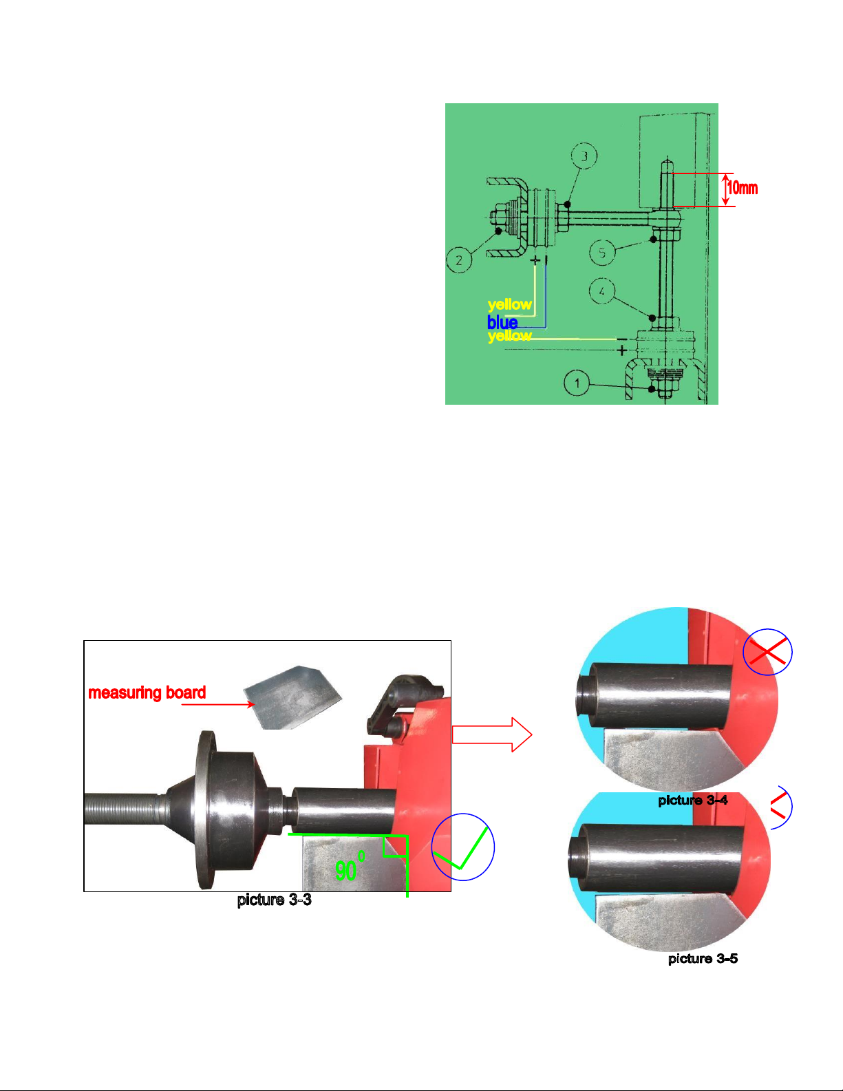
N.B. Mount the piezo units in accordance with the
position of the colored wires shown in the drawing.
4. Keeping the spindle perfectly aligned,
tighten nut 5 with a spanner, and nuts 3 and
4 by hand (by half a turn with the spanner if
necessary).
5. Refit the washers, cup springs and nuts 1
and 2. Tighten the nuts fully in order to fully
regain the elasticity of the cup springs, This will automatically ensure correct pre-loading on
the piezo (a torque wrench can be used set to 400kg·cm.).
6. For correct operation, insulation of the piezo crystals should be greater than 50 M ohm.
7. Reassemble the various parts. 8. Again carry out the automatic calibration.
Must be confirmed that the complete shaft should perpendicular to the machine body before screw
down. Please see the following showed sketch picture 3-3, 3-4 and 3-5.

Picture-3 showing that complete shaft and machine body form an angle of 90 degre, this is the
standard assembly;
Picture 3-4 showing that complete shaft and machine body form an angle less-than 90 degree,this is
incorrect assembly. Please adjust the nut ②and③.
Picture 3-5 showing that complete shaft and machine body form an angle greater than 90
degree,this is also incorrect assembly too. Please adjust the nut ②and③.

3. Scale disassembly, assembly, adjusting and
maintenance method
3.1 Diameter sensor and distance scale sensor
Please check if the following parts with red circle marked loose, check if the screw in the red
marked loose .
2, please refer to the photo P1, to check if the cores have been random.

When you install the Gauge sensor again, please screw to the Clockwise twist to the limit position,
then install, as the following photo.

Attention when installing the diameter ruler.
3.2 Width scale sensor assembly / disassembly and adjusting
method:
First step:
when
installing
the
diameter guage sensor, the
handle bar must be kept as
this station which
stick the
complete shaft tightly, as
left photo.
Disassemble
these four screws

Second step:

Fourth step

First step :

Third step:
Second step, follow as the
direction,and
following
rotate
screw
-
dirver back to 90° angle
the
as
follow
step,
First
following direction,and rotate
-
screw dirver to the end

4. Dismantle of the photoelectric sensor
Pls take off the two screws(remark with red circle part),then the user can take off the photoelectric
sensor, show as below picture Fig5-1.(Pls do not take off the blue box screws ,due to the accuracy
of the machine will be influenced).

5. Safety hood micro-switch adjustment:
If the micro-switch replaced by technician during maintenance, please adjust the machine
according to the practice situation. Once close the safety hood, please make sure the
microswitch can pushed by the cross round screw and cut off protection function.
Magneti Marelli Aftermarket Spółka z.o.o.
Plac Pod Lipami 5, 40-476 Katowice
Tel.: + 48 (032) 6036107, Faks: + 48 (032) 603-61-08
e-mail: [email protected]
www.magnetimarelli-checkstar.pl
Cross round screw can adjust
height
Adjust this length to change
the delicacy of safety hood
during open
-
close
Other manuals for MM-WB1024
1
Table of contents
Other Magneti Marelli Wheel Balancer manuals