Snap-on Incorporated EEWB314A User manual
Service Manual
SEPTEMBER 2005
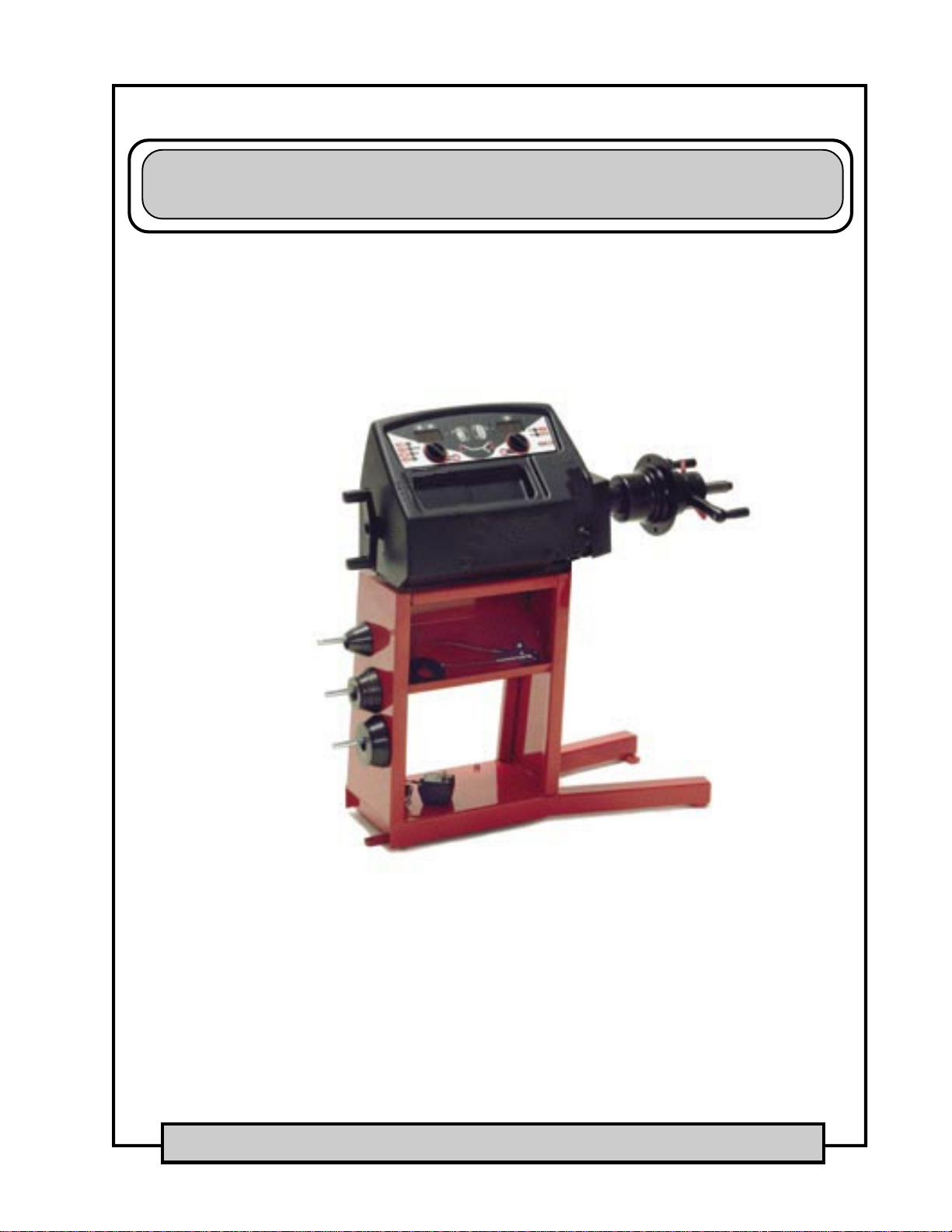
WHEEL BALANCER
EEWB314A, EEWB525A, EEWB721A

Allinformationcontainedordisclosedinthisdocument
is considered confidential and proprietary by Snap-on
Tools Company. All manufacturing, use, reproduction,
and sales rights are reserved by Snap-on Tools
Company and the information contained herein shall
not be used in whole or in part without the express
written consent of Snap-on Tools Company.

Effective
09/2005
Table Contents
INTRODUCTION
GENERAL ..........................................................................................................................................................I
FUNCTIONAL DESCRIPTION...........................................................................................................................I
BASIC BALANCER OPERATION................................................................................................................I
WEIGHT APPLICATION ..............................................................................................................................I
ALLOY MODES ...........................................................................................................................................I
ALU-S MODE ..............................................................................................................................................I
DISPLAY / CONTROL PANEL .....................................................................................................................I
GENERAL SPECIFICATIONS AND MACHINE FEATURES.............................................................................II
MAJOR FEATURES ...................................................................................................................................II
SPECIFICATIONS ......................................................................................................................................II
STANDARD EQUIPMENT ..........................................................................................................................II
ELECTRICAL SAFETY PRECAUTIONS ........................................................................................................ IV
SERVICE GUIDELINES / HANDLING STATIC SENSITIVE PCB’S................................................................ IV
CHAPTER 1 AC/DC POWER DISTRIBUTION
LOCKOUT AND/OR TAGOUT SYSTEM PROCEDURE............................................................................... 1-1
ELECTRICAL REQUIREMENTS .................................................................................................................. 1-1
AC / DC DISTRIBUTION............................................................................................................................... 1-2
DC THEORY OF OPERATION ..................................................................................................................... 1-2
PROCESSOR BOARD ........................................................................................................................... 1-2
ENCODER BOARD ................................................................................................................................ 1-2
DISTANCE POTENTIOMETER.............................................................................................................. 1-2
TRANSDUCERS .................................................................................................................................... 1-2
DISPLAY BOARD ................................................................................................................................... 1-2
KEYPAD ................................................................................................................................................. 1-2
PROCESSOR PCB....................................................................................................................................... 1-4
KEYPAD SCHEMATIC .................................................................................................................................. 1-4
TROUBLESHOOTING.................................................................................................................................. 1-5
CHAPTER 2 THEORY OF OPERATION
FUNCTIONAL DESCRIPTION...................................................................................................................... 2-1
TERMINOLOGY............................................................................................................................................ 2-2
BALANCER COMPONENTS ........................................................................................................................ 2-3
UPPER DISPLAY.................................................................................................................................... 2-3
MAIN PROCESSOR PCB ...................................................................................................................... 2-3
POWER SUPPLY PCB........................................................................................................................... 2-3
KEYPAD ................................................................................................................................................. 2-3
DISPLAY PCB......................................................................................................................................... 2-3
TEMPERATURE SENSOR..................................................................................................................... 2-3
TRANSDUCERS .................................................................................................................................... 2-3
VOLTAGE REGUALTOR ........................................................................................................................ 2-3
ENCODER.............................................................................................................................................. 2-4
ELECTRONIC BRAKE ........................................................................................................................... 2-4
SAPE (SEMI-AUTOMATIC-PARAMETER-ENTRY) ............................................................................... 2-4
VIBRATORY SYSTEM............................................................................................................................ 2-4

Effective
09/2005
CHAPTER 3 CHECKOUT, CALIBRATION AND MAINTENANCE
SHAFT IMBALANCE, WHEEL ADAPTER TO SHAFT REMOUNT TEST .................................................... 3-1
TOOLS REQUIRED WHEN SERVICING THE HANDSPIN BALANCER ..................................................... 3-2
OTHER SUPPLIES................................................................................................................................. 3-2
FUNCTIONS OF HAND SPIN BALANCER .................................................................................................. 3-3
SERVICE CODES .................................................................................................................................. 3-3
P CODE DESCRIPTIONS OF THE BALANCER .......................................................................................... 3-4
P2 RIM WIDTH INCH / MILLIMETER..................................................................................................... 3-4
P3 GRAM / OUNCE................................................................................................................................ 3-4
P4 CALIBRATION WITH ADAPTER OR DISABLE ADAPTER COMPENSATION ................................ 3-4
P7 TOGGLE MILLIMETER AND INCH FOR DIAMETER....................................................................... 3-4
P12 READ COUNTERS. ........................................................................................................................ 3-4
P14 USER CALIBRATION PROCEDURE.............................................................................................. 3-5
P18 ALU-S MODE .................................................................................................................................. 3-6
P19 ALU-S SINGLE PLANE BALANCING MODE ................................................................................. 3-6
P20 TOGGLE VEHICLE / MOTORCYCLE SOFTWARE........................................................................ 3-6
P21 KERNEL SOFTWARE..................................................................................................................... 3-6
P28 KERNEL ERROR MESSAGES ....................................................................................................... 3-6
P36 TOGGLE ANGLES OF LEFT AND RIGHT WEIGHTS. ................................................................... 3-6
P43 RESETTING THE COUNTERS ...................................................................................................... 3-6
P44 READ OR RESET PRODUCTIVITY OF USER .............................................................................. 3-6
P50 READ OUTPUT VOLTAGE OF POTENTIOMETER OF SAPE....................................................... 3-7
P53 DISPLAY TEST ............................................................................................................................... 3-7
P59 DISPLAYS THE UNBALANCE OF THE BARE SHAFT .................................................................. 3-7
P64 DISPLAYS THE TRANSDUCER OUTPUT ..................................................................................... 3-7
P74 READ SHAFT POSITION AND ANGLE .......................................................................................... 3-7
P80 SAPE GAUGE CALIBRATION ........................................................................................................ 3-7
P 83 FACTORY CALIBRATION PROCEDURE ...................................................................................... 3-8
P84 EMPTY SHAFT CALIBRATION PROCEDURE............................................................................. 3-10
P85 COPY CONTENTS OF MAIN PCB TO ENCODER, ONLY AVAILABLE IN INITIALIZATION........ 3-10
P86 COPY CONTENTS OF ENCODER TO MAIN PCB, ONLY AVAILABLE IN INITIALIZATION........ 3-10
P90 MATCH BALANCE ........................................................................................................................ 3-10
P91 OPTIMIZATION ............................................................................................................................. 3-10
P 95 CLEAN & RESET EEPROM 1 & 2 ............................................................................................... 3-10
SERVICING THE BALANCER .....................................................................................................................3-11
CONTROL PANEL REMOVAL AND REPLACEMENT ..........................................................................3-11
MAIN PROCESSOR REPLACEMENT................................................................................................. 3-12
TRANSDUCER REMOVAL................................................................................................................... 3-13
INSTALLATION OF TRANSDUCER..................................................................................................... 3-13
BRAKE SOLENOID .............................................................................................................................. 3-14
BRAKE SOLENOID ADJUSTMENT ..................................................................................................... 3-14
SHAFT BRAKE BAND.......................................................................................................................... 3-14
SAPE SYSTEM .................................................................................................................................... 3-15

Page i
Effective
09/2005
INTRODUCTION
GENERAL
The EEWB525A and EEWB721A wheel balancer is designed to compute static and dynamic imbalance of
car, light truck, motorcycle and truck wheels. For a more detailed description of each application see the
Operators Manual
FUNCTIONAL DESCRIPTION
BASIC BALANCER OPERATION
Once the balancer reaches balancing speed (120 RPM) a tone will sound, this alerts the operator to release
the handle. The balacers display will show “Spn”, calculation is done at this time. Once the weight imbal-
ance and location is known the balancer will send 12VDC to a brake solenoid braking the the shaft and
bringing the shaft to a stop. Imbalance amounts and corrective weight locations will be shown on the
display.
WEIGHTAPPLICATION
Rotate the wheel until the center green LED in the right hand row of LEDs illuminates. Apply the corrective
weight at top dead center (12 o'clock position) on the right side of the wheel. Repeat this process for the left
side of the wheel referring to the left LED’s.
ALLOY MODES
In addition to the standard Dynamic and Static modes there are 5 Alloy modes, each of which are illustrated
by LEDs on the balancer touch panel when activated. These modes are used for vehicle tire and wheels.
Alloy modes 1 through 5 are accessed by first toggling the MODE key until the balancing mode desired is
displayed. See the Operator's Manual for an explanation of Alloy Mode balancing. The last used mode will
again be used even when power is cycled.
ALU-S MODE
ALU-S mode balancing allows the operator to balance custom wheels in a true dynamic mode using con-
cealed weights while maintaining specified weight separation. See the Operator's Manual for an explanation
of ALU-S mode balancing.
DISPLAY / CONTROL PANEL
The display of the hand spin balancer shows weight amount and position for counterbalancing, plus acts as
a message center for the operator of the machine or for the technician who is repairing the machine.
The balancer may be controlled either manually or automatically. SAPE inputs for wheel distance is nor-
mally automatic and is entered when the SAPE is drawn out and the gauge finger touched to the wheel and
returned to the nested position. If the automatic features of the SAPE are nonfunctional, parameter informa-
tion may be entered manually.

INTRODUCTION
Page ii Effective
09/2005
GENERAL SPECIFICATIONS AND MACHINE FEATURES
MAJOR FEATURES
Auto Brake After Measuring Cycle
Two Window Display
Easy Electronic Access
SAPE (1d) Auto Distance Parameter Entry
Membrane Panel Data Entry
Four (4) Mounting Cones
ALU-S Function
Quick Nut With Speed Knobs
Match Balance
Total Spin Counter
Calibration Counter
Resettable Counter
Operator Productivity Counter
2 Operator Mode
SPECIFICATIONS
Shaft size: 28.5mm (1 1/16”)
Balance (shaft) speed: 90RPM
Cycle time: 15 seconds with an 'average' 14" tire & wheel combination
Balance Types: Five 2-plane alloy modes, plus static, dynamic and Match Balance modes.
Accuracy: 0.1 oz. (2.8g)
Weight Positioning resolution: 0.7 degrees
Rim Width capacity: 3"-20" (406mm)
Rim Diameter capacity: 6"-30" (152mm-660mm)
Maximum Tire Diameter: 44" (1118 mm)
Maximum Tire Width: 20" (483 mm)
Tire Weight: 120 lbs. (54.5kg)
Shipping Weight: 170 lbs. (77kg)
Power requirements: 115 / 230 VAC; 60 hz; 2 amp
STANDARD EQUIPMENT
EAA0247G21A- Rim Width Caliper
EAM0005D40A- Calibration Weight
EAA0260D63A- Standard Adapter Kit (4 cone system - 1.66" - 5.25", clamping hood, quick nut) See Part
Reference for individual part listings.

Page iii
Effective
09/2005
IMPORTANT SAFETY INSTRUCTIONS
When using this equipment, basic safety precautions should always be followed,
including the following:
1. Read all instructions.
2. Donotoperateequipmentwithadamagedpowercordoriftheequipmenthasbeen
damaged - until it has been examined by a qualified authorized service technician.
3. If an extension cord is used, a cord with a current rating equal to or more than that
of the machine should be used. Cords rated for less current than the equipment
mayoverheat. Careshouldbetakentoarrangethecordsothatitwillnotbetripped
over or pulled.
4. Always unplug equipment from electrical outlet when not in use. Never use the
cord to pull the plug from the outlet. Grasp plug and pull to disconnect.
5. To reduce the risk of fire, do not operate equipment in the vicinity of open
containers of flammable liquids (gasoline).
6. Keephair,loosefittingclothing,fingersandallpartsofthebodyawayfrommoving
parts.
7. Adequate ventilation should be provided when working on operating internal
combustion engines.
8. To reduce the risk of electric shock, do not use on wet surfaces or expose to rain.
9. Do not hammer on or hit any part of the control panel with weight pliers.
10. Do not allow unauthorized personnel to operate the equipment.
11. Use only as described in this manual. Use only manufacturer’s recommended
attachments.
12. Always securely tighten the wing nut before spinning the shaft.
13. ALWAYS WEAR SAFETY GLASSES. Everyday eyeglasses only have impact
resistant lenses, they are NOT safety glasses.
14. Balancer is for indoor use only.
SAVE THESE INSTRUCTIONS

INTRODUCTION
Page iv Effective
09/2005
ELECTRICAL SAFETY PRECAUTIONS
Make sure the balancer is unplugged before disconnecting any wires in preparation for replacing any
boards, cables or other items within the unit. Use the “Lockout and/or Tagout” procedure.
SERVICE GUIDELINES / HANDLING STATIC SENSITIVE PCB’S
Electrostatic discharge can destroy high impedance ICs if uncontrolled. Use the fol-
lowing techniques to avoid damaging ICs:
- Leave new circuit boards in their antistatic bags until ready for use.
- When replacing boards, proms, etc. be sure to turn off power to the machine first
- Use an anti-static wrist strap. Connect it to chassis ground on the equipment or to an available raw ground.
- Touch the chassis of the equipment to put yourself at the same static potential as the equipment.
- Grasp the PCB from opposite sides using your fingertips. Do not grasp the components on the board.
!
When inserting PCB’s:
- Place boards on a grounded static mat after removal.
- Remove the new PCB from the original package onto a grounded static mat. Save packaging to use
when returning defective boards.
- Remove power from the machine (un-plug from wall) before installing the PCB.
- Avoid handling components needlessly.
- Do not set PCBs on insulating surfaces such as paper, glass, rubber, or plastic.
- Static is generated by friction. The following actions promote static generation:
- Wearing silk or nylon clothing.
- Walking on carpets.
- Walking with rubber soled shoes.
Static generation is increased when certain environmental conditions exist. Conditions of low humidity
combined with wearing silks or nylons, walking on carpets, or walking with rubber soled shoes may create
large electrostatic charges on your person, capable of blowing a hole in the substrate of an IC.

Page 1-1
Effective
09/2005
CHAPTER 1
AC/DCPOWER DISTRIBUTION
LOCKOUT AND/OR TAGOUT SYSTEM PROCEDURE
1. Notify all affected employees that a lockout or tagout system is going to be utilized and why. The autho-
rized employee should know the electrical power the machine uses and it’s hazards.
2. If the machine or equipment is running, shut it down by the normal stopping procedure (depress the stop
button, open toggle switch, etc.)
3. Use appropriate devices to isolate the equipment from the power source(s). Stored energy (such as that
in springs, elevated machine members, rotating flywheels, hydraulic systems, and air gas, steam or water
pressure, etc.) must be dissipated or restrained by methods such as repositioning, blocking, bleeding
down, etc.
4. Lockout and/or tagout the energy isolating devices with individual lock(s) or tag(s).
5. After ensuring that no personnel are exposed, and as a check on having disconnected the energy
sources, operate the push button or other normal operating controls to make certain the equipment will not
operate. CAUTION: RETURN OPERATING CONTROL(S) TO “NEUTRAL” OR “OFF” POSITION
AFTER THE TEST [DE-ENERGIZED STATE].
6. The equipment is now locked out or tagged out.
ELECTRICAL REQUIREMENTS
NOTE: ANY ELECTRICAL WIRING MUST BE PERFORMED BY LICENSED PERSONNEL.
ALL SERVICE MUST BE PERFORMED BY AN AUTHORIZED SERVICE TECHNICIAN.
Check on the plate of the machine that the electrical specifications of the power source are the same as the
machine.The balancerrequires 115VAC, 50-60Hz, 1Ph,2.0Ampere. A230VACadapteris available if
required.
The balancer will also take a rechargeable portable battery pack (Versavolt). The input is able to accept a
12V, 14.4 or 18V versavolt battery pack. These are the same batteries used on the Snapon’s power tools.
NOTE: THIS MACHINE PERFORMS A SELF-TEST ROUTINE ON START-UP. THERE WILL BE ADELAY
OF SEVERAL SECONDS BEFORE THE DISPLAY IS ACTIVATED.
NOTE: ANY ELECTRICAL OUTLET INSTALLATION MUST BE VERIFIED BY A LICENSED ELECTRI-
CIAN BEFORE CONNECTING THE BALANCER.
NOTE: CHECK THAT IF ANAUTOMATIC GROUND FAULT CIRCUIT BREAKER WITH ADIFFERENTIAL
CIRCUIT IS BEING USED THAT IT BE SET AT 30 MA.

Page 1-2
CHAPTER 1 AC/DC POWER DISTRIBUTION
Effective
09/2005
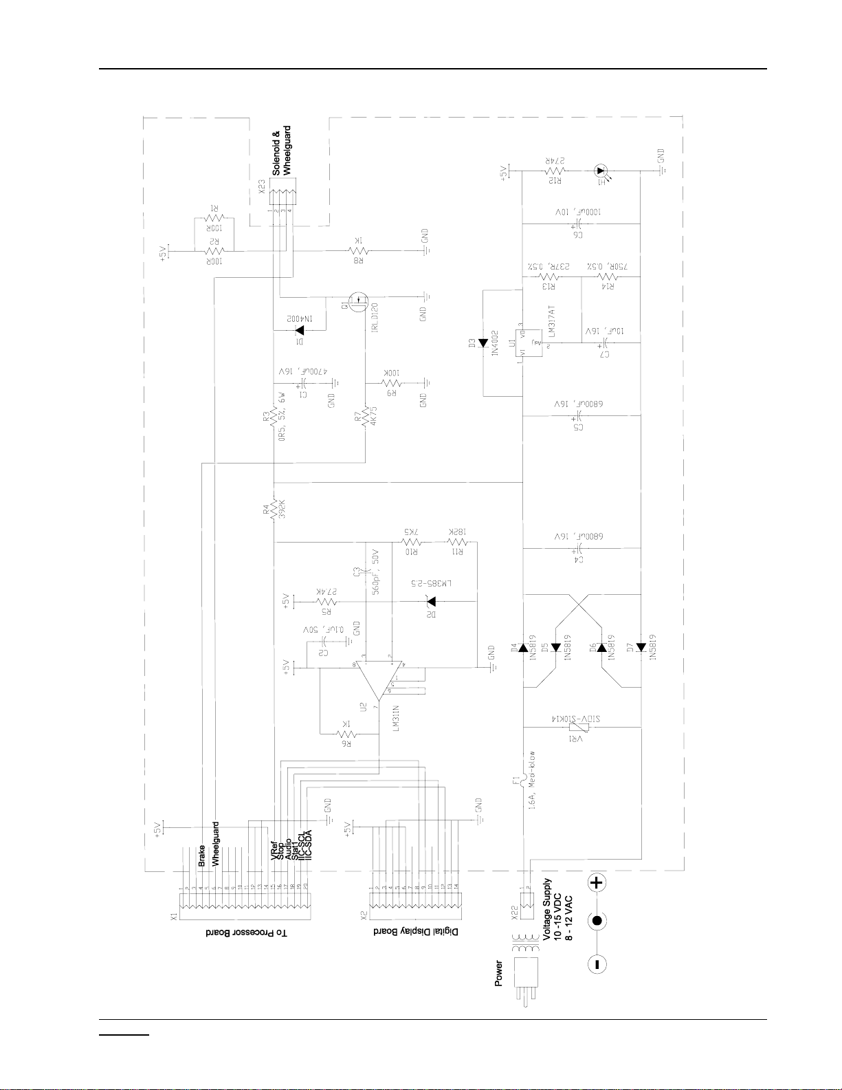
AC / DC DISTRIBUTION
The balancer is supplied with a power transformer. It is critical to have the proper input voltage in order for the
balncerto operate correctly. Thetransformer is ratedat 9VAC @1900 milliamps. 9VAC is suppliedto the Power
Supply pcb. The 9VAC passed through a bridge rectifier converting it into 12VDC. The 12VDC then is passed
through a voltage regulator coverting it into 5VDC which is used to power the processor pcb, display pcb and the
encoderpcb.
The processor pcb, display pcb and encoder all have an LED which signals that the pcb is receiving 5VDC
power.
To check power cable:
•Disconnect the power supply.
•Using a VOM, check for an output voltage at the end of the power plug 9VAC +/- 1VAC.
The electronic brake is controlled by a 12VDC solenoid. While the balancer is spinning, the main processor pcb
is gathering information from the encoder and transducers. After the needed information is gathered the main
pcb sends a signal to the power supply pcb which sends 12VDC to the brake solenoid braking the balancer and
bringing the shaft to a stop. This 12VDC can be checked at either X23 on the power supply pcb or directly at the
brake solenoid. 12VDC is only present during the brake cycle of the balancer.
DC THEORY OF OPERATION
PROCESSOR BOARD
The operating voltage for the Main Processor is 5VDC. It receives this power from the Power Supply Board
at X1 pins 32 and 34. This 5 volts also passes through the Processor Board and supplies the Encoder PCB
and the Distance SAPE.
ENCODER BOARD
The encoder receives 5VDC from the Processor Board. This voltage can be measured at the Processor
Board at X3 pin 6. The encoder is built so that there are no adjustments. The encoder disk is built onto the
shaft and cannot be replaced without replacing the vibratory member. The encoder is fitted in the vibratory
tube and consists of a reflective slotted sleeve which is mounted on the main shaft and the optoelectronic
unit.
DISTANCE POTENTIOMETER
The distance potentiometer is a 5K pot. It is supplied 5VDC from the main processor. This input voltage can
be measured at the Processor Board X6 pin 3. The output voltage is dependent upon the deflection of the
guage from the home position.
TRANSDUCERS
The transducers are installed in a manner that it forms a virtual transducer on each end of the shaft. This
configuration gives the balancer greater accuracy along with minimal amount of erroneous readings. Both
measuring transducers are arranged in one plane. The tranducers produce a DC output. The DC voltage that
is generated is sent back to the processor.
DISPLAY BOARD
The Display Board receives 5VDC from the Power Supply Board. This 5 volts can be checked at the harness
of the display board X2 pin 6 or at the Power Supply Board X2 pin 6.
KEYPAD
Thekeypad allowsoperator inputto the Main Processor Board. The output signal passes through the Power
Supply Board directly to the Main Processor.
Page 1-3
CHAPTER 1 AC/DC POWER DISTRIBUTION
Effective
09/2005
Power Supply Schematic
Page 1-4
CHAPTER 1 AC/DC POWER DISTRIBUTION
Effective
09/2005
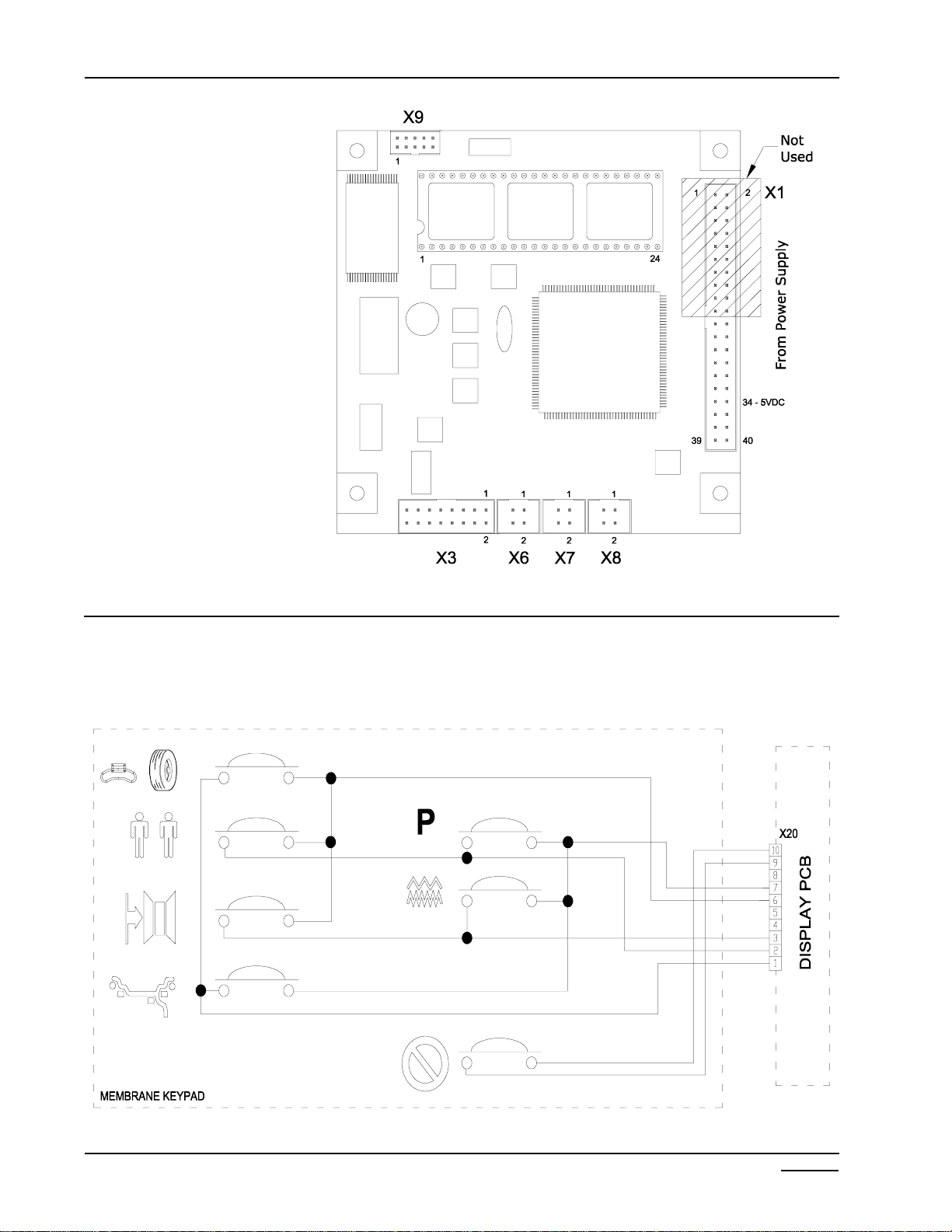
PROCESSOR PCB
X1-From Power Supply.
X3-Encoder,Tranducers &Temp
Sensor.
X6 - Distance SAPE
•Pin1=Gnd
•Pin2=Output
•Pin 3=5 VDC
X7- Not Used onHand Spin
X8- Not Used onHand Spin
X9- Not Used onHand Spin
KEYPAD SCHEMATIC

Page 1-5
CHAPTER 1 AC/DC POWER DISTRIBUTION
Effective
09/2005
TROUBLESHOOTING
COMPLAINT CORRECTIVE ACTION
I. Machine will not power up. Is the machine plugged in at the wall?
NO-> Plug machine in.
Is the balancer plugged in at the back?
NO-> Plug machine in.
Does transformer output read 9 VAC at the end of
the receptacle?
NO-> Replace power transformer.
Is 9 VAC present at pins 1 and 2 at X22 of Power Board?
NO-> Replace power wiring harness.
Is 9 VAC present at F1 on the Power Board?
(See diagram page 1-2)
NO-> Replace fuse.
Is 5 VDC present at pins 11 and 14 at X1?
NO-> Replace Power Board.
Is 5 VDC LED lit up on Processor Board?
NO-> Replace Processor Board.
Is 5 VDC present at pins 3 and 6 at X2?
NO-> Replace Power Board.
Are LED lit up on Display Board?
NO-> Replace Display Board.
II. Machine will not brake. Is 12 VDC present at pins 1 and 2 at X23 during brake cycle?
NO-> Replace Power Board.
Is 12 VDC present at the brake solenoid during brake cycle?
NO-> Replace wiring harness.
Replace brake solenoid.
Replace Processor Board.
III. Keypad will not function. Usekeypad schematic (Seediagramon page 1-3)jumper
pinsofnon working function. NO-> Replacekeypad.
Replace Display Board.
Replace Main Processor.

Page 1-6
CHAPTER 1 AC/DC POWER DISTRIBUTION
Effective
09/2005
IV. Machine chases weights. Arethe mountingaccessories in good condition?
NO-> Clean backing plate and all accessories.
Replace if necessary.
Has the balancer been calibrated?
NO-> PerformP14 and retest.
Perform P80 and P83 and retest (Pruefrotor
required).
Perform P84 and retest (Pruefrotor required).
Check vibratory system mounting bolts, are they tight?
NO-> Tighten to specification and retest.
Check P 64 does the left display change and then stabilize
when the shaft is hit?
NO-> Replace the rear transducer.
Check P 64 does the right display change and then stabilize
when the shaft is hit?
NO-> Replace the front transducer.
Is both the Front and Rear transducer tight?
NO-> Adjust to specification and retest.
Check P 36, does the left display change from 0 to 511 and
the right display change from 0.00 to 359?
NO-> Replace the Encoder Board.
Replace the Main Processor.
Replace the Vibratory System.
Does the shaft spin smoothly and freely?
NO-> Replace vibratory system.
V. Distance guage does not work. Check pins 1 and 3 at connector X6 on the Processor Board.
Is the voltage reading 5 VDC +/- 1 volt?
NO-> Replace Processor Board and retest.
Press P 50 and pull the distance guage out, does the voltage
reading on the display change?
NO-> Check to make sure string is attached to dis-
tance guage.
Replace potentiometer.
Check P 50 with the SAPE in the home position, is the
voltage reading 4.00 VDC +/- .10 volts?
NO-> Readjust voltage reading to desired setting.

Page 2-1
Effective
09/2005
CHAPTER 2
THEORY OF OPERATION
FUNCTIONAL DESCRIPTION
The EEWB314Awheel balancer is designed to compute static and dynamic imbalance of car, light truck,
motorcycle and truck wheels.
Wheels are attached to the shaft using precision centering adapters and retainers. The shaft rotates on
precision bearings on the shaft support. The rotating shaft is perfectly balanced. The wheels attached
normally represent an imbalance, which creates centrifugal force and a dynamic momentum as it is spun on
the balancer shaft. The wheel is spun by hand.
The centrifugal force and dynamic momentum created by the imbalance are detected by 2 transducers located
between the shaft support and the machine frame. These transducers contain small discs of special quartz
which generate millivolts of electric current when compressed. The current created is linearly proportional to
the compression force.
Centrifugal force and momentum vectors are generated by a rotating wheel imbalance. This causes a signal
to be generated by the transducers (which pick up only the vertical component of the constrained forces) in
the form of a periodic sine wave.
This signal is not perfectly sinusoidal, due to periodic noises from shaft bearings, support frame vibration,
gyroscopic effect, etc., which are added to the signal generated by the imbalance of the wheel. Because of
these extraneous noises, the signal produced must be filtered to compute actual imbalance.
To find wheel imbalance, knowledge of signal magnitude and timing are both required. Timing is determined
by the encoder, which consists of a electronic pcb connected to the tube of the shaft. A series of timing marks
are on the shaft which trigger light being transmitted between two optocouplers, thus generating a DC Square
wave each time a mark moves past an optocoupler. One additional mark offset from the encoders’ metallic
strip, interrupts the third optocoupler on the board, and creates a zero-signal reset or home position. The
encoder detects 512 angular positions during each turn of the shaft, plus the home or reset position. The
frequency of the DC square wave generated by the encoder allows the balancer to compute wheel speed,
wheel acceleration and weight location. The encoder and transducer signals are processed together by the
CPU to give weight amount and location readings.
The CPU board gathers the information generated from the encoder and transducer via ribbon cable. This
board is powered with 9 VAC received from the transformer.
To compute correct imbalance values, the parameters (diameter, width, and offset) of the wheel to be bal-
anced must be entered. Enter wheel parameters using the Distance Entry Arm. Slide the gauge to touch the
rim and hold. The distance to the rim will be entered automatically. Measure the rim width with the rim width
calipers (supplied) and enter the measured value. This is done by manually turning the left hand knob on the
display panel. The rim diameter is measured by turning the right hand knob on the display panel until the
desired number is shown.
Calculated imbalance values are then shown on the LED display panel after a spin cycle.
Page 2-2
CHAPTER 2 THEORY OF OPERATION
Effective
09/2005
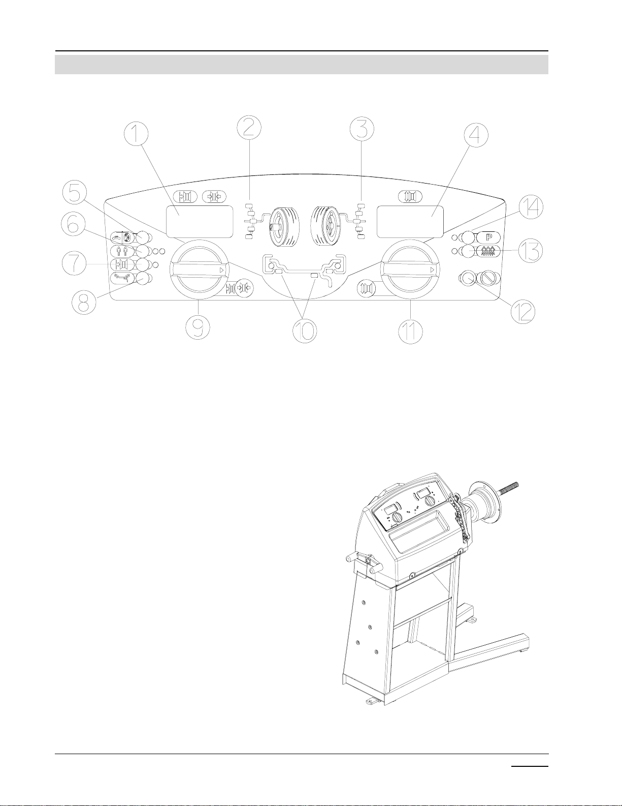
Figure 2-1 Display Layout
Figure 2-2
TERMINOLOGY
Before using the wheel balancer it is suggested that you
becomefamiliarwiththe terminology of the machine’scom-
ponents. Refer to Figures 2-1 and 2-2.
1. Display for inner plane imbalance
2. Inner plane imbalance position indicator
3. Outer plane imbalance position indicator
4. Display for outer plane imbalance
5. Display all parameters button
6. Operator A-B toggle
7. Rim offset button
8. Mode select button
9. Rim width knob & manual distance entry
10. Balance mode indicator
11. Diameter/Function knob
12. Cancel/Stop button
13. Fine-Normal button
14. Function button - “P” codes

Page 2-3
CHAPTER 2 THEORY OF OPERATION
Effective
09/2005
BALANCER COMPONENTS
UPPER DISPLAY
The upper display is made up of 4 major components. Main processor, Power Supply, Digital Display, Keypad.
Theupper display processesallinformation along withproviding all electrical requirementsto all subcompo-
nents.
MAIN PROCESSOR PCB
The microcontroller normally takes its instructions from the FLASH memory. The 40-pin IC socket is merely
used to transfer the program from an EPROM to the FLASH memory. Unlike EPROMs, FLASH memories do
not require windows for UV light in order to delete data - they can be cleared and programmed electrically.
Therefore the chips of the FLASH memories can be incorporated in economical SMD enclosures made of
plastic, which can be soldered onto the PCB. Unless otherwise stated in the program revisions, new program
versions can be installed without the need for adjustment. The main processor receives its power from the
power supply pcb and distributes the power to the encoder, transducers.
POWER SUPPLY PCB
The power supply pcb receives 9VAC from the power adapter. The power then passes through a bridge
rectifier converting it to DC power. This 12VDC is used to stop the shaft via the brake solenoid. The 12VDC
is sent to a voltage regulator that reduces the voltage to a clean steady 5VDC that is used throughout the
balancer.
KEYPAD
The keypad is used to input data into the display pcb. It connects directly to the display pcb via ribbon cable.
DISPLAY PCB
The display pcb receives power directly from the power supply pcb. It passes 5VDC to power the encoders
for both input knobs and the tone generator and the LED display. It receives the information from the main
processor pcb via the power supply pcb. This information is passed back to the processor via the power
supply.
TEMPERATURE SENSOR
The system has a new force guidance structure (patent pending). The forces at the measuring transducers
have been reduced, thus achieving good long-term stability and high measuring accuracy. The pre-
tensioning of the transducers is achieved by two leaf springs. On the vibratory system the measuring trans-
ducers are very close together so that the difference in temperature is only slight. The current vibratory
sensor has a temperature sensor. The transducers can therefore be measured by one temperature sensor
and taken into account in a fraction of a second. The temperature sensor is attached to the vibratory plate by
means of a U-shaped spring.
TRANSDUCERS
The transducers are installed such that it forms a virtual transducer on each end of the shaft. This gives the
balancer greater accuracy along with mininmal amount of erroneous readings. Both measuring transducers
are arranged in one plane. The rear transducer picks up the alternating forces of the left-hand virtual measur-
ing plane and is supported on the machine housing. The front measuring transducer is clamped between the
vibratory tube and vibratory plate, and transforms the alternating forces of the right-hand virtual plane into
electrical signals.
VOLTAGE REGUALTOR
Thebalanceris capable runningoffof Snapon’s versapackbattery packs usedto power the handtools. The
balancer incoporates an internal voltage regulator so that the balancer can accept either the 12 Volt, 14.4 Volt or
18Volt batterypacks. Thesebatteries are rechargeable using Snapon’sexternalbattery charger. The balancer
WILLNOT recharge these batteries.

Page 2-4
CHAPTER 2 THEORY OF OPERATION
Effective
09/2005
ENCODER
The encoder is built into the shaft with no adjustments. The encoder disk is built onto the shaft and cannot be
replacedwithoutreplacing the vibratory member.Thenewincrementalencoderisfitted in the vibratorytubeand
consists of a reflective slotted sleeve which is mounted on the main shaft and the optoelectronic unit. To prevent
dirtand light entering,the opening inthe vibratory tube must besealed with blackadhesive (electrical tape)
tape. Ared visible LED and four light detectors are fitted in the encoder part of the optoelectronic unit, behind
the lenses. Part of the light is reflected back from the webs of the slotted sleeve to the encoder part and fo-
cussed by the lens, such that the web-slot pattern of the sleeve is mapped on the four light detectors.Two light
detectorsareconnected to oneamplifierrespectively in theencoderpart. The difference inbrightness between
the detector pairs determines the instantaneous output states of channelsAand B. To exclude interference
from extraneous signals and to guarantee EMC-reliability, the two signals are amplified by an IC. One slot in the
sleeveis wider thanthe other 255slots. Therefore theabsolute angular positionof the mainshaft can bedeter-
mined at constant rotating speed. The surface of the slotted sleeve must be clean and shiny, the slots must
have a dull black background. Should a dirt particle have settled on a web or in a slot, it can be lifted off of the
slotted sleeve with self-adhesive tape by applying it onto a strip of strong paper so that half of the tape is on the
paperand the other halfoverhanging. CAUTION! If the slotted sleeveis twisted relativetothe main shaftwhen
beingcleaned, thestep Compensation of residual shaftunbalance has to be carried out withP84. Adefective
slotted sleeve cannot be replaced in the field because the ball bearings of the main shaft are pressed in. The
incremental encoder can be checked with test functions P36.
ELECTRONIC BRAKE
The brake solenoid is provided with 12VDC to brake the balancer. This system has been used on other
balancers with great success. While the balancer is spinning, the main processor pcb is gathering information
from the encoder and transducers. After the needed information is gathered the main pcb sends a signal to
the power supply pcb which sends 12VDC to the brake solenoid braking the balancer and bringing the shaft to
a stop.
SAPE (SEMI-AUTOMATIC-PARAMETER-ENTRY)
The handspin balancer utilizes a 1D SAPE to automatically input the distance from the balancer to the inside
weight location. The SAPE plugs into the main processor at connection X6. As the SAPE is pulled out
towards the wheel the voltage changes the correct distance is determined using the calibrated values.
VIBRATORY SYSTEM
The vibratory member is the foundation of the balancer. It houses the encoder and transducers along with a
temperture sensor for the tranducers.

Page 3-1
Effective
09/2005
CHAPTER 3
CHECKOUT,CALIBRATIONAND MAINTENANCE
SHAFT IMBALANCE, WHEEL ADAPTER TO SHAFT REMOUNT TEST
Thistestprovesthewheelbalancercenteringdevice is balanced, turns true and provesthecenteringdeviceinside
taperand balancer shaft outsidetaper (mating surfaces) aretrue.
1. Mount a medium size wheel assembly (14”), input the rim dimensions and balance the wheel assembly to
0.00 ounces imbalance in both planes. This must be balanced to exactly 0.00 in both planes.
2. Spin the balancer several times. Verify that no more than 0.05 oz. imbalance is displayed.
3. Loosen the Speed nut and rotate the tire and wheel assembly 180 degrees, making sure the cone does not
rotate. NOTE: DO NOT REMOVE THE WHEEL ASSEMBLY.
4. Operatethe balancer. Thenew imbalance displayedshould not exceed 0.25 oz.
TEST PRODUCES READINGS OUT OF TOLERANCE:
5. Removethetire and wheelassemblyfrom the balancer.
6. Checkthe tapered surfacesof the basiccentering device and balancershaft. They shouldbe clean and
smooth. Clean and retest. If the test still produces unacceptable results:
7. Using a dialindicator, measure runout ofthe balancer shafttaperedmounting surface. Acceptabletolerance
is0.0015"T.I.R. (TotalIndicated Runout). If thesurfacemeasures out oftolerance, replace thevibratory
system.
8. Perform a P80 and a P83 using the Pruefrotor and retest. These test can be found later in this Chapter.
BALANCER DIAGNOSTICS (TROUBLESHOOTING)
Many problems may be found by process of elimination. By determining the problem, then eliminating potential
problem areas starting with the most-likely to fail items, solutions to problems may be rapidly found. The Hand
Spinbalancer is composed of subsystems,each requiring severalinputsfor proper function. Withproper inputs
thesubsystem performs asexpected and producesan output. Every pieceof equipment, whenoperable,
operatesin a predeterminedmanner. Eventshave to takeplace inthe proper sequenceevery time. Abalancer
must:
Besuppliedwith correct powerandground.
Givea display output.
Accept Keypad input.
Processcommandsthrough the Computer.
Receiveandprocessencoder/transducerinputs.
Brake
Displayproperweight amount andlocation.
in that order every time, in order to balance tires. The technician should watch a machine work and make
performance assessments based on what is seen. If subsystem failure is suspected, use diagnostic tests to
confirmthe failure. Remember, everypartrequires input toproduce the expectedoutput. These outputs in turn
become inputs for further use by the system.

Page 3-2
CHAPTER 3 CHECKOUT, CALIBRATIONAND MAINTENANCE
Effective
09/2005
TROUBLESHOOT USING CORRECT DIAGNOSTICS PROCEDURES!
Balancersare relatively simplepieces of machinery. With properdiagnostic procedures, balancerproblems
should be quickly resolved. The Basics that the technician must never overlook are:
1. AC Power. The unit must be supplied with correctAC power.
2. Ground. These machines depend on properGroundingforproperand safe function. Improper or poor
ground will create problems thatare quite difficult to diagnose, andmaycreate a dangerouscondition.
Check,neverassume ground is correct!
3. DC Power. The microprocessor will not run correctly (if at all) if it is not supplied with proper DC power and
ground. Check DC power for ripple or drift ( may indicate faulty regulation or failing PCB's). Ensure there is
enoughpowerandagoodground.
4. Inputs. Check for properEncoderand Transducer signals.
5. Output- Once allvoltages and signallevels are presenta proper outputcan be expected.
TOOLS REQUIRED WHEN SERVICING THE HANDSPIN BALANCER
Tools
MetricSockets (4mm Thru15mm)
MetricWrenches(6mm Thru 15mm)
Assorted Hex Wrenches metric / standard
InchPoundTorqueWrench
FootPoundTorque Wrench
#2PhillipsScrewdriver
#2FlatHeadScrewdriver
DigitalVolt-ohm Meter
SmallScrewdriver
HiltiRotorhammer drill (InstallationOption)
Pruefrotor(H6416946)
ProgramEPROM
OTHER SUPPLIES
Loctite#242 and #272 or#609
Silicone based grease - Used for transducer
ballplacement
Puttyfor fine wheel balancing.
1, 2 and 3 ounce weights verified accurate (weigh on postal scales and trim to exact weight - paint and label)
A test tire and wheel balanced to within 0.10 oz (2.8 gr.) on both inside and outside planes or 0.20 oz. stati-
cally(mode7) is requiredduringsome troubleshooting procedures.
Inthe event of vibratorysystem replacement, theuseof a certifedPruefrotor(Figure 3-1) willbe required to
confirmconformanceto design specificationsandcertification requirements.
MountingthePruefrotor
Figure 3-1 Pruefrotor
This manual suits for next models
2
Table of contents
Other Snap-on Incorporated Wheel Balancer manuals


