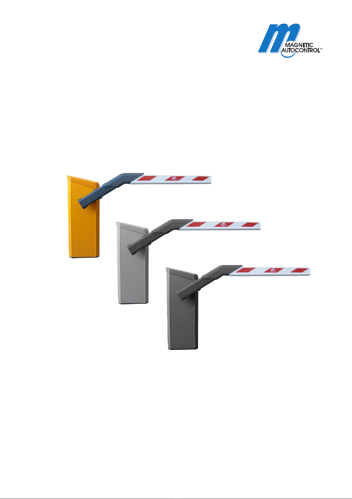
Barrier MHTMTM MicroDrive Access and Parking
Contents
5815,5001EN / Version 05 3
Contents
1General....................................................................................7
1.1 Information regarding the operating instructions ...........7
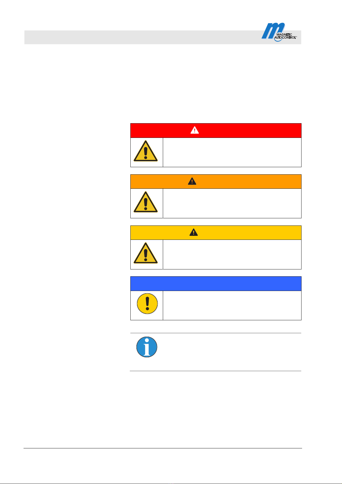
1.2 Pictogram explanation ...................................................8
1.3 Limitation of liability........................................................9
1.4 Copyright protection.......................................................9
1.5 Scope of delivery .........................................................10
1.6 Warranty ......................................................................10
1.7 Disclaimer ....................................................................10
1.8 Customer service .........................................................10
1.9 EC-Declarations of conformity .....................................11
1.10 Performance declaration..............................................11
1.11 Environmental protection .............................................11
2Safety ....................................................................................12
2.1 Intended use of the barriers.........................................12
2.1.1 Intended use for certain road vehicles .........12
2.1.2 Barrier, pedestrian traffic impossible ............12
2.1.3 Barrier, pedestrian traffic not impossible......13
2.1.4 Non-intended use .........................................13
2.2 Operator's responsibility ..............................................14
2.3 Changes and modifications .........................................14
2.4 Specialists and operating personnel............................15
2.4.1 Requirements ...............................................15
2.5 Personal protective equipment ....................................16
2.6 Occupational safety and special dangers....................16
2.6.1 Danger symbols on the
MHTMTM MicroDrive barrier..........................16
2.6.2 Hazard notes and occupational safety .........17
2.7 Danger area .................................................................23
3Identification.........................................................................24
3.1 Type plate ....................................................................24
3.2 Type code ....................................................................25
3.3 Overview: Barrier types, barrier booms,
flanges and control units..............................................26
4Technical data ......................................................................27
4.1 Access .........................................................................27
4.1.1 Dimensions and weight ................................27
4.1.2 Electrical connection ....................................28
4.1.3 Operating conditions ....................................28
4.1.4 Maximum permissible wind load classes
EN 12424......................................................29
4.1.5 Operating times ............................................29