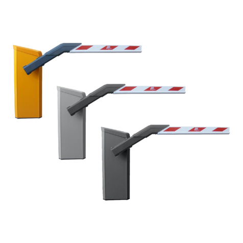
Magnetic Autocontrol MAGSTOP MIB 10-C090 User manual

Operating Instructions
581E,5005/6.00
1
Operating Instructions
MAGSTOP Traffic Barrier
MIB 10-C090
Controller Unit

Operating Instructions
2
2000 by Magnetic Autocontrol GmbH, 79650 Schopfheim, Germany

Operating Instructions
581E,5005/6.00
- 3 -
1. Safety
1.1 General safety information
This MAGSTOP gate system has been designed, built and tested using state-of-the-
art technology and left our factory only after having satisfied stringent safety and
reliability criteria. Nevertheless the gate system can represent a risk to persons and
property if it is not operated correctly. These operating instructions must therefore be
read in their entirety and all safety information contained therein must be complied
with.
The manufacturer shall refuse to accept liability and shall withdraw warranty cover if
this gate system is used incorrectly or is used for a purpose for which it was not
intended.
1.2 Intended use
The MAGSTOP MIB 10 gate may only be used at tollbooths (motorways, major roads
etc.).
The MAGTRONIC controller units have been specially designed for controlling this
Magnetic barrier.
Any other use of these barrier systems is not permitted.
Modifications or changes to the barrier or to the control modules is prohibited.
Only original Magnetic spare parts and accessories may be used.
1.3 Safety symbols used in this handbook
The following symbols are used in these operating instructions to indicate potential
risks and other safety information.
☞
Caution!
This symbol is used in this manual to designate those actions or states which
represent a potential hazard to property and equipment. Please read these
instructions very carefully.
Note!
This symbol is used in this manual to designate useful information for the
operator.
Warning!
This symbol is used in this manual to designate those actions or states which
represent a potential danger to life and limb. Please read these instructions
very carefully.

Operating Instructions
581E,5005/6.00
4
1.4 Operational safety
A safe clearance distance of at least 500 mm must be provided between the tip
of the gate arm and the closest solid obstacle (building, wall, fence etc.).
The gate operating elements must be installed at a position from which the gate
can be seen directly.
The motion of the gate arm must be directly observable by the person operating the
gate.
Whilst the gate arm is in motion nobody and no object must be in the immediate
vicinity of the gate.
If the gate and operating elements have been installed in a fixed manner, an all-pole
lockable master switch must be used.
The assembly and installation instructions must be complied with in their entirety.
Any alterations must have received prior confirmation from Magnetic. The gate arm
fixture is designed to withstand wind speeds of up to a maximum of 10 on the
Beaufort scale (= 500 N/m²). If higher wind speeds are expected, a modified gate
arm fixture must be agreed with Magnetic.
All electrical connections, wiring work and exchange of components may only be
performed by appropriately trained electrical technicians.
Before opening, the machines must be disconnected from the mains.
All technical modifications or changes to the barrier system are prohibited.
1.5 Technical developments
The manufacturer reserves the right to modify without prior notice the technical
specifications in order to accommodate the latest technical developments. Magnetic
is happy to provide information on the status of existing operating instructions and
on any alterations and extensions that may be relevant.
1.6 Warranty
Magnetic provides a warranty on its gates that covers all mechanical and electrical
components, but excludes parts subject to wear, for a period of two years from the
date of first use or for a maximum of three years from the date on which the system
was delivered provided that the operating instructions have been complied with, no
unauthorized servicing of machine components has taken place, and that no
mechanical damage to the machines is evident.

Operating Instructions
581E,5005/6.00
- 5 -
2. Assembly and installation
2.1 Constructing the foundation for the MIB gates and
the MEC-10 N/H/L control pillar
To ensure that the units are stable even when loaded, a foundation with the
following dimensions must be provided:
Depth of foundation: at least 800 mm (frost-free)
Base area of foundation: 500 x 600 mm
The base of the foundation is 100 mm larger towards the vehicle side than in the
upper section of the foundation (see Fig. S0101).
Fig. S0101
View of the foundation with
ist dimensions in mm
1.shear connector (four in total)
2.empty conduit for induction loop connections, dia. 29 mm
3.empty conduit for power supply cable, dia. 29 mm
4.empty conduit for control cables, dia. 29 mm
5.concrete foundation (BH PC 250, strength = 25 N/mm²)
Empty conduit pipes each with a diameter of 29 mm must be installed to take the
mains supply cable, the control cables and, possibly, the induction loop connections.
(barrier: 2 or 3 empty conduit pipes; control pillar: 2 empty conduit pipes).
A reinforcing steel cage is absolutely essential for the stability of the foundation (see
Fig. S0102).
Fig. S0102
Reinforcing cage for
the concrete foundation
The foundation hole is filled with BH PC 250 grade concrete (strength: 25 N/m²). The
plinth face must be carefully smoothed so that the gate housing can be positioned in
a level and horizontal manner.
Once the concrete has set to an adequate hardness, the holes for the shear
connectors can be drilled into the face of the plinth in accordance with the
dimensions shown in Fig. S0101.
500
190
155 155
500
190 155
155
600
1
2
3
4
5
800
S0101
190
S0102
5 x ∅8 440x440 St III
3 x ∅12 740x410 St III

Operating Instructions
581E,5005/6.00
6
Distance between drill holes: 190 mm (arranged in a square, see Fig. S0101)
Hole diameter: 10 mm
Depth of hole: 80 mm
Once the holes have been drilled, the four M8 x 160 shear connectors can be set in
place.
2.2 Installing the induction loops
The following section describes the standard installation of an induction loop. The
basic function of loop A is as a safety and closing loop i.e. the gate remains open for
as long as a vehicle is above the loop. The barrier closes automatically only after the
vehicle has moved away from the loopA separate loop detector i.e. the MID-detector
is required.
Non-standard installations will require prior consultation with Magnetic. The
standard installation is illustrated in Fig. S0103.
Fig. S0103
Example of how an induction
loop is installed
1.lane 2.induction loop
3.Projection of the barrier boom onto the surface of the lane assuming standard
loop installation
The following points must be considered when installing the induction loop:
• The loop must be positioned so that it is symmetrical about the vertical plane
through the gate arm. It must be recalled that the barrier boom is attached to
one side of the gate housing!
• The distance from the gate arm to the front and rear portions of the induction
loop must be at least 500 mm. If in non-standard installations (e.g. in multi-
storey car parks) significantly different distances arise, prior consultation with
Magnetic should be sought.
• The distance between the induction loop and the tip of the gate arm and the
distance between the induction loop and the barrier housing should be
approximately 300 mm.
• The loop must be installed so that it remains stationary when vehicles are passing
the barrier.
• If the lane has iron reinforcing bars then the induction loop should be positioned
at least 50 mm away from the reinforcing bars. Metals close to the induction
loop reduce its sensitivity.
300
300
1
2
3
S0103
min. 500 500

Operating Instructions
581E,5005/6.00
- 7 -
• The supply line to the loop must not be longer than 15 m. The cable must not
be coiled up within the barrier housing but should be cut to the appropriate
length instead. The supply cable must be twisted about twenty times per metre.
Once the loop has been installed, a check must be made that the resistance is < 2 Ω
and that the insulation resistance is > 1 MΩ(for inductance value - see technical
data).If the values quoted are not registered, the cable is maybe defective and
should be replaced
Procedure for installing an induction loop in bitumen or asphalt:
• The induction loops are available from Magnetic as ready-to-install cables (type:
KAS 1-KAS 5) and can be supplied in a range of lengths.
• Alternatively, a loop can be manufactured from a single wire with a 0.75 - 1.5
mm² cross-section. The inductance of the loop must lie between 70 and 500 µH,
which is usually achieved by making three to five windings.
• Using an angle grinder, a channel is cut to a depth of 30 mm into the bitumen or
asphalt surface (see Fig. S0104). The channel must have a uniform depth over its
entire length.
• The cable is laid carefully into the channel and pressed down uniformly using a
blunt object (e.g. a wooden or plastic spatula). Small wooden wedges can be
used to hold the cable in position.
Fig. S0104
Installing an induction loop in asphalt
1.gate housing 2.channel with sealing compound 3.loop cable
4.asphalt covering 5.concrete foundation
• The end of the cable must now be pushed through the empty conduit pipe
• Finally, the channel is sealed using a pourable sealing compound. When poured
into the channel, the temperature of the sealing compound must not exceed 90
°C.
• If a hot sealing compound is used (bitumen or similar), heat-resistant cables must
be selected.
Procedure for installing an induction loop under interlocking paving
stones:
;
30
300
1
2
3
4
5
S0104
Caution!
The loop cable insulation must not
be damaged during installation!
The loop cable must be completely
covered with sealing compound!

Operating Instructions
581E,5005/6.00
8
• When installing an induction cable beneath paving stones, a ready-to-install cable
(type: KAS 1-KAS 5) from Magnetic must be used.
• The induction loop cable must be laid in sand in such a way that its length is
unchanged and it suffers no damage when vehicles are passing the barrier.
• A minimum distance of 30 mm between the induction loop cable and the paving
stones is required (see Fig. S0105).
Fig. S0105:
Installing an induction loop under paving
stones
1 gate housing 2 paving stones 3 loop cable l
4 sand bed 5 crete foundation
2.3 Assembling the housing
The gate housing is positioned vertically on the upper face of the foundation and
secured using the fastenings in assembly set A that is supplied with the system. (See
Fig. S0106). In order to be able to adjust the housing later, the nuts are only lightly
tightened initially.
1 gate housing 2 nut 3 split washer
;
30
300
1
2
3
4
5
S0105
1
2
3
4
5
6
7
8
S0106
Fig,S0106
Fastening the gate housing to the
foundation

Operating Instructions
581E,5005/6.00
- 9 -
4 plain washer 5 plain washer 6 masonry anchor
7 U-section 8 concrete foundation
2.4 Installing the flange and the barrier boom
The flange is fastened to the drive shaft using two M10 x 35 hexagon socket screws
and spring washers.
The special gate arm bracket (not delivered by Magnetic) is clamped to the flange
using the fastenings fitted to the flange.
2.5 Basic mechanical settings.
1 gate arm
2 adjuster screw to set spring tension, with safety clips
3 clamping lever for flanged shaft
4 rubber buffer
5 connector piece
6 clamping lever for motor
Warning!
When tensioned, the springs and the gate arm exert considerable forces on the drive
unit and there is thus a potential risk of injury.
Any work on the BDU drive unit must therefore be carried out only when the springs
are not under tension and when the gate arm has been secured or removed!
2.6 Testing / readjustment of the springs.
The gate is set to open automatically in the event of a power failure,
the spring tension is greater than it is necessary to balance the boom.
Testing the spring settings:
Fig. S0225
Drive unit
S
0225

Operating Instructions
581E,5005/6.00
10
1. Open the gate door, swing out the mounting plate, unlock the cover and
remove.
2. Disconnect the power supply.
3. The gate arm will open automatically.
Readjusting the spring settings:
1 Remove the two safety clips from both spring adjustment screws. Tighten or
loosen the screws on the left and the right uniformly until the gate arm
move automatically to the open position, when power failure occurs.
Attention: For the test of the automatic opening function in case of power failure it
is necessary that power is on. When power failes, the controllers gives a kick to the
motor to bring the lever system out of the dead point and the arm can move
upwards.
2. Replace the screw retainers (safety clips).
2.7 Readjusting the position of the barrier boom
To readjust the position of the gate arm (for example, after excessive force has been
applied), proceed as follows:
1. Open the gate door, swing out the mounting plate, unlock the cover and
remove.
2. Raise the barrier boom by giving an opening contact.
3. Make sure that no contact for closing can be given to the controller
4. Loosen the two clamping screws on the clamping lever of the flanged shaft
just enough so that the barrier boom is held safely in position while still
allowing it to be repositioned by hand.
5. Readjust the position of the barrier boom (vertical position).
6. Retighten the clamping screws using a torque wrench (75 ftlb).
3. Power supply connection
Important! The mains voltage may only be connected to the terminals L N of the
connector unit mounted on the left side of the gate housing and the GND to the
grounding stud of the housing.
Never connect the supply lead directly to the controller unit!
4. Starting up
When the gate is set and fixed to the concrete and all connections (contacts for
OPEN and CLOSE, safety devices, power supply) are made, the gate will start
automatically with a reference cycle.
Fig. F0103.
Power supply connection
F0103

Operating Instructions
581E,5005/6.00
- 11 -
For this the gate arm will open slowely to the upper position. The motor lever will
press the end stop of this direction for some seconds. Then the motor lever will move
a few degrees back to it’s normal end position OPEN.
The first movement into the closed position will be done by a very low speed (appr.
3s to close). This is a safety device to check, if the parameters are set correctly.
All following signals will move the gate with the desired and adjusted speed.
Reset of break-away function (option)
If there is a break away contact mounted to the boom flange a reset pulse to the
push button S4 of the electronic plate (“reset after break away”) is required to
deactived the safety function which will hold open the gate arm.
This is a safety function to protect the service personal when after a break away of
the gate arm the arm is brought back to it’s normal position.
5. Controller for MIB10 gates
The controller unit has been specially designed for use with MIB 10 gates.
Most gate system configurations can be realized using the standard version of the
controller.
The position of the gate arm is continuously calculated by the controller. The
information comes from the hall-sensors inside of the motor. This replaces the limit
switch that is used in conventional barrier control systems. The combination of the
hall sensor and the controller unit guarantees the best possible control of the gate
arm movement.
Software modifications are normally included at the factory but they can also be
loaded into the controller unit at some later date. A special software tool for this
programming is necessary.
The gate is correctly wired at the factory and is supplied ready for immediate
connection.
Electrical connections that need to be made during installation are illustrated in Fig.
S0226.
Note!
If special functions are included, the connections will differ from those shown here. Please refer to the enclosed additional
wiring scheme.
S0226

Operating Instructions
581E,5005/6.00
12

Operating Instructions
581E,5005/6.00
- 13 -
5.1. Command generators: their connection and
function in the different operating modes
Important note: All command generators (e.g. push buttons, light barriers, limit
switches) must be connected as voltage-free contacts. Contact Magnetic for advice
before connecting command generators with open collector outputs.
Program 1 (Mode 3):
The gate is controlled by two switches.
Wiring of the switches see wiring diagram S1 and S2.
The switch for OPEN is prior to the DOWN switch, that means we both contacts are
closed, the gate will open.
Connections:
Potential-free contact between +24V (terminal S) and terminal 9 (S1) and terminal
10 (S2).
Additional safety devices can be connected to terminal 14 and 13. These must
function as break contacts.
Program 2 (Mode 4):
The barrier is opened and closed by two separate command generators (pulsed).
Open: contact between +24V (terminal S) and terminal 10 (S2).
Close: contact between +24V (terminal S) and terminal 9 (S1).
Additional safety devices can be connected to terminal 14 and 13. These must function as
break contacts.

Operating Instructions
581E,5005/6.00
14
6. Technical data
6.1 MAGSTOP barrier MIB 10
Maximum boom length max. 3000 mm round boom dia. 75mm
Maximum boom length max. 2500 mm octogonal boom 100x55mm
Opening/closing time 0, 6/1.2 sec adjustable via software-tool
Power consumption max. 480 W
Housing zinc-plated sheet steel
color RAL 2000
Housing dimensions 350 x 350x 1010mm
(W x D x H)
Foundation base frame stainless steel
Weight (without arm) 55 kg
Operating temp. range -20°C to +50°C
Drive brushless DC motor
6.2 Controller unit
Voltage (+/- 10%) volt 115
requency hertz 50 - 60
Max. power consumption watt 20
Fuse T10A
I/O voltage 24 V DC
RS232-communication 1 SUB-D
Mode settings 2
No. of input channels 5
No. of open collector outp. max.50mA/24V DC 5
NoofLED’s 3
Operating temp range ° C 0 - 55
Protection system IP 40
Weigth gram 2000
Dimensions mm (L - W – H) 320 x 100 x 110

Operating Instructions
581E,5005/6.00
- 15 -
7.Technical support
If operational faults arise which cannot be dealt with by your technical staff, please contact
our authorized customer service agents or specialist suppliers for assistance.
When contacting our technical support service please have available the barrier type, serial
number, version, etc. which you will find printed on the type plate on the barrier housing.
8. Spare parts and accessories
The spare parts and accessories for your barrier system are listed in our separate spare parts
and accessories catalogue which is available from Magnetic or from one of our authorized
distributors.
Table of contents
Other Magnetic Autocontrol Control System manuals
Popular Control System manuals by other brands

Helios
Helios EVS Series Installation and operating instructions

UltraLux
UltraLux SSG1Z instruction manual

micro-trak
micro-trak MT-3405 M Reference manual

Chore-Time
Chore-Time PDS Installation and operator's manual

Mitsubishi Heavy Industries
Mitsubishi Heavy Industries Smart M-Air Setup Quick Guide

FW Murphy
FW Murphy TTD Series Installation and operation manual

Nuvation Energy
Nuvation Energy NUVG5 product manual

Dungs
Dungs MPA 41 PF Series manual

Gasboy
Gasboy 8800E Series manual

Compool
Compool Cp3600 Installation & operating instructions

Nuvation Energy
Nuvation Energy NUVSSG-1250-100 product manual

Whelen Engineering Company
Whelen Engineering Company Core-C CCP9 quick start guide