manuals.online logo
Brands
  1. Home
  2. •
  3. Brands
  4. •
  5. Honeywell
  6. •
  7. Control Unit
  8. •
  9. Honeywell VCZB Series User manual

Honeywell VCZB Series User manual

SPECIFICATIONS
The specications following are nominal and conform to generally
accepted industry standards. Honeywell is not responsible for
damages resulting from misapplication or misuse of its products or
non-workmanlike installation practices.
Operating Ambient:
32 to 150°F [0 to +65°C].
5-95% RH (non-condensing)
Fluid temperatures:
34 to 203°F [1 to 95°C]
Shipping and Storage Temperature:
-40 to 150°F [-40 to +65°C]
Atmosphere:
Non-corrosive, non-explosive.
Valve Materials:
Body of bronze Cartridge of Ryton (polyphenylene sulphide)
and Noryl (polyphenylene oxide)
O-ring seals of EPDM rubber
Stem of stainless steel
Pressure Rating:
Static - 300 psig [20 Bar] maximum.
Burst - 1500 psig [100 Bar]
Operating Differential and Close-off - 60 psi maximum [4 bar]
Stem Travel:
0.4 inches [10 mm]
Flow Characteristics: Linear or equal percentage, per Table 2.
Spring Force:
1000 and 6000 Series(Silver): 14 lbf.
3000 and 7000 Series(Red): 20 lbf.
Form No. 95C-10948
VCZA,B,M,N Series
Cartridge Valve for Use with VC Series
Figure 1 - Nominal dimensions in inches [millimetres]
Table 1: VC Valve assembled dimensions
2007.05 Printed in Canada
ABB
AB
A
94 [3-3/4]
D
90 [3-9/16]
C
94 [3-3/4]
C
68 [2-3/4]
E
The VC hydronic valve consists of a valve body and replaceable
characterized cartridge assembly.
Depending on the valve model selected, they can be used with a
VC2114 or VC8114 series actuator to provide on-off ow control, or
with a VC6930 or VC7930 series actuator to provide proportional ow
control. Two way bodies may be plumbed in either direction. Three-way
bodies may be used in either diverting or mixing applications.
Replacing the cartridge rebuilds the valve. The valve body should be
able to stay in the pipes indenitely.
VC actuators, ordered separately, use cam-operated cartridge travel to
resist water hammer. Limit switches prevent motor overrun.
[1] Dimensio
n
Pipe Fitting Sizes mm Inches mm Inches mm Inches
1/2" SWEAT 89 3-1/2 130 5-1/8
1/2" NPT (int.) 98 3-7/8 136 5-11/32
3/4" NPT (int.) 130 5-1/8
3/4" SWEAT 132 5-3/16
1" NPT (int.)
1" SWEAT 5-11/32
1-1/4" SWEAT
1-1/4" NPT (int.)
[1] All models not available in all countries
111 4-3/8
142 5-5/8
113 4-7/16
136
118
EC D
110 4-5/16 4-5/8
3-11/1694
2
Table 2: VC Series Valve Bodies
MODELS:
BODIES: VCA,B,M,N ..., per table: 2
ACTUATORS (ORDER SEPARATELY)
Figure 3 - Fluid ow of 3-way
AB <-> B
AB
B
A
AB
AB <-> A
Figure 2 - Fluid ow of 2-way valves
AB
Open
A B
Closed
Accessories and Replacement Parts:
40007029-002: Cartridge installation wrench (included with all VCZZ
replacement cartridges)
272866B: Valve caps for system ushing (10 per pack)
2-way Replacement Cartridges:
VCZZ1000: quick open
VCZZ1100: high Cv, linear ow
VCZZ3100: high Cv, linear ow
VCZZ3400: medium-high Cv, equal percentage ow
VCZZ3500: low Cv, equal percentage ow
VCZZ3600: medium-low Cv, equal percentage ow
VCZZ3800: medium Cv, equal percentage ow
3-way Replacement Cartridges:
VCZZ6000: quick open
VCZZ6100: high Cv, linear ow
VCZZ7100: high Cv, linear ow
VCZZ7400: medium-high Cv, linear ow
VCZZ7500: low Cv, linear ow
VCZZ7600: medium-low Cv, linear ow
VCZZ7800: medium Cv, linear ow
Cartridge
Pi
p
e Fittin
g
Sizes
[
2
]
VCZ AA 1/2" SWEAT
VCZ BB 1/2" NPT (int.)
VCZ AL 3/4" NPT (int.)
VCZ AM 3/4" SWEAT
VCZ AR 1" NPT (int.)
VCZ AS 1" SWEAT
VCZ BE 1-1/4" SWEAT
VCZ BD 1-1/4" NPT (int.)
Quick
O
p
en
[
1
]
"1200" series cartrid
g
e has the same Cv/kV ratin
g
as "1100" series.
Suitable for use in potable water situations
[2]
[3] A port is 5% higher, and B port is 5% lower in mixing configuration. B port is 5% higher,
and A
p
ort is 5% lower in divertin
g
confi
g
uration
Models are country specific. Not all models are available in all markets.
Cv values in
g
re
y
ed-out boxes are listed for reference onl
y
:
3.3
4.7
6.6
7.0
3.3
4.7
0.6 1.3 1.9
0.7 1.5
3.2
3.5
2-way
Valve
Number Nominal Cv Ratin
g
6.6
1000 1100
[
1
]
3100 3400 3500 3600 3800
[
5
]
Equal Percentage
2-position Proportional Control [4]
3.5
6.2
7.0
7.0
2.3
4.2
3.9
Application
8.3
LinearFlow characteristic
Cartridge
Pi
p
e Fittin
g
Sizes
[
2
]
VCZ MA 1/2" SWEAT
VCZ NB 1/2" NPT (int.)
VCZ MK 3/4" NPT (int.)
VCZ ML 3/4" SWEAT
VCZ MR 1" NPT (int.)
VCZ MS 1" SWEAT
VCZ NE 1-1/4" SWEAT
VCZ ND 1-1/4" NPT (int.)
Quick
O
p
en
[4] Divide Cv value by 0.4 to obtain rangeability
[5] -800 Cartridge Cv ratings in larger bodies sizes are estimates at time of printing.
[6]
7600 7800
[5]
4.2
8.0
2.7
7100 7400
Nominal Cv Ratin
g[
3
]
3-way
Valve
Number
6000 6100 7500
2-position Proportional Control [4]Application
9.9
Flow characteristic Linear
5.2
7.4
8.3
9.0
3.8
6.6
1.3
4.2
3.8
6.6
7.4
2.2
0.8 1.5
3.4
4.2
0.7
O.S. Example: 1/2" 2-way NPT, 3.3Cv, for proportional control is VCZBB body with 3100
cartrid
g
e = VCZBB3100.
8.3
INSTALLATION
WHEN INSTALLING THIS PRODUCT:
1. Read these instructions carefully. Failure to follow them could
damage the product or cause a hazardous condition.
2. Check the ratings given in the instructions and on the product to
make sure the product is suitable for your application.
3. Installer must be a trained and experienced service
technician.
4. Always conduct a thorough check-out when installation is
completed.
5. While not necessary to remove the actuator from the body,
it can be removed for ease of installation. The actuator can
be installed in any of the four orientations to suit the most
convenient wiring direction. Actuator latching mechanism works
only when the lengths of the actuator and the valve body are
parallel to each other.
PLUMBING
The valve may be plumbed in any angle, including vertical piping,
but preferably not with the actuator below horizontal level of the
body. Make sure there is enough room around the actuator for
servicing or replacement.
3
For use in diverting applications, the valve is installed with the ow
water entering through bottom port AB, and diverting through end
ports A or B. In mixing applications the valve is installed with inlet
to A or B and outlet through AB.
Mount the valve directly in the tube or pipe. Do not grip the
actuator while making and tightening up plumbing connections.
Either hold valve body in your hand or attach adjustable spanner
(38 mm or 1-1/2") across hexagonal or at faces on the valve body
(Figure 4).
If assembling valve train on a bench, take care not to deform body
with vice. Do not place the raised "H" logo between the jaws of
the vice. Excess jaw force can deform the body.
COMPRESSION MODELS
For compression tted models, tighten the compression nuts
enough to make a watertight seal. TAKE CARE NOT TO OVER
TIGHTEN. Maximum torque limit is 33 ft-lb for the 22 mm
compression tting, and 48 ft-lb for the 28 compression tting.
SWEAT MODELS
On sweat tted valves, the cartridge is shipped loose to avoid
being damaged during the solder operation.
1. Remove valve actuator from body and solder the connecting
pipes in accordance with normal soldering practices.
2. After soldering and valve has cooled, remove cartidge assembly
from plastic bag, insert into the valve body and tighten down
with enclosed wrench until it bottoms out. DO NOT OVER
TIGHTEN (maximum torque is 40 in-lb). See Figure 5.
3. Replace valve actuator.
TO REPLACE CARTRIDGE (IF REQUIRED)
Two-way cartridges t all two-way bodies. The Cv rating of a valve
can be changed by replacing the cartridge, allowing for unique
combinations. Three-way cartridges t all three-way bodies.
Cartridges for proportional control applications have high force
springs color-coded red.
1. Disconnect power supply before servicing to avoid electrical
shock or equpiment damage.
2. Depending on the installation, it may be necessary to disconnect
leadwires to valve actuator, or depress tab on Molex™ connector
and remove. Where appropriate, label wires for rewiring.
3. Remove valve actuator by pressing up on the latch mechanism
located directly below the red manual open lever with thumb (See
Figure 5). Simultaneously press the actuator down towards the
valve body with moderate hand force and turn the actuator counter-
clockwise by 1/8 turn (45°). Lift actuator off the valve body.
!PROPER USE:
These valves are only for use in cold, warm, and hot
water applications. They are designed for a medium
temperature range of from 34 to 203°F (1 to 95 C), at a
maximum pressure of 300 psig (20 bar). They are to be
operated with the appropriate Honeywell actuators only.
Water must be properly ltered, treated and conditioned
according to local conditions.
The presence of suspended particulate(s) in the system,
such as detached calcium scale, sand, silt, large
quantities of magnetite, etc., can affect operation of
the valve. For trouble-free operation of this product,
good installation practice should include initial system
ushing, chemical water treatment, and the use of a
50 micron (or ner), 10% system side-stream lter(s).
Remove all lters before ushing.
Put the VC actuator manual lever in the fully up position or
the half open (down) position to allow initial system ushing
with the actuator mounted. This may be done without
electrical hook-up. Alternatively, reusable ush caps, part
# 272866B, may be purchased separately for use in initial
ushing of dirty hydronic systems.
Do not use boiler additives, solder ux and wetted
materials which are petroleum based or contain
mineral oil, hydrocarbons, or ethylene glycol acetate.
Compounds which can be used, with minimum 50%
water dilution, are diethylene glycol, ethylene glycol, and
propylene glycol (antifreeze solutions).
CAUTION:
Disconnect power supply before connecting wiring to prevent
electrical shock and equipment damage.
On 24V systems, never jumper the valve coil terminals, even
temporarily. This may damage the thermostat.
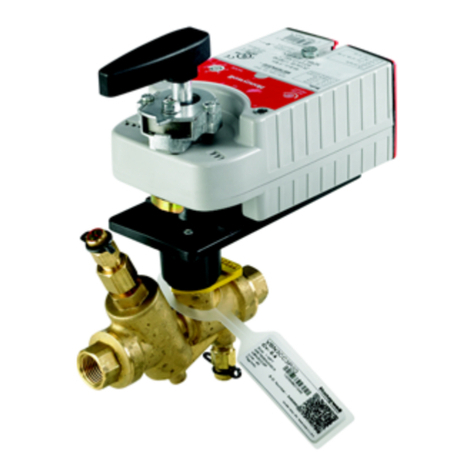
Figure 4 - Plumbing of the VC Valve
!
IMPORTANT:
The presence of iron oxide(red rust) in the system voids the
valve warranty.
4. To replace a cartridge, isolate ow to the valve using installed shut
off valves or other service equipment designed for this purpose.
Remove old cartridge with 40007029-002 wrench supplied with
the replacement unit. It may be necessary to use pliers or other
tools to remove the old cartridge due to calcium or dirt buildup in
the valve body.
5. Clean the valve surfaces marked * and ** in Figure 6 to ensure
the new cartridge O-rings seal at these points. Use care to avoid
damage to these surfaces ( ** for 3-way valves only).
6. Remove the pre-lubricated cartridge assembly from its plastic
bag. Thread it by hand into the valve body and tighten it down
with the enclosed wrench until it bottoms out. DO NOT OVER
TIGHTEN: maximum torque is 40 in-lb. [4.5 Nm]. The top
surface of the cartridge should be ush with the top edge of the
body casting.
7. Replace valve actuator by following the procedure in the "To Install
Actuator" below.
8. Reconnect leadwires or Molex™ connector if necessary.
9. Rell hydronic system or restore system ow by opening isolating
valves.
10. Restore power, and checkout operation of cartridge in valve, making
sure of no internal seat leakage or external body leakage.
Restore system pressure slowly to the valve to allow any trapped
air to escape. Check for leaks. Re-install the actuator.
TO INSTALL ACTUATOR
NOTE: Installation of a new actuator does not require draining the
system, provided the valve body and valve cartridge assembly
remain in the pipeline. Wiring may be done either before or after
the actuator is installed.
Refer to the VC Actuator Installation and Instruction sheet for
detailed wiring and check-out instructions.
1. The actuator head is automatically latched to the valve. Align
the coupling hole in the bottom of the actuator with the valve
stem. Press the actuator down towards the body with moderate
hand force and turn the actuator counter-clockwise by 1/8 turn
(45 degrees) to line up the actuator with the piping. The lock will
click when engaged (See Figure 7).
NOTE: The actuator can also be installed at right angles to the
valve body but in this position the lock mechanism will not
engage.
2. Connect leadwires.
3. Restore power and check operations.
Figure 7 - Lock Mechanism to detach Actuator
Figure 5 - Installing Cartridge Figure 6
SERVICE
This valve should be serviced by a trained, experienced service
technician.
1. If the valve is leaking, drain system OR isolate valve from the
system. Do not remove valve body from plumbing.
2. Check to see if the cartridge needs to be replaced.
3. If the motor or other internal parts of the actuator is damaged,
replace the entire actuator assembly.
NOTE: Honeywell VC series hydronic valves are designed and
tested for silent operation in properly designed and installed
systems. However, water noises may occur as a result of
excessive water velocity. Piping noises may also occur in high
temperature (over 212oF [100oC]) systems with insufcient water
pressure.
*
*
**
Automation and Control Solutions
Environmental Control Products
1985 Douglas Drive North
Golden Valley, MN 55422-3992
In Canada: Honeywell Limited-Limitee
35 Dynamic Drive, Toronto, ON M1V 4Z9

This manual suits for next models

21

Other Honeywell Control Unit manuals

Honeywell NOTIFIER LDM Series User manual

Honeywell

Honeywell NOTIFIER LDM Series User manual

Honeywell V5825B User manual

Honeywell

Honeywell V5825B User manual

Honeywell FF-SRS5988 User manual

Honeywell

Honeywell FF-SRS5988 User manual

Honeywell Elster Jeavons S200 User manual

Honeywell

Honeywell Elster Jeavons S200 User manual

Honeywell krom schroeder IFD 258 User manual

Honeywell

Honeywell krom schroeder IFD 258 User manual

Honeywell HM700AFVALVE User manual

Honeywell

Honeywell HM700AFVALVE User manual

Honeywell Esser 2 Series User manual

Honeywell

Honeywell Esser 2 Series User manual

Honeywell Notifier NZM-100-6 User manual

Honeywell

Honeywell Notifier NZM-100-6 User manual

Honeywell Centraline FALCON User manual

Honeywell

Honeywell Centraline FALCON User manual

Honeywell V4730C User manual

Honeywell

Honeywell V4730C User manual

Honeywell VCZA Series User manual

Honeywell

Honeywell VCZA Series User manual

Honeywell TC Series Manual

Honeywell

Honeywell TC Series Manual

Honeywell A4021 Series User manual

Honeywell

Honeywell A4021 Series User manual

Honeywell T7560A User manual

Honeywell

Honeywell T7560A User manual

Honeywell Braukmann BV300 User manual

Honeywell

Honeywell Braukmann BV300 User manual

Honeywell SV2 Series User manual

Honeywell

Honeywell SV2 Series User manual

Honeywell LC13-510 User manual

Honeywell

Honeywell LC13-510 User manual

Honeywell TM300 User manual

Honeywell

Honeywell TM300 User manual

Honeywell S4560 User manual

Honeywell

Honeywell S4560 User manual

Honeywell Notifier FCM-1 User manual

Honeywell

Honeywell Notifier FCM-1 User manual

Honeywell BA295STN-11/2C User manual

Honeywell

Honeywell BA295STN-11/2C User manual

Honeywell THP9045 User manual

Honeywell

Honeywell THP9045 User manual

Honeywell 5496 Operating instructions

Honeywell

Honeywell 5496 Operating instructions

Honeywell BA295I User manual

Honeywell

Honeywell BA295I User manual

Popular Control Unit manuals by other brands

inveo USCADA user manual

inveo

inveo USCADA user manual

HEROSE 7111 operating instructions

HEROSE

HEROSE 7111 operating instructions

ETAS ES4350.1 user guide

ETAS

ETAS ES4350.1 user guide

Diamond Systems Pyxis-MM user manual

Diamond Systems

Diamond Systems Pyxis-MM user manual

oventrop Multidis SFQ operating instructions

oventrop

oventrop Multidis SFQ operating instructions

INVT IVDM-20 user manual

INVT

INVT IVDM-20 user manual

ASCOM NUMI2-HE Installation sheet

ASCOM

ASCOM NUMI2-HE Installation sheet

Vag 220-DS Operation and maintenance manual

Vag

Vag 220-DS Operation and maintenance manual

Emerson Liebert OpenComms SL-19534 user manual

Emerson

Emerson Liebert OpenComms SL-19534 user manual

Orbinox EB Installation, operation & maintenance manual

Orbinox

Orbinox EB Installation, operation & maintenance manual

Victaulic 751 FireLock Series Installation, Maintenance, and Testing Manual

Victaulic

Victaulic 751 FireLock Series Installation, Maintenance, and Testing Manual

SMC Networks IBV1 Series Operation manual

SMC Networks

SMC Networks IBV1 Series Operation manual

Quectel UG89 Hardware design

Quectel

Quectel UG89 Hardware design

M-system M6DXF1 manual

M-system

M-system M6DXF1 manual

SmartOne 70-600000-001 installation instructions

SmartOne

SmartOne 70-600000-001 installation instructions

PRASTEL MT15000/2 Technical instructions

PRASTEL

PRASTEL MT15000/2 Technical instructions

Crane D1088 Installation, operation and maintenance instructions

Crane

Crane D1088 Installation, operation and maintenance instructions

Huawei PDU5000 quick guide

Huawei

Huawei PDU5000 quick guide

manuals.online logo
manuals.online logoBrands
  • About & Mission
  • Contact us
  • Privacy Policy
  • Terms and Conditions

Copyright 2025 Manuals.Online. All Rights Reserved.