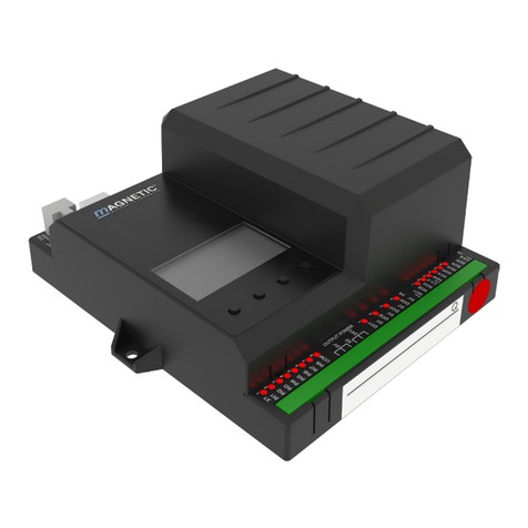
Magnetic MPT-333 User manual

Description
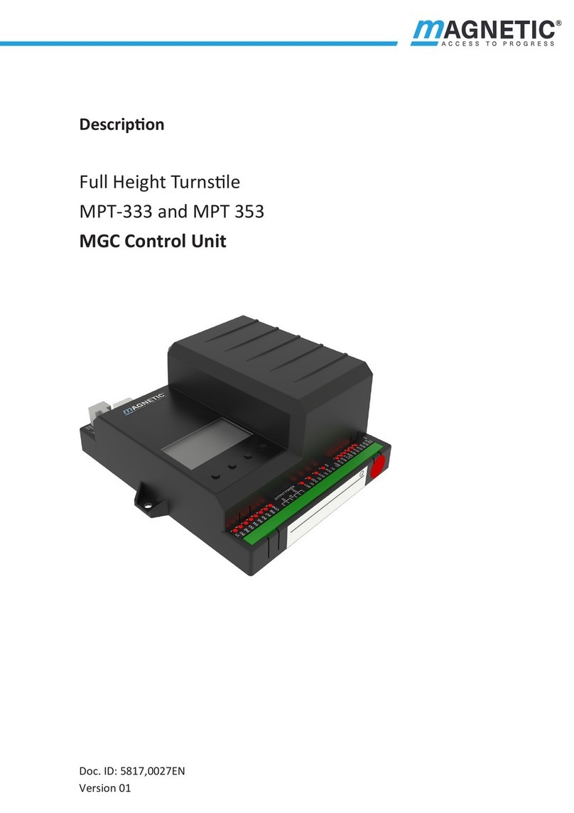
Full Height Turnstile MPT-333
MGC control unit
Doc.ID: 5817,0027EN
Version 00

2
MGC control unit
MAGNETIC AUTOCONTROL GMBH
Grienmatt 20
D-79650 Schopfheim
Germany
Phone +49 7622 695 5
Fax +49 7622 695 802
www.magnetic-access.com

3
MGC control unit
Contents
Contents
1 Notes on the document 5
1.1 Purpose and contents of this description 5
1.2 Symbols and illustrations used in this document 6
1.2.1 Warning notes and notes 6
1.3 Target group 7
1.3.1 Personnel – activities and qualifications 7
2 Digital inputs, digital outputs and relay outputs 8
2.1 Digital inputs 8
2.2 Digital outputs and relay outputs 10
2.3 Digital power outputs of the MFM01 plug-in modules 12
3 Parameterising control unit 13
3.1 Changing menu language 13
3.2 Entering password 17
3.3 Control unit elements 18
3.4 Displays of the control unit 19
3.5 Symbols in the display 20
3.5.1 Control button functions 20
3.5.2 Further symbols 21
3.6 Setting display contrast 22
3.7 Protecting parameterisation from access 22
3.8 Parameterise value 22
3.9 Switching the "Service" mode on and off 24
4 Description of menus and parameters 25
4.1 Menu "Information" 25
4.2 Menu "Setup" 26
4.2.1 Hold-open time 26
4.2.2 Permanent open 26
4.2.3 Interlock 27
4.2.4 Vend count 27
4.2.5 Signalling 28
4.2.6 Random function 29

4
MGC control unit
Contents
4.3 Menu "In-/Outputs" 31
4.3.1 Inputs 31
4.3.2 Outputs 31
4.4 Menu "Service" 32
4.4.1 Gate HW 32
4.4.2 Further parameters 35
4.5 Menu "System" 35
4.6 Menu "Passage counter" 36
4.7 Menu "Information" 36
4.8 Menu "Factory settings" 37
5 Function description 40
5.1 Versions and definitions 40
5.2 Function sequence 42
5.3 Start-up and regular movement sequence 43
5.4 Operation modes 43
5.4.1 Pulse operation in both directions
without vend count 43
5.4.2 Pulse operation in both directions with vend count 44
5.4.3 Permanent open in both directions 44
5.4.4 Pulse operation in one direction, permanent open in
the other direction 44
5.5 Emergency 45
5.6 Random function 45
6 Corrective action 46
6.1 Safety in troubleshooting 46
6.2 Malfunctions turnstile 47
6.3 Event, warning and error messages in the display 47
6.3.1 Event, warning and error messages – logic control
(control unit) 48
6.3.2 Event, warning and error messages – all modules 49
6.4 Perform reset 50
7 Menu setup 51
Index 55

5
MGC control unit
Notes on the document
1 Notes on the document
1.1 Purpose and contents of this description
This document describes the MGC control unit from the program versions
listed below.
Software number (software #) and software version (SW version) are displayed
in the menu "Module info".
Designation Software # SW version
Gate Controller 4915.1006 1.1
Table 1: Programme versions MGC control unit
IMPORTANT!
For information on design and function, for technical data,
installation and assembly, electrical connection, commissioning
and cleaning and maintenance, see the separate operating
instructions "Full height turnstile MPT-333 (Doc.ID: 5817,0028)".

6
MGC control unit
Notes on the document
1.2 Symbols and illustrations used in this document
1.2.1 Warning notes and notes
Warning notes are characterised by pictograms in these operating instructions.
A warning note starts with a signal word that expresses the extent of the
hazard.
It is absolutely essential to observe the warning notes and to proceed with
caution in order to prevent accidents as well as bodily injuries and property
damage.
Warning Notes
DANGER
The signal word DANGER points to an immediately dangerous
situation, which leads to death or severe injuries if it is not
avoided.
WARNING
The signal word WARNING points to a potentially dangerous
situation, which can lead to death or severe injuries if it is not
avoided.
CAUTION
The signal word CAUTION points to a potentially dangerous
situation, which can lead to minor injuries if it is not avoided.
NOTICE
The signal word NOTICE points to a potentially harmful situation,
which leads to property damage if it is not avoided.

7
MGC control unit
Notes on the document
Notes and recommendations
IMPORTANT!
The signal word IMPORTANT highlights useful notes and
recommendations as well as information for an efficient and
trouble-free operation.
1.3 Target group
1.3.1 Personnel – activities and qualifications
All work on the control unit may only be carried out by technicians and
electricians with the following qualifications.
Designation Qualification
Technician › Has completed training as a plant mechanic, plant fitter,
assembly mechanic, assembly fitter or has a comparable
technical education.
› Has completed training as an electrical safety expert.
› Has additional knowledge and experience.
› Knows the associated technical terms and regulations.
› Can assess the work assigned to her/him, recognises
possible dangers and take suitable safety measures.
Electrical specialist › Has technical training which entitles him to carry out
and monitor electrical work for commercial purposes.
› Has additional knowledge and experience.
› Knows the associated technical terms and regulations.
› Can assess the work assigned to her/him, recognises
possible dangers and take suitable safety measures.
Table 2: Qualification of the personnel – MGC control unit

8
MGC control unit
Digital inputs, digital outputs and relay outputs
2 Digital inputs, digital outputs and relay outputs
WARNING
Improper wiring and parameterisation of the control unit!
Improper wiring and parameterisation of the control unit can
lead to undesired functions and thus to injuries.
› Only qualified electricians or technician with additional
"electrical safety expert" training may wire and parameterise
the control unit.
› The electrical connection of the signal transmitters to the IN1
to IN8 inputs must fit the parameterisation.
äFor parameterisation see Page 13, chapter 3.
2.1 Digital inputs
äFor the definition "Entry" and "Exit" see Page 40, chapter 5.1.
By parameterising the inputs, you assign certain functions to the inputs. For
example, if you parameterise the "Over-climb detection" function for input
IN7, you must connect a sensor for the over-climb detection to this input.
If the function is marked with "|", the input is inverted (Fail Safe).
The following functions are assigned to the inputs as default settings.
Clamp Description Function
IN1 Digital Input 1 | Emergency open
IN2 Digital Input 2 Open entry
IN3 Digital Input 3 Open exit
IN4 Digital Input 4 Random function
IN5 Digital Input 5 Confirm warnings
IN6 Digital Input 6 Inhibit opening
IN7 Digital Input 7 Sensor B1
IN8 Digital Input 8 Sensor B2
Table 3: Factory settings "Digital inputs"

9
MGC control unit
Digital inputs, digital outputs and relay outputs
Clamp Function
– Inputs that you assign this function "–" to are being deactivated.
| Emergency open Emergency situation (Fail Safe)
Connect fire service switches, emergency opening contacts, etc. to this
input. This input has the highest priority. As soon as +24 V DC are applied to
this input, the pedestrian gate is in operation.
If there is no signal at this entry, the passage is cleared in both directions.
This input function is high priority to all other input functions.
Confirm warnings Confirm warnings
A pulse at this input confirms the "Warning" output function. The output is
reactivated the next time a warning occurs.
The number of the warning message remains stored in the event list until
the control unit is restarted.
Open entry Opening pulse for the passage from the zone not controlled (ZNC) to the
zone controlled (ZC)
If the signal is present for longer than 3 seconds, Permanent open is
activated. äPage 26, chapter 4.2.2, Parameter "Permanent open".
Open exit Opening pulse for the passage from the zone controlled (ZC) to the zone not
controlled (ZNC)
If the signal is present for longer than 3 seconds, Permanent open is
activated. äPage 26, chapter 4.2.2, Parameter "Permanent open".
Inhibit opening Lock pedestrian gate
Use this input to lock the pedestrian gate in both passage directions. No
opening signals are accepted anymore. Input IN1 "| Emergency open"
remains superordinated. This means that the pedestrian gate can also be
opened via input IN1 when the pedestrian gate is locked.
Random function Activate random function, confirm hits
As soon as +24 V DC are applied to this input, the random function is
activated. If a hit is generated, the hit can be confirmed with a 0 V pulse via
this input.
For this entry to be effective, you must select the option "Counting" or
"Random" for the parameter "Mode" in the "Random function" menu.
äPage 29, chapter 4.2.6, "Random function" menu.
Sensor B1 (internal
use)
Connection proximity sensor B1
Sensor B1 is connected to this entry by default. The inductive proximity
sensor is used to detect the end positions.
Sensor B2 (internal
use)
Connection proximity sensor B2
Sensor B2 is connected to this entry by default. The inductive proximity
sensor is used to detect the end positions.
Table 4: Function digital inputs

10
MGC control unit
Digital inputs, digital outputs and relay outputs
2.2 Digital outputs and relay outputs
äFor the definition "Entry" and "Exit" see Page 40, chapter 5.1.
By parameterising the outputs, you assign certain functions to the outputs.
If the function is marked with "|", the output is inverted (Fail Safe).
The following functions are assigned to the outputs as default settings.
Clamp Description Function
DO1 Digital output 1 GED red entry
DO2 Digital output 2 GED green entry
DO3 Digital output 3 GED red exit
DO4 Digital output 4 GED green exit
NO1 Relay output 1 Passage pulse entry
NO2 Relay output 2 Passage pulse exit
NO3 Relay output 3 –
NO4/NC4 Relay output 4 Passage free entry
NO5/NC6 Relay output 5 Passage free exit
NO6/NC6 Relay output 6 Random hit
Table 5: Factory settings Digital outputs and Relay outputs
Function Function
– Outputs that you assign this function "–" to are deactivated.
| Error When the control unit recognises any safety-relevant error or error, the
output with this function is deactivated (Fail safe). äPage 47, chapter 6.3.
| Warning When the control unit recognises any Warning, the output with this function
is deactivated (Fail safe). äPage 47, chapter 6.3.
Gate ready Pedestrian gate is ready for operation
This output is activated as soon and as long as the pedestrian gate is ready
for operation.
Passage pulse entry Counting pulse for the passage from the zone not controlled (ZNC) to the
zone controlled (ZC)
When the next end position is reached in the zone controlled direction, a
counting pulse (300 ms) is emitted via this output. A counting pulse is also
emitted in the "Permanent open" operating mode.
Passage pulse exit Counting pulse for the passage from the zone controlled (ZC) to the zone not
controlled (ZNC)
When the next end position is reached in the zone not controlled direction, a
counting pulse (300 ms) is emitted via this output. A counting pulse is also
emitted in the "Permanent open" operating mode.

11
MGC control unit
Digital inputs, digital outputs and relay outputs
Function Function
Passage free entry Control of display "Passage in zone controlled direction cleared"
When the passage in the zone controlled direction is cleared, a permanent
signal is emitted via this exit. This exit may also be used to block a pulse
encoder such as a card reader for the opposite direction. The request
generator must be equipped with a lock input for this.
Passage free exit Control of display "Passage in zone not controlled direction cleared"
When the passage in the zone not controlled direction is cleared, a
permanent signal is emitted via this output. This exit may also be used to
block a pulse encoder such as a card reader for the opposite direction. The
request generator must be equipped with a lock input for this.
Buzzer/Siren (alarm) Acoustic signal transmitter
This output is used to connect a signal transmitter.
Random hit Hits of the random function, signal transmitter
The random function generated a hit. You can connect a signal lamp or a
siren to this output, for example.
The passage remains blocked until the random hit / validation is confirmed
with a 0 V pulse at the "random function" input.
Service mode active Pedestrian gate in service mode
As soon as the service mode is switched on via the slider on the control unit
MGC, this output is activated.
GED red entry Gate End Display connection
Connect the GED "red" of the zone not controlled to this output.
GED green entry Gate End Display connection
Connect the GED "green" of the zone not controlled to this output.
GED red exit Gate End Display connection
Connect the GED "red" of the zone controlled to this output.
GED green exit Gate End Display connection
Connect the GED "green" of the zone controlled to this output.
Magnet RL1 (internal
use)
Connection magnet RL1
Magnet RL1 for locking is connected to this exit by default. The magnet locks
in passage direction left.
Magnet RL2 (internal
use)
Connection magnet RL2
Magnet RL2 for locking is connected to this exit by default. The magnet locks
in passage direction right.
Table 6: Function digital outputs and relay outputs

12
MGC control unit
Digital inputs, digital outputs and relay outputs
2.3 Digital power outputs of the MFM01 plug-in modules
The control unit is equipped with the plug-in module MFM01 with the function
"Magnets for locking".
Furthermore, the control unit can be equipped with additional plug-in modules
MFM01.
Power outputs 60 V / 3 A are available via the optional MFM01 plug-in
modules. The function is permanently assigned via the slot number.
Mag00838
21
3
4
5
Fig. 1: Slot numbers
Slot number Terminal plug-
in module
LED plug-in
module
Function
1 Magnets for locking
1Red Magnet RL1
2 Green Magnet RL2
3 Yellow –
2 On-site signalling, e.g. lights for zone controlled (ZC)
1 Green Free in zone not controlled
direction
2Red Locked in zone not controlled
direction
3 Yellow –
3 On-site signalling, e.g. lights for zone not controlled (ZNC)
1 Green Free in zone controlled direction
2Red Locked in zone controlled direction
3 Yellow –
4 –
5 –
Table 7: Functions for MFM01 plug-in modules

13
MGC control unit
Parameterising control unit
3 Parameterising control unit
3.1 Changing menu language
The default setting in the MGC control unit is the menu language "English".
Change the menu language as follows:
The operational view is displayed.
Mag00859
10
FlowMotion MPT333
1
0
– –
– –
Fig. 2: Example "Operational View”
1. Press right operating button « ».
2. Access to parameterisation can be password-protected. If password
protection was activated, you are asked to enter a password.
Mag00818
–––
0
Password
Fig. 3: View "Enter password"

14
MGC control unit
Parameterising control unit
3. The "Main menu" menu is displayed. The "Setup" menu has a dark
background and is thus selected.
Mag00819
Setup
In-/Outputs
Service
System
Main menu
Fig. 4: View "Main menu – Setup"
4. Select the menu "System" with the two middle buttons « », « ».
Mag00820
Setup
In-/Outputs
Service
System
Main menu
Fig. 5: View "Main menu – System"
5. Confirm selection with the right control button « ». The following view
is displayed. The menu "Language" is chosen.
Mag00821
Language
Date/Time
System
Fig. 6: View "Language"

15
MGC control unit
Parameterising control unit
6. Confirm selection with the right button « ». The following view is
displayed. The menu language "English" is chosen.
Spanish
French
Mag00822
English
Language
Fig. 7: View "Language - English"
7. Select the language "German" with the two middle buttons « », « ».
The language "German" has a dark background.
French
Mag00823
German
English
Language
Fig. 8: View "Language - German"
8. Use the right button « » to select the new menu language. Your
selection is marked with the symbol « ».
French
Mag00824
German
English
Language
Fig. 9: View "Language” - German, step 2"

16
MGC control unit
Parameterising control unit
9. Use the left button « » to leave the "Language" menu. The safety
prompt "Save changes? " appears.
Mag00825
Save changes?
Language ?
Fig. 10: View "Safety prompt – Save changes?"
Push the left button « » if you do not want to save the changes. The menu
language "English" remains active.
10. Confirm safety prompt with the right button « ». The new menu
language "German" is activated. The following view is displayed:
Mag00821
Sprache
Datum/Zeit
System
Fig. 11: View "Menu system – Menu language "German" is activated
11. Press the left button « » repeatedly until the operating view is displayed
again. äPage 13, Fig. 2.

17
MGC control unit
Parameterising control unit
3.2 Entering password
You need to enter a password in the following cases:
› You would like to change parameters in the control unit and the password
protection was activated.
› You would like to reset the parameters to factory settings.
If a password is required, the following view is displayed:
Mag00818
–––
0
Passwort
Fig. 12: View "Password"
1. Use the two middle buttons « », « » to enter the first digit of the
password.
2. Use the right button « » to select the second digit of the password. The
following view is displayed:
Mag00828
––
*0
Passwort
Fig. 13: View "Enter second digit of the password"
3. Use the two middle buttons « », « » to enter the second digit of the
password.
4. Use the right button « » to select the third digit of the password.
5. Use the two middle buttons « », « » to enter the third digit of the
password.

18
MGC control unit
Parameterising control unit
6. Use the right button « » to select the fourth digit of the password. The
following view is displayed:
Mag00829
*0
**
Passwort
Fig. 14: View "Enter fourth digit of the password"
7. Use the two middle buttons « », « » to enter the fourth digit of the
password.
8. Confirm the password with the right control button « ».
3.3 Control unit elements
Mag00827
1
3
2
Setup
In-/Outputs
Service
System
Main menu
Fig. 15: Control unit elements MGC
1 Menu
2 Current function of the 4 control buttons
3 Control buttons

19
MGC control unit
Parameterising control unit
3.4 Displays of the control unit
Mag00860
10
FlowMotion MPT333
1
0
– –
– –
6
3
4
1
2
57
9
8
10
Fig. 16: Example "Operational View"
1 Type pedestrian gate here MPT-333 electromotive
2 Status display, here ready for operation
3 Angle of rotation, here 0
4 Current function of the right control button, here calling menu "Main menu"
5 Validations exit, here locked
6 Hold-open time exit, here locked
7 Operating display, here passage direction left enabled
8 Current function of the left control button, here calling menu "Information"
9 Holding-open time entry, here 10
10 Validations entry, here 1
Mag00830
5
3
4
60
3
15 sek
1 2
Hold-open time
Fig. 17: Example "Screen Change Value"
1 Parameter
2 Current value
3 Possible upper value
4 Possible lower value
5 Current functions of the control buttons

20
MGC control unit
Parameterising control unit
3.5 Symbols in the display
3.5.1 Control button functions
The control unit is equipped with 4 control buttons. The function of the control
buttons change depending on the current view in the display. The current
functions are shown in the display.
Clamp Description
› Call menu "Information".
› Scroll menu "Information".
Call menu "Main menu". Make all settings in the menu "Main
menu".
Leave current menu level. The next-higher menu level is displayed.
› Call next-lower menu level.
› Select desired option or desired value. When the desired option
was selected, the symbol is displayed.
Option was selected but not yet stored
› Within one menu level: Move cursor (market) upwards.
› For setting value: Increase figure.
› Within one menu level: Move cursor (market) downwards.
› For setting value: Decrease figure.
Move cursor one position to the right.
› Delete error message.
› When changing settings: Cancel changing process.
Table 8: Control button functions
Other manuals for MPT-333
1
Table of contents
Other Magnetic Control Unit manuals
Popular Control Unit manuals by other brands

Adeunis RF
Adeunis RF SIGFOX user guide

DMP Electronics
DMP Electronics 734 Installation and programming guide

PVA
PVA MV600 Series owner's manual

Allen-Bradley
Allen-Bradley POINT I/O 1734-OB2 installation instructions

Jaycar
Jaycar Maycar Electronic Dice Kit quick guide

Keysight Technologies
Keysight Technologies 34946A user guide

Move
Move MAMWLE Series manual

Sharp
Sharp LS013B7DH01 Technical Literature

Z3 Technology
Z3 Technology Z3-DM816X-RPS RDK user guide

Harvia
Harvia XENIO COMBI CX30C-U1 Instructions for installation and use

Bodine
Bodine 3984 Instructions for installation and operation

Burkert
Burkert 0301 operating instructions