2 ORI-46.650 Jupiter Magnetostrictive Transmitters ORI-46.650 Jupiter Magnetostrictive Transmitters 3
Read this Manual Before Installing
is manual provides information on the Jupiter®
magnetostrictive transmitter. It is important that all
instructions are read carefully and followed in sequence.
Detailed instructions are included in the Installation section
of this manual.
Conventions Used in this Manual
Certain conventions are used in this manual to convey
specic types of information. General technical material,
support data, and safety information are presented in
narrative form. e following styles are used for notes,
cautions, and warnings.
Notes
Notes contain information that augments or claries an
operating step. Notes do not normally contain actions.
ey follow the procedural steps to which they refer.
Cautions
Cautions alert the technician to special conditions that
could injure personnel, damage equipment, or reduce a
component’s mechanical integrity. Cautions are also used
to alert the technician to unsafe practices or the need for
special protective equipment or specic materials. In this
manual, a caution box indicates a potentially hazardous
situation which, if not avoided, may result in minor or
moderate injury.
Warnings
Warnings identify potentially dangerous situations or
serious hazards. In this manual, a warning indicates an
imminently hazardous situation which, if not avoided,
could result in serious injury or death.
Safety Messages
Follow all standard industry procedures for servicing
electrical equipment when working with or around high
voltage. Always shut o the power supply before touching
any components.
WARNING! Explosion hazard. Do not connect or
disconnect designs rated Explosion proof
or Non-incendive unless power has been
switched off and/or the area is known to be
non-hazardous.
Low Voltage Directive
For use in Installation Category II, Pollution Degree 2. If
equipment is used in a manner not specied by the man-
ufacturer, protection provided by the equipment may be
impaired.
Notice of Trademark, Copyright, and Limitations
Orion & Orion logotype, Magnetrol & Magnetrol
logotype, and Jupiter are registered trademarks of Magnetrol
International.
Copyright © 2016 Magnetrol International.
All rights reserved.
Performance specications are eective with date of issue
and are subject to change without notice. Magnetrol reserves
the right to make changes to the product described in this
manual at any time without notice. Magnetrol makes no
warranty with respect to the accuracy of the information in
this manual.
Warranty
All Magnetrol/Orion electronic level and ow controls are
warranted free of defects in materials or workmanship for
one full year from the date of original factory shipment.
If returned within the warranty period; and, upon factory
inspection of the control, the cause of the claim is determined
to be covered under the warranty; then, Magnetrol/Orion
will repair or replace the control at no cost to the purchaser
(or owner) other than transportation.
Magnetrol/Orion shall not be liable for misapplication, labor
claims, direct or consequential damage or expense arising
from the installation or use of equipment. ere are no
other warranties expressed or implied, except special written
warranties covering some Magnetrol/Orion products.
Quality Assurance
e quality assurance system in place at Magnetrol guar-
antees the highest level of quality throughout the com-
pany. Magnetrol is committed to providing full customer
satisfaction both in quality products and quality service.
Magnetrol’s quality assurance system is registered to ISO
9001 arming its commitment to known international
quality standards providing the strongest assurance of
product/service quality available.
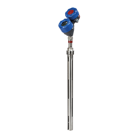
Jupiter JM4 Magnetostrictive Transmitter
1.0 Installation
1.1 Installation Prep ............................ 4
1.1.1 Factory Mounting & Pre-conguration .... 4
1.1.2 Unpacking .......................... 4
1.1.3 Electrostatic Discharge Handling ......... 4
1.1.4 Site Preparation (Power Supply) .......... 5
1.1.5 Equipment and Tools .................. 5
1.1.6 Mounting Transmitter Head ............ 5
1.1.7 Remote Mount Transmitter Head ........ 6
1.1.8 Hi-Temp Congurations and Temp Limits . 6
1.1.9 Cryogenic Congurations and Temp Limits . 6
1.2 Mounting for External Mount ................. 6
1.2.2 Available Congurations ............... 6
1.2.3 Securing the Transmitter to the MLI ...... 7
1.2.4 Installation on Atlas vs. Aurora ........... 8
1.2.5 Insulation ........................... 8
1.2.7 Vibration Kit ........................ 8
1.3 Mounting for Direct Insertion ................. 9
1.3.1 Available Congurations ............... 9
1.3.2 Float Installation ..................... 9
1.3.3 Centering Disc ...................... 10
1.4 Wiring .................................. 10
1.4.1 General Purpose or
Non-Incendive (Cl I, Div. 2) ........... 10
1.4.2 Intrinsically Safe ..................... 11
1.4.3 Explosion Proof ..................... 11
1.5 Conguration ............................. 12
1.5.1 Bench Conguration ................. 12
1.5.2 Menu Navigation and Data Entry ....... 12
1.5.2.1 Navigating the Menu ............... 13
1.5.2.2 Data Selection..................... 13
1.5.2.3 Entering Numeric Data Using Digit Entry13
1.5.2.4 Entering Numeric Data Using
Increment/Decrement .............. 14
1.5.2.5 Entering Character Data ............ 14
1.5.3 Password Protection .................. 14
1.5.4 Model JM4 Menu: Step-By-Step Procedure 15
1.5.5 Auto-Conguration/Reset New
Probe Diagnostic .................... 17
1.5.6 Model JM4 Conguration
Menu – Device Setup ................. 18
1.6 Conguration using HART .................. 23
1.6.1 Connections ........................ 23
1.6.2 HART Communicator Display ......... 23
1.6.3 HART Revision Table ................. 23
1.6.4 HART Menu – Model JM4 ............ 23
1.6.5 HART Menu Items .................. 27
2.0 Reference Information
2.1 Description............................... 38
2.2 eory of Operation ........................ 38
2.3 Troubleshooting ........................... 38
2.3.1 Diagnostics (Namur NE 107) .......... 39
2.3.2 Troubleshooting Table ................ 41
2.3.3 Status Messages ..................... 42
2.3.4 Diagnostic Help ..................... 43
2.4 Conguration Information ................... 44
2.4.1 Volumetric Capability ................ 44
2.4.1.1 Conguration Using Built-In
Vessel Types ..................... 44
2.4.1.2 Conguration Using
Custom Table ................... 46
2.4.2 Reset Function ...................... 47
2.4.3 Additional Diagnostic/Troubleshooting
Capabilities ......................... 47
2.4.3.1 Event History .................... 47
2.4.3.2 Context-sensitive Help ............. 47
2.4.3.3 Trend Data ...................... 47
2.4 Agency Approvals .......................... 48
2.4.1 Agency Specications – FM/CSA Intrinsically
Safe Installation ..................... 50
2.4.2 Agency Specications – FM/CSA Intrinsically
Safe Foundation FieldbusTM Installation.... 51
2.5 Specications ............................. 52
2.5.1 Functional/Physical .................. 52
2.5.2 Probe Selection Guide ................ 53
2.5.3 Probe Specications .................. 53
2.5.4 Physical Specications - Transmitter ...... 54
2.5.5 Power Supply Requirements ............ 56
2.5.5.1 Safe Operating Area ............... 56
2.5.5.2 Terminal Voltage .................. 56
2.6 Model Number Breakdown .................. 57
2.7 Parts .................................... 62
2.7.1 Replacement Parts ................... 62
Glossary ........................................ 63
Table of Contents
