Magnificent Flying Machines SE5A User manual

SE5A - MAIN PARTS AND FRAMES BUILDING SCHEDULE
THE FUSELAGE
At this point the major side pieces of the fuselage should be very carefully handled as before the various stiffeners and other
structural parts are added they are reasonably delicate and should be handled with care.
1) Preparing all of the parts: Identify and remove all of the parts on
the laser cut sheets: 2 off K1, 2 off K2 F1, F2, F3, F4, F5 and F6.
4) Referring to the plan, add light 1.6mm square strips to the major
fuselage side pieces K1 at the F7 and F8 positions , along with parts
K2 which should be flush to the top edge. Leave to set.
3) Glue parts K2 in position on each fuselage side, noting that it
ends before the notch at the F5 position, and should be flush to the
top edge.
2) Pin the two fuselage sides K1 down onto the board so they are
‘mirrored’ (see sketch on the plan) although it is not strictly
necessary to pin them down, it does help to ensure that you end up
with two mirrored parts i.e. a left hand and a right hand.

!
Remove all of the parts from the board once set and put them aside for the next stage of construction.
FUSELAGE ASSEMBLY
6) Laminate parts F1 and F2 together, making sure that the profiles
and the square holes align correctly. Pin the parts down to keep
them flat and ensure that any glue that squishes out from the parts
is removed from the edges, notches and slots, otherwise the parts
may not fit together well later.
5) Referring to the plan, glue light 1.6mm square strip and 4.8mm
strip ‘strengtheners’ on F3, F4, F5 and F6 where shown, ensuring
that they do not overhang the edges of the parts. Note the
orientation of the strips on F6.
1) As well as all of the parts prepared in the previous steps, identify
and remove all of the parts on the laser cut sheets: K3, K4 (2 off)
F7, F8, F7A, F8A, and F9.
2) Pin down one K1 so that the strip on it faces upwards…

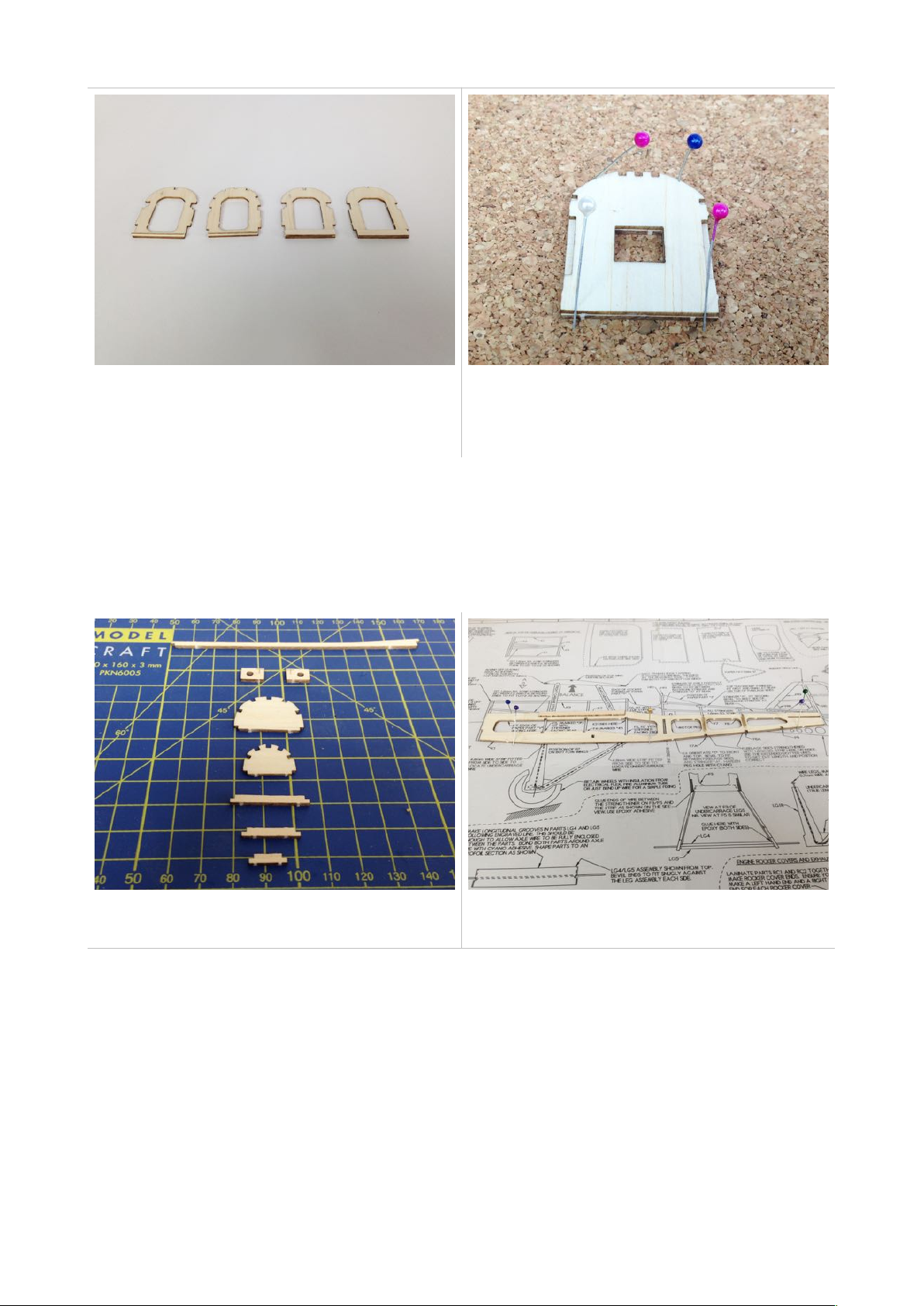
7) Pinch the rear of the fuselage and glue it together, ensuring that
the ends meet uniformly and that the fuselage remains straight and
true – use the gauge lines on the plan to help…
3) Glue the second fuselage side to the opposite end of the
formers, again making sure that all is located square and true. Leave
to set before removing from the board. !
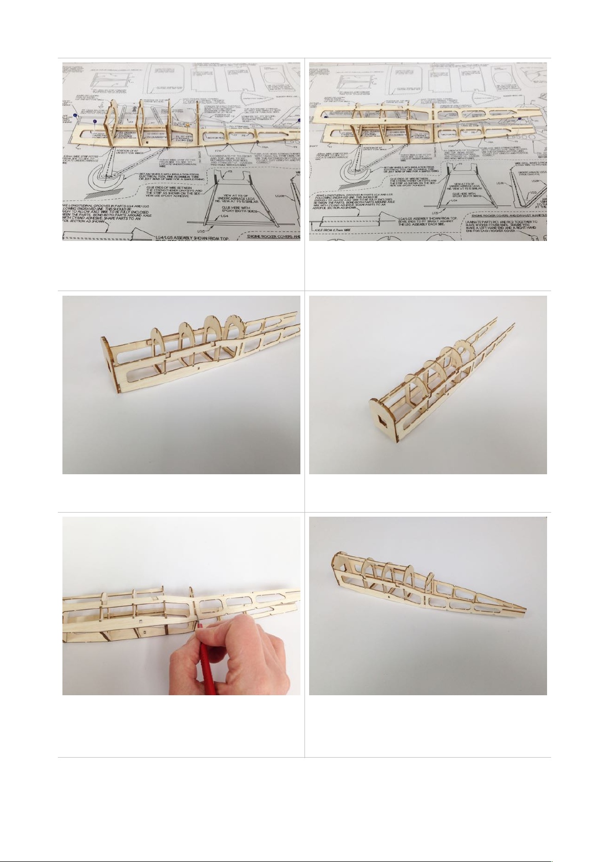
6) On the outside of each part K1, score about half the depth (not
cut through) of the part along a line immediately behind F6, noted
‘score line’ on the plan. Each side should then be ‘cracked’ inwards
forming a sharp kink in the side rather than a gentle bow.
2)… then fit and glue F3, F4, F5 and F6 in position, ensuring the
strengtheners are facing in the direction as indicated on the plan.
Make sure that all of the formers are at right angles to the fuselage
side using a square. Now leave to set.
5) Fit and glue K3 in position. The angled part should be at the rear,
nearest the cockpit.
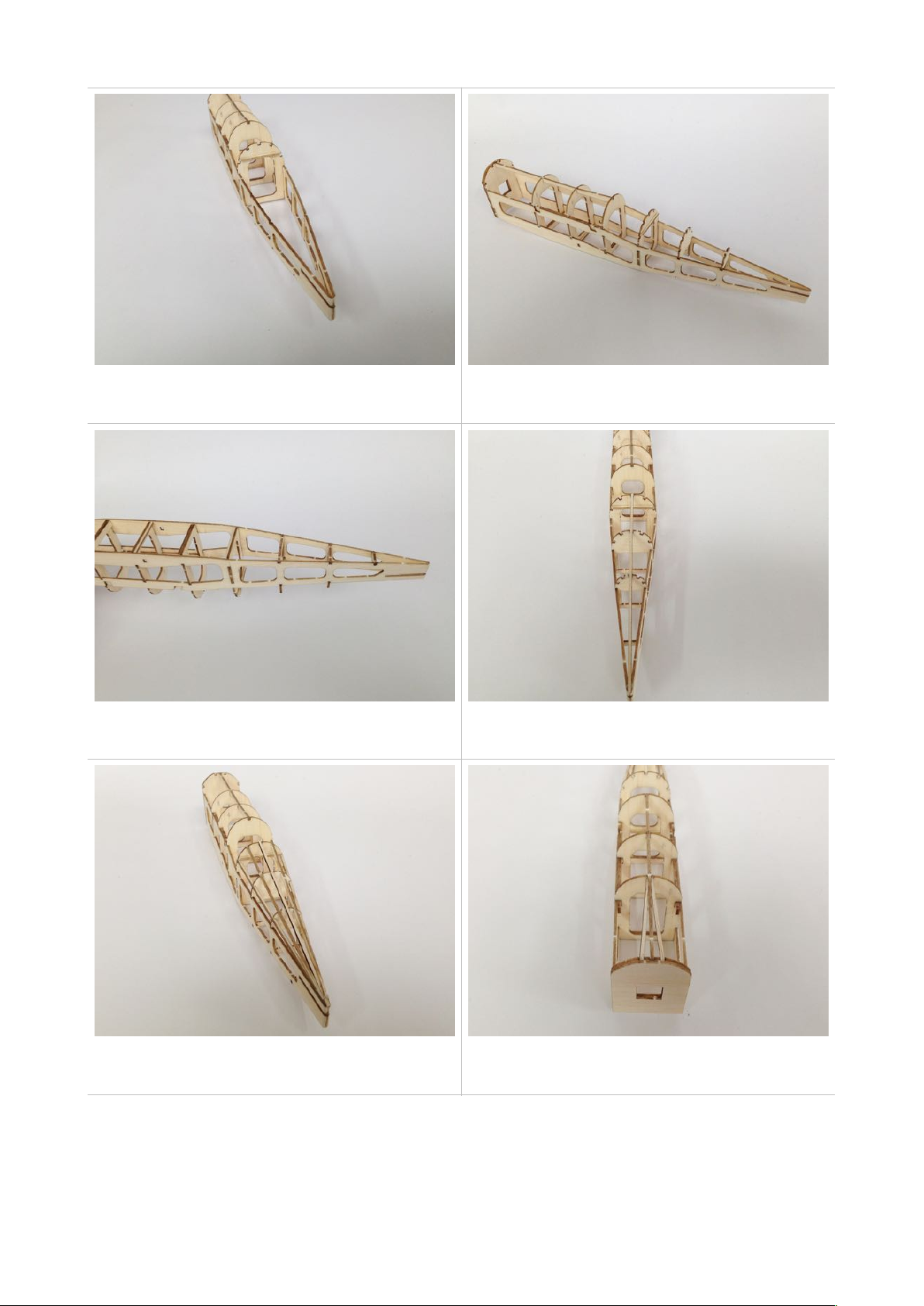
4) Bring the nose together fitting the F1 and F2 assembly. Take care
to make sure that the tabs on the fuselage locate neatly into the
slots in F2 – it should appear to be at a slight downward angle.

8) Continued
10) Fit stiff 1.6mm square strip angled stringers between F2 and F3
on the top and both sides as indicated.
8) Fit all other formers and cross pieces top and bottom working
from F7 backward, ensuring that the fuselage remains square and
true in all directions.
9) Fit and glue the remaining rear stringers, making them from light
1.6mm square strip, ensuring that the ends are bevelled to fit each
other and the fuselage sides as instructed on the plan.
7)…Hold the ends together with a clothes peg or similar until the
glue is set, then round off the end as shown on the plan.
9) Using stiff 1.6mm square strip, fit and glue the ‘backbone’
stringer in position. Note that the end sits on top of the fuselage
sides at the rear.

!
10) Continued
12) Starting with the left hand side, trial fit K4 ensuring the ‘T’ mark
is outermost and at the top, bevelling the edges to meet the
stringers top and bottom if required. Ensure a snug and flush fit to
the outer profile, then glue in position.
11) Continued… When gluing them in place, leave a gap of around
1mm (the thickness of a credit card) between them at the
strengtheners on F3 and F5. This gap will accommodate the wire
later.
11) Carefully cut two pieces of light 4.8mm strip that will go from
side to side and form the slot for the undercarriage to fit into later.
13) Repeat with part K4 on the right hand side.

ADDING THE CABANE STRUTS TO THE FUSELAGE
1) As well as the fuselage and the cabane strut jig prepared in the
previous steps, identify and remove all of the parts on the laser cut
sheets: C1 and C2 (2 off each). !
3) Continued…Once these three conditions are met, carefully pin
the jig to the R6s each side.
3) Take the top wing assembly and fit the centre section to the jig,
ensuring that: !
a) The outer faces of the centre section, rib R6, should sit flush to
the faces of the strips on the jigs. !
b) The bottom edge of the R6s should sit on the top edge of the
jig. !
c) The trailing edge of the centre section should fit snuggly to the
corner of the jig as indicated on the plan.
2) Referring to the plan, pin the cabane strut jigs to the fuselage,
one each side. The jigs should locate to F4 via the notch and the
bottom edge should lie along the fuselage side. The strips on the
jig should be good and flat to the fuselage side. Accurate
positioning of the jig is important as it sets the wing geometry.

Set the fuselage aside and complete the nose block.
6) Allow the glue to set fully. Once dry carefully un-pin the wings
from the jig and remove them. Finally remove the jigs from the
fuselage sides.
4) Trial fit each one of the cabane struts, locating them into the
‘pockets’ at the wing/centre section joint at R2/R5, bevelling them
to meet the fuselage side and the part K2. Do not force the parts to
fit – it will only cause the wing to shift in the jig and ruin the
geometry.
5) Once all four struts are a good fit, glue them in position AT THE
FUSELAGE END ONLY – DO NOT GLUE THE CABANE
STRUTS TO THE WING AT THIS STAGE. The wing will be
glued to them after both they and the fuselage are covered.
Table of contents